Adjusting the differential on a UAZ Patriot SUV
The device by which torque is divided between the wheels is called a differential. Thanks to its presence on the UAZ Patriot SUV, it is possible to change the rotation speed of each of the wheels. After all, when you turn the steering wheel, the outer wheel moves in a larger arc than the inner one and travels a greater distance. If differentials are not installed on the car, the wheels will slip when turning. This will lead to rapid tire wear, damage to the transmission, steering mechanism and accidents on the road. To eliminate this phenomenon, cars are equipped with a differential. Thanks to this element, it is possible to rotate the wheels at different angular speeds, which eliminates their actual slipping when turning. But today we will pay attention not to the design of the differential on the UAZ Patriot SUV, but to its adjustment. Why adjustment is needed and how it is carried out, let's take a closer look.
Why is adjustment needed?
Adjusting the device on a UAZ Patriot SUV is necessary for:
- improving vehicle handling and stability;
- reducing fuel consumption;
- reduction or disappearance of extraneous sounds produced by the device.
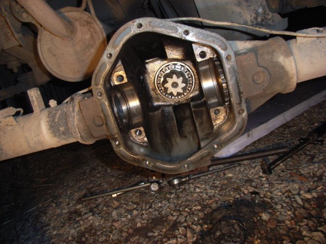
The differential has two component areas:
- rings located outside, which are pressed into the bridge;
- inner rings that are pressed onto the unit.
The device with rings is separated using special shims. Of course, adjusting the front device is not an easy process, but if you have the will, anything is possible. Thus, knowing why differential adjustment is needed, let’s proceed to the actual process.
Features of setting up the front gearbox
Let's first consider how the front differential is adjusted on a UAZ Patriot SUV. To remove the inner rings you will need to use a special puller. The differential base is equipped with two notches, so you need to take a bolt with a half-inch head or a mandrel and insert it into the hole of the axle shaft. The process of removing the rings located outside is a much more labor-intensive process. To remove it you will need to use a reverse puller. Next, use a hammer to knock out the bearing. The bearings must be reinstalled using a copper drift and hammer. Bearing adjustment is carried out by installing a set of cuffs. Thanks to the presence of these gaskets, the bearings rotate freely.
Adjusting the rear differential
Adjustment of the rear unit on the UAZ Patriot SUV is carried out in a certain sequence:
- The rings located inside are pressed on. To do this, they should be positioned so that there is a gap of 3.5-4 mm between the bearings and satellites.
- The unit is installed as a set in the crankcase and closed with a lid. Now you need to grab the product and turn it until the rollers are in the correct position. After the rollers take the required position, you can fix the cover.
- Now the brackets are unscrewed and the previously mounted cover is removed. The rear axle gearbox of the SUV is removed from the crankcase, and the gap between the bearings and the gearbox is measured.
In order to adjust the bearings of the rear axle drive gear, you need to do the following:
- Bearings are pressed onto the drive gear.
- After the support bearing is installed, it is necessary to open the end part of the shank.
- The spacer sleeve and cuffs for adjustment must be placed between the inner rings.
- A ring is placed to adjust the gear.
- The gear complete with bearings is installed in the crankcase. After installation, the bearing tension should be adjusted by changing the thickness of the spacers.
- The oil removal ring and flange are located on the shaft. The cover must be removed so that friction does not affect the data received from the devices.
- If the adjustment was carried out correctly, then the gap between the axles should be zero. In this case, the spring dynamometer should show a value of 15-30 N.
- After the adjustment process is completed, it is necessary to remove the rear axle flange and reinstall the gasket and cover. The cover is secured with bolts and nuts, and the flange must be secured with a nut and cotter pin.
Adjusting the side clearance
In order to adjust the side clearance and the location of the gears of the main transmission of the rear differential axle, it is necessary to carry out the following steps:
- The crankcase is installed in the differential. A gasket is placed between the crankcase connector and the cover. The latter must be secured with bolted connections.
- The process of taking measurements between the teeth of the drive and driven gears is carried out. This gap should be about 0.2-0.6 mm. The measurement is carried out along the drive gear flange with a radius of 40 mm.
- The side gap needs to be adjusted by shimming the differential.
- When removing shims from the driven gear, you need to know that this increases the clearance, and if they are added, the clearance correspondingly decreases. The gaskets can be rearranged, but it is forbidden to change their number on the UAZ Patriot SUV.
- If there is an adjusting ring on the rear axle, it is necessary to check the engagement of the gears.
- In this case, you will need to open the driven gear with paint.
- By braking the axle shafts, the driven gear should be stopped. The driving gear rotates until a clear spot of paint appears.
- The differential drive gear is shifted by installing an adjusting ring of a different size. The driven gear is shifted by replacing the rear axle differential bearing spacers on the UAZ Patriot SUV.
This completes the process of adjusting the rear axle differential on the UAZ Patriot SUV. After this, the rear axle of the UAZ Patriot is installed.
Build process
In order to assemble the rear unit device, you will need:
- Install a pack of gaskets, the thickness of which should exceed the gap by 1.3 times.
- Install the cover with the gasket, and then tighten it with bolts.
- A flange with a washer is installed, after which the nut is tightened until it stops. A cotter pin is installed in the hole.
- The product is located in the differential housing.
- Don't forget to install a gasket between the crankcase and the cover.
- By turning the drive gear, you can analyze whether there is any binding. After assembling the rear unit, you should check the crankcase heating temperature. If the crankcase gets very hot above 90 degrees, then the adjustment process should be repeated.
To summarize, we can say that if the differential is not adjusted, then the product will soon need to be repaired, which is quite expensive and unpredictable.
Source: prohodimets.ru
Adjusting the bearings of the main drive of the front axle UAZ 31519
Adjust the final drive bearings in the following order.
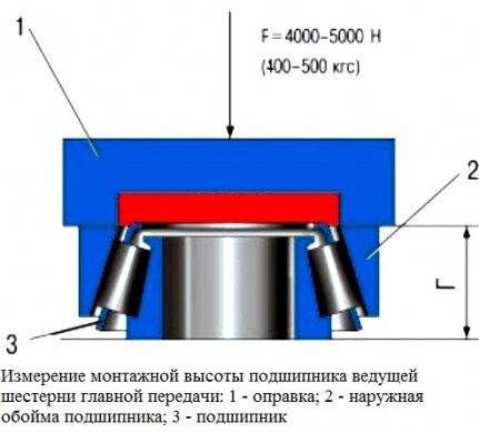
Rice. 6.7. Measuring the mounting height of the main gear drive gear bearing: 1 – mandrel; 2 – outer race of the bearing; 3 – bearing
Install the ring into the crankcase 16 (see.
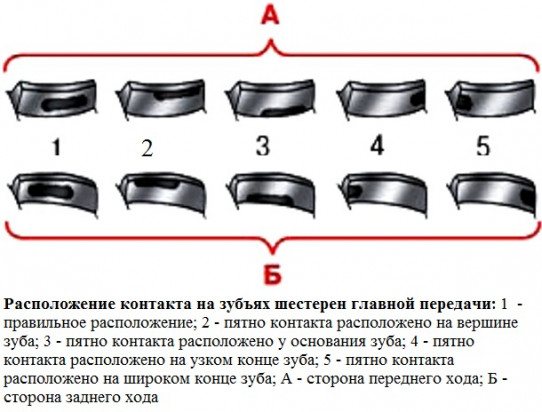
Rice. 6.9 . Location of the contact on the teeth of the main gear gears: 1 – correct location; 2 – the contact patch is located at the top of the tooth; 3 – the contact patch is located at the base of the tooth; 4 – the contact patch is located at the narrow end of the tooth; 5 – the contact patch is located at the wide end of the tooth; A – forward side; B – reverse side
7. Check the engagement of the main gear gears along the contact patch. To do this, apply paint to the teeth of the driven gear (2 teeth in three or four places evenly around the circumference).
8. Braking the drive gear shaft by the flange, rotate the driven gear in both directions until contact marks appear on the gear teeth, as shown in Fig. 6.9.
When adjusting the gear mesh correctly, the contact patch should be located in the tooth locations shown in
rice.
6.9 (item 1).
When contacting along the top of the tooth (item 2), move the drive gear towards the driven gear, increasing the thickness of the adjusting ring, while moving the driven gear away from the drive gear to maintain the side clearance value.
If there is contact at the base of the tooth (item 3), move the drive gear away from the driven gear by reducing the thickness of the adjusting ring, and to maintain the side clearance value, move the driven gear towards the drive gear.
If there is contact at the narrow end of the tooth (item 4), move the driven gear away from the drive gear by reducing the thickness of the adjusting ring, while moving the drive gear towards the driven gear to maintain the side clearance value.
If there is contact at the wide end of the tooth (item 5), move the driven gear towards the drive gear by increasing the thickness of the adjusting ring, and to maintain the side clearance value, move the drive gear away from the driven gear.
9. Install the locking plate on the differential bearing cap.
The locking plate can be installed in the teeth of the adjusting nut with one or two "tendrils". If it is not possible to install the locking plate in a certain position, tighten the adjusting nut until the teeth and the locking plate are closest to each other.
10. Having assembled the main gear, check its heating after a test drive of the car. If the front axle crankcase in the area of the drive gear bearings and differential bearings heats up above 90 ° C (the water on the crankcase is boiling), then adjust the bearing preload again as indicated above.
Video about “Adjusting the front axle final drive bearings” for UAZ 31519
Adjusting the UAZ shank UAZ/GAZ/GAZELLE - Axle repair - Part 3 - Adjustment and assembly UAZ Patriot axle reducer
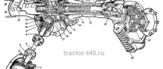
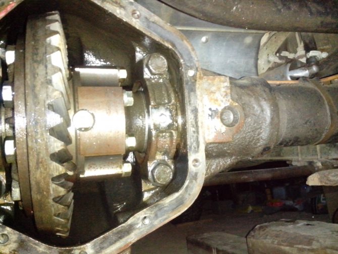
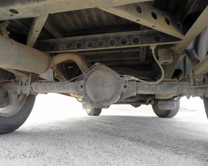
Rear axle structure and diagram
The rear axle “Spicer” on the UAZ Patriot is a cast crankcase with pressed-in axle shafts, on which platforms are provided for springs. Inside the housing there is a bevel main pair and a differential, the gears are mounted on tapered roller bearings and bronze bushings. Lubrication is carried out by splashing, the oil is stored in the lower part of the crankcase. There is a plug on the side of the housing for checking the level and filling in fresh fluid.
The design of the front axle of the UAZ Patriot differs from the design of the rear beam. The front wheels are mounted on steering knuckles, which are equipped with constant velocity joints. To transmit power to the main pairs, cardan shafts are used, connected to a 2-speed transfer gearbox.
Front axle structure of UAZ Patriot
The front axle of the UAZ Patriot car consists of:
- Gearbox;
- Housings;
- Two axle shafts;
- Axle shaft housings;
- Steering knuckles;
- Brackets for mounting springs and shock absorbers.
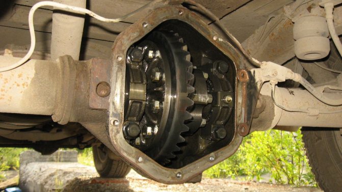
Gearbox
The front axle gearbox of a car consists of a main gear and a cross-axle differential. The main gear is made in the form of two gears. The drive gear is small and mounted on the drive shaft. The driven gear is increased in size, which reduces the torque transmitted to the wheel mechanisms. The gear teeth are angled. When the unit operates, the gear teeth do not hit each other. This reduces the noise level while the vehicle is moving.
An inter-axle differential is installed inside the driven gear of the front axle gearbox. When turning a car, it allows the wheels of the same axle to rotate at different speeds. The cross-wheel differential is made in the form of bevel gears mounted on two axles. The splined part of the axle shafts is included in the cross-axle differential mechanism.
Steering knuckles
A distinctive feature of the front axle is the presence of steering knuckles. They are necessary to drive a car. To transmit torque to the wheel mechanisms, regardless of their angle of rotation, the manufacturer equipped the axle shafts with CV joints.
REFERENCE: Unlike previous models of the Ulyanovsk Automobile Plant, the UAZ Patriot has a greater angle of rotation of the wheel mechanisms. This is achieved by installing ball joints instead of a pin mechanism.
Frame
The design of the front axle of the UAZ Patriot implies the presence of an all-metal housing that forms the gearbox housing. To ensure tightness, the gearbox housing is closed with a lid. It is installed with bolts. A gasket is installed at the junction of the cover and the gearbox housing. On the side of the wheel mechanisms, axle shaft housings are pressed into the gearbox housing.
ATTENTION: To avoid the occurrence of excess pressure in the front axle crankcase as a result of increased temperature, lubrication, the manufacturer has installed a breather valve. It communicates the axle housing with the atmosphere, preventing dust and contaminants from entering the mechanism.
Main pair adjustment
After repairing the front axle associated with replacing gears, it is necessary to adjust the contact patch:
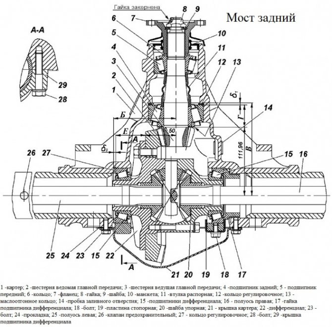
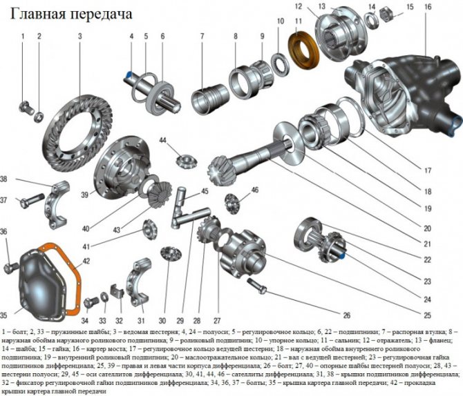
- Select a spacer ring (parts are produced with a tolerance of 0.025 mm in both directions) that provides the required clearance in the tapered bearings of the drive shaft. When selecting, the distance between the center of the axle shaft and the lower edge of the spacer sleeve (parameter A) is taken into account. It is also necessary to take into account the gap between the edge of the inner ring and the opposite edge of the outer ring (parameter B). The thickness of the ring is determined by the formula C=A-(111.96+B).
- Place the ring in the seat.
- Insert the outer bearing races of the drive shaft into the crankcase.
- Place the oil drain ring onto the drive shaft, and then mount the rear bearing.
- Install the spacer sleeve and insert the shank into the crankcase.
- Place the 2nd bearing on the drive shaft, the ring is mounted until it stops.
- Install the washer on the spline part, and then put on the flange (used to connect the driveshaft).
- Secure the ring and flange with a nut, tighten the threaded connection until the axial play is eliminated. The shaft rotation force should not be higher than 2.0 N*m if new bearing supports are used. If old bearings are used, the torque value is 0.4-0.8 N*m. The tightening torque of the nut should be in the range from 180 to 250 N*m; when increased force is applied, the spacer sleeve is compressed.
- Apply marks to the surface of the flange and nut (for example, with oil paint or nitro enamel), which are used for further adjustment of the bridge.
- To mount the differential in the crankcase cavity, you need to purchase several sets of adjusting washers that differ in thickness.
- Install the original washer (which was used with the old gears), and then open the structure with the nut, which is located on the right side.
- Apply oil paint or other coloring material that does not dry for 30-40 minutes to the gear teeth.
Turn the gears 3-4 turns and inspect the imprint that appears on the drive gear. If the spot has an oval configuration and is located in the central part of the teeth, then the adjustment is correct. The shift of the spot towards the top of the tooth indicates the need for the shank to move closer to the differential gear, but at the same time the driven wheel is moved away from the drive gear.
If the spot is shifted to the base, then the drive wheel is moved away from the driven wheel (by reducing the thickness of the adjusting ring). To keep the side clearance within acceptable limits, it is necessary to move the driven gear towards the drive gear. When the spot moves to the narrow or wide end of the tooth, it is necessary to move or move the driven gear accordingly.
After the adjustment is completed, an oil seal is installed to prevent oil leakage. Then the shank bearings are tightened (until the paint marks align). To prevent spontaneous unscrewing of the threaded connection, the nut flange is jammed into a special groove provided on the side surface of the shaft.
Adjusting the bearings of the final drive of the UAZ Patriot
Axial play in the bearings of the main gear drive gear is not allowed, since if it is present, rapid wear of the gear teeth occurs and the axle may jam.
Check for the presence of axial clearance by rocking the drive gear by the driveshaft mounting flange.
To eliminate the axial play of the drive gear, it is necessary to tighten nut 8 (Figure 1).
At the same time, keep in mind that the nut is cored into the groove of the threaded part of the drive gear and when tightening it will require more force on the wrench.
Tighten the nut carefully until the axial play of the drive gear is eliminated, avoiding overtightening, then tighten the nut.
If it is not possible to tighten the cored nut, then it should first be loosened by 0.5 - 1.0 turns, and then tightened until the axial gap is eliminated and cored.
Axial play in the final drive differential bearings is also not allowed.
Check it by rocking driven gear 2 with crankcase cover 21 removed.
Eliminate the axial play of the driven gear of the main gear by tightening the nut 17 of the differential bearing, having first removed the locking plate 19.
Adjust the main drive bearings in the following order.
1. Select adjusting ring 5 (see Fig. 1). Its thickness d1 (Fig. 2) is determined (with an accuracy of ±0.025 mm) based on the actual dimensions B and D (see Fig. 2 and 3) using the formula d1 = B – (111.960 + G) (mm).
Install the ring into housing 16 (see Fig. 1) of the main gear.
2. Install the drive gear shaft into the front axle housing.
Check the torque of the drive gear shaft. It should be 1.0–2.0 N cm (0.1–0.2 kgf cm).
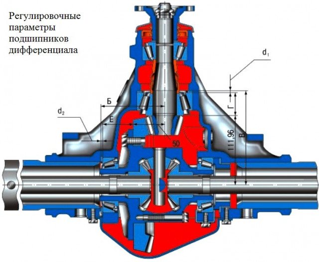
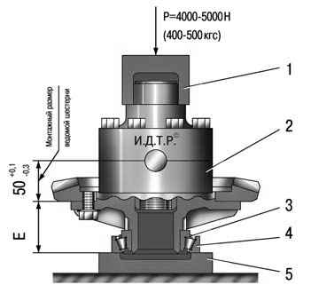
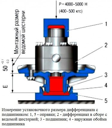
3. When installing the differential assembly with the driven gear, measure dimension E (Fig. 4), applying an axial force P equal to 4000–5000 N (400–500 kgf), and turning the gear several times so that the bearing rollers take the correct position.
Measure distance B in the crankcase (see Fig. 2) from the axis of the drive gear to the thrust end of the differential bearing.
Based on the actual dimensions B, E and the mounting size of the driven gear, equal to 50 mm, select (with an accuracy of ±0.025 mm) the adjusting ring according to the formula d2 = B – (E + 50 + X) (mm), where d2 is the thickness of the adjusting ring; X - maximum deviation from the mounting dimension, equal to 50 mm, with the corresponding sign (plus or minus), this dimension is applied with an electrograph to the end of the driven gear.
4. Install the differential assembly with the outer rings of its bearings and the adjusting ring into the front axle housing and secure it.
5. Adjust bearings 6 and 22 (see Fig. 1) of the front axle differential by tightening nut 23, periodically rotating the differential so that the bearing rollers take the correct position. After tightening the nut, the total turning torque of the differential drive gear (Mv.w.) must be within Mw. w. + (0.21–0.42) (Nm) . Perform the check by turning the drive gear.
Check and adjust the lateral clearance in the meshing of the gears of the installed new final drive kit after adjusting the position of the gears.
The lateral clearance is checked with an indicator, the stand of which is attached to the axle housing in the direction perpendicular to the surface of the driven gear tooth when the indicator stand is attached to the housing.
Check the gap on three or four teeth evenly spaced around the circumference.
The spread of the gap values should not exceed 0.05 mm.
Normal side clearance should be between 0.15–0.25 mm.
If the side clearance is less than the specified value, then the selected adjusting ring should be replaced with a ring of thinner thickness.
When checking and adjusting the side clearance, it is not necessary to preload the differential bearings.
6. Tighten the adjusting nut 23 until it comes into contact with the bearings and there is no gap in them.
7. Check the engagement of the main gears along the contact patch by painting the teeth of the driven gear with paint (2 teeth in three or four places evenly around the circumference).
8. Braking the drive gear shaft by the flange, rotate the driven gear in both directions until contact marks appear on the gear teeth, as shown in Fig. 5
When adjusting the gear mesh correctly, the contact patch should be located in the places of the teeth shown in the figure (item 1)
When there is contact at the top of the tooth (item 2), move the drive gear towards the driven gear, increasing the thickness of the adjusting ring, and to maintain the value of the side clearance, move the driven gear away from the drive gear.
If there is contact at the base of the tooth (item 3), move the drive gear away from the driven gear by reducing the thickness of the adjusting ring, and to maintain the side clearance value, move the driven gear towards the drive gear.
If there is contact at the narrow end of the tooth (item 4), move the driven gear away from the drive gear by reducing the thickness of the adjusting ring, while moving the drive gear towards the driven gear to maintain the side clearance value.
If there is contact at the wide end of the tooth (item 5), move the driven gear towards the drive gear by increasing the thickness of the adjusting ring, and to maintain the side clearance value, move the drive gear away from the driven gear.
Install the locking plate onto the differential bearing cap.
After assembling the final drive, check its heating after a test drive of the car.
If the front axle housing in the area of the pinion bearings and differential bearings heats up above 90°C, then adjust the bearing preload again as indicated above.
How to check the correctness of the work done
A basic check of the bridge's performance is carried out by measuring the crankcase temperature. The car must be driven on a dry road for 25-30 km; an electronic thermometer is used to check the degree of heating. The plant allows the crankcase temperature to increase near the installation sites of the liner bearing supports to 90°C. Water can be used to roughly estimate the degree of heating: the liquid applied to the bridge body should not boil. At elevated temperatures, the axial clearance in the bearing supports is re-adjusted.
During operation, increased noise, which occurs due to the gap between the gears and the displacement of the contact patch, is not allowed. During the grinding process of parts, the extraneous sound does not disappear, but only increases due to accelerated wear of gears and bearings. A knocking noise in the axle that occurs during sudden acceleration or release of gas indicates an excessive gap between the teeth. If extraneous sounds are detected, you need to return to the repair area and check the adjustment of the gaps in the main pair.
Source: myuazpatriot.ru
Adjusting the differential on a UAZ Patriot SUV
The device by which torque is divided between the wheels is called a differential. Thanks to its presence on the UAZ Patriot SUV, it is possible to change the rotation speed of each of the wheels. After all, when you turn the steering wheel, the outer wheel moves in a larger arc than the inner one and travels a greater distance. If differentials are not installed on the car, the wheels will slip when turning. This will lead to rapid tire wear, damage to the transmission, steering mechanism and accidents on the road. To eliminate this phenomenon, cars are equipped with a differential. Thanks to this element, it is possible to rotate the wheels at different angular speeds, which eliminates their actual slipping when turning. But today we will pay attention not to the design of the differential on the UAZ Patriot SUV, but to its adjustment. Why adjustment is needed and how it is carried out, let's take a closer look.
Why is adjustment needed?
Adjusting the device on a UAZ Patriot SUV is necessary for:
- improving vehicle handling and stability;
- reducing fuel consumption;
- reduction or disappearance of extraneous sounds produced by the device.
The differential has two component areas:
- rings located outside, which are pressed into the bridge;
- inner rings that are pressed onto the unit.
The device with rings is separated using special shims. Of course, adjusting the front device is not an easy process, but if you have the will, anything is possible. Thus, knowing why differential adjustment is needed, let’s proceed to the actual process.
Features of setting up the front gearbox
Let's first consider how the front differential is adjusted on a UAZ Patriot SUV. To remove the inner rings you will need to use a special puller. The differential base is equipped with two notches, so you need to take a bolt with a half-inch head or a mandrel and insert it into the hole of the axle shaft. The process of removing the rings located outside is a much more labor-intensive process. To remove it you will need to use a reverse puller. Next, use a hammer to knock out the bearing. The bearings must be reinstalled using a copper drift and hammer. Bearing adjustment is carried out by installing a set of cuffs. Thanks to the presence of these gaskets, the bearings rotate freely.
Adjusting the rear differential
Adjustment of the rear unit on the UAZ Patriot SUV is carried out in a certain sequence:
- The rings located inside are pressed on. To do this, they should be positioned so that there is a gap of 3.5-4 mm between the bearings and satellites.
- The unit is installed as a set in the crankcase and closed with a lid. Now you need to grab the product and turn it until the rollers are in the correct position. After the rollers take the required position, you can fix the cover.
- Now the brackets are unscrewed and the previously mounted cover is removed. The rear axle gearbox of the SUV is removed from the crankcase, and the gap between the bearings and the gearbox is measured.
In order to adjust the bearings of the rear axle drive gear, you need to do the following:
- Bearings are pressed onto the drive gear.
- After the support bearing is installed, it is necessary to open the end part of the shank.
- The spacer sleeve and cuffs for adjustment must be placed between the inner rings.
- A ring is placed to adjust the gear.
- The gear complete with bearings is installed in the crankcase. After installation, the bearing tension should be adjusted by changing the thickness of the spacers.
- The oil removal ring and flange are located on the shaft. The cover must be removed so that friction does not affect the data received from the devices.
- If the adjustment was carried out correctly, then the gap between the axles should be zero. In this case, the spring dynamometer should show a value of 15-30 N.
- After the adjustment process is completed, it is necessary to remove the rear axle flange and reinstall the gasket and cover. The cover is secured with bolts and nuts, and the flange must be secured with a nut and cotter pin.
Adjusting the side clearance
In order to adjust the side clearance and the location of the gears of the main transmission of the rear differential axle, it is necessary to carry out the following steps:
- The crankcase is installed in the differential. A gasket is placed between the crankcase connector and the cover. The latter must be secured with bolted connections.
- The process of taking measurements between the teeth of the drive and driven gears is carried out. This gap should be about 0.2-0.6 mm. The measurement is carried out along the drive gear flange with a radius of 40 mm.
- The side gap needs to be adjusted by shimming the differential.
- When removing shims from the driven gear, you need to know that this increases the clearance, and if they are added, the clearance correspondingly decreases. The gaskets can be rearranged, but it is forbidden to change their number on the UAZ Patriot SUV.
- If there is an adjusting ring on the rear axle, it is necessary to check the engagement of the gears.
- In this case, you will need to open the driven gear with paint.
- By braking the axle shafts, the driven gear should be stopped. The driving gear rotates until a clear spot of paint appears.
- The differential drive gear is shifted by installing an adjusting ring of a different size. The driven gear is shifted by replacing the rear axle differential bearing spacers on the UAZ Patriot SUV.
This completes the process of adjusting the rear axle differential on the UAZ Patriot SUV. After this, the rear axle of the UAZ Patriot is installed.
Build process
In order to assemble the rear unit device, you will need:
- Install a pack of gaskets, the thickness of which should exceed the gap by 1.3 times.
- Install the cover with the gasket, and then tighten it with bolts.
- A flange with a washer is installed, after which the nut is tightened until it stops. A cotter pin is installed in the hole.
- The product is located in the differential housing.
- Don't forget to install a gasket between the crankcase and the cover.
- By turning the drive gear, you can analyze whether there is any binding. After assembling the rear unit, you should check the crankcase heating temperature. If the crankcase gets very hot above 90 degrees, then the adjustment process should be repeated.
To summarize, we can say that if the differential is not adjusted, then the product will soon need to be repaired, which is quite expensive and unpredictable.
Source: prohodimets.ru
Spicer UAZ front axle design
The front axle of the UAZ Patriot Spicer is structurally different from the rear axle. This is due to the fact that the front axle is used to steer the car. The Spicer front axle consists of:
- Carter;
- Gearbox;
- Half shafts;
- Rotary steering mechanisms.
Carter
The axle housing is one-piece. On the side of the wheel mechanisms, axle shaft casings are pressed into it. The gearbox is accessible after removing the cover. It is necessary to ensure the tightness of the crankcase and is bolted to the housing. A gasket is installed between the cover and the crankcase.
In the front part of the crankcase there is a hole for the shaft that transmits torque from the cardan to the main gear. To seal the crankcase, an oil seal is installed in the hole. Brackets for mounting springs and shock absorbers are installed on the axle housing housing. To reduce pressure in the crankcase when the lubricant heats up, a wheelbarrow breathing valve is provided
Gearbox
The Spicer front axle device includes a gearbox. It consists of a main gear and a cross-axle differential. The main gear is made in the form of two gears. The drive gear is bevel type, small in size. Rigidly connected to the front axle drive shaft. Large diameter driven gear.
REFERENCE: The teeth of the main gear gears are located at an angle. When engaged, the gear teeth do not hit each other. This reduces the noise level during operation of the unit.
An interwheel differential is located inside the driven gear. It is made in the form of four bevel gears mounted on two axes. This design allows wheels of the same axle to rotate at different speeds. This is necessary when turning or turning the car.
Adjusting the bearings of the main drive of the front axle UAZ Patriot 3163
Adjust the main drive bearings in the following order.
Rice. 6.8 . Location of the contact patch on the teeth of the main gear gears: A – forward side; B – reverse side; 1 – correct location; 2 – the contact patch is located at the top of the tooth; 3 – the contact patch is located at the base of the tooth; 4 – the contact patch is located at the narrow end of the tooth; 5 – the contact patch is located at the wide end of the tooth
6. Tighten the adjusting nut 23 until it comes into contact with the bearings and there is no gap in them.
7. Check the engagement of the main gears along the contact patch by painting the teeth of the driven gear with paint (2 teeth in three or four places evenly around the circumference).
8. Braking the drive gear shaft by the flange, rotate the driven gear in both directions until contact marks appear on the gear teeth, as shown in Fig. 6.8.
When adjusting the gear mesh correctly, the contact patch should be located in the tooth locations shown in
rice.
6.8 (item 1).
When there is contact at the top of the tooth (item 2), move the drive gear towards the driven gear, increasing the thickness of the adjusting ring, and to maintain the value of the side clearance, move the driven gear away from the drive gear.
If there is contact at the base of the tooth (item 3), move the drive gear away from the driven gear by reducing the thickness of the adjusting ring, and to maintain the side clearance value, move the driven gear towards the drive gear.
If there is contact at the narrow end of the tooth (item 4), move the driven gear away from the drive gear by reducing the thickness of the adjusting ring, while moving the drive gear towards the driven gear to maintain the side clearance value.
If there is contact at the wide end of the tooth (item 5), move the driven gear towards the drive gear by increasing the thickness of the adjusting ring, and to maintain the side clearance value, move the drive gear away from the driven gear.
9. Install the locking plate onto the differential bearing cap.
10. Having assembled the final drive, check its heating after a test drive of the car. If the front axle housing in the area of the pinion bearings and differential bearings heats up above 90 ° C, then adjust the bearing preload again as indicated above.
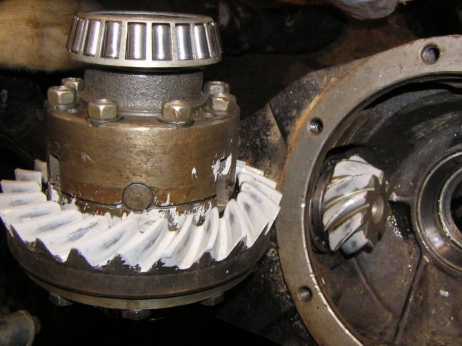
Rear axle UAZ Patriot Spicer gearbox adjustment
A lot of people in private messages asked me to publish in more detail how I installed new main couples in Spicer. In no way do I claim to be an exemplary solution, just my personal experience. In total, 4 g.p. were changed in this way. Yesterday I did a hunter, installed lower pairs (there are also spicer bridges). The front and rear axles are the same, with the exception of small nuances - you have to remove the hubs at the front, and you don’t even need to jack the rear ones, just pull out the axle shafts and that’s it, disassembly and assembly of the axle can be seen here: www.drive2.ru/l/9015967/, www.drive2. ru/l/9093386/, www.drive2.ru/l/9093672/, www.drive2.ru/l/9104055/ and bridge assembly: www.drive2.ru/l/9885152/, www.drive2.ru/l /9885438/ And so the adjustment of the front/rear main pair: Let’s imagine that you have completely pulled out all the guts from the axle gearbox. 1. Place the adjusting washer and press in the race of the internal bearing of the shank; 2. Press in the outer shank holder (the one on the cardan side); 3. Put the oil squeegee on the shank, press the bearing in (by the way, it’s very convenient to do this with an old race) 4. Put on the spacer sleeve, and put the shank in the seat; 5. From the cardan side, we put the bearing on the shank and press it in until it stops 6. We put the washer on the splines (the washer is like this with teeth on the inside); 7. We put on the flange (we don’t install the oil seal yet), the washer and tighten the nut, twist until there is no play at all. We put paint stripes on the nut and on the flange so as not to overtighten the bearings later. 8. We install the diff assembly (at the same time we stock up on adjusting rings in the store, I bought 4 thinner than it was, and 4 thicker than it was, then I handed it all back to the store, they are not damaged); 9 We put the original washer, spread it with the nut, which is on the right side, apply paint that does not dry out for a long time (I used an ordinary stationery corrector, water-based) 10. Scroll the main pair a couple of times and look at the pattern of the shank teeth on the driven gear
If the pattern is different, choose which one is similar to yours, and proceed to adjustment:
Let me explain the adjustment: 1. correct contact in engagement 2. It is necessary to move the shank by increasing the thickness of the adjusting ring, while in order to maintain the amount of side clearance, move the driven gear away from the drive gear by reducing the thickness of the ring 3. It is necessary to move the shank by reducing the thickness of the adjusting ring, while to maintain the value of the side clearance, move the driven gear towards the drive gear by increasing the thickness of the ring 4. It is necessary to move the shank by increasing the thickness of the adjusting ring, while in order to maintain the value of the side clearance, move the driven gear away from the drive gear by reducing the thickness of the ring 5. It is necessary to move the shank away by reducing the thickness of the adjusting ring , at the same time, to maintain the value of the side clearance, move the driven gear towards the drive gear by increasing the thickness of the ring. I had enough adjustment with the ring on the left “diff”; in 4 cases the original washer remained under the race of the inner shank bearing. AND THE MOST IMPORTANT THING! After adjustment, do not forget to press in the bridge seal and tighten the flange and lock the nut. Tighten the nut until the marks previously applied to the nut and flange match.