MTZ tractor engines are equipped with a removable head, which is installed on the cylinder block and secured with bolts. The reliability of the power unit depends on the correct installation of parts and compliance with the tightening torque of the MTZ cylinder head. When exhaust gases or coolant break through, power is reduced and components of the piston group and gas distribution mechanism of the engine are destroyed.
The importance of correct cylinder head torque
The cylinder head is held on the crankcase with bolts that evenly distribute the compression force of the parts, preventing the destruction of the gasket by hot gases. To ensure uniform contact, the bolt is tightened with a torque wrench; the threaded connections are tightened according to the pattern laid down by the developer of the power unit. The gasket installed between the head and the block is deformed when tightened, ensuring the tightness of the joint line.
If the tightening torque is exceeded, deformation of the bolt and thread cut in the body of the block occurs. Due to the stretching of the rod of the connecting part, the uniformity of the mating planes of the head and the block is disrupted, which leads to breakdown of the gasket by the gas flow. A similar problem occurs if the cylinder head to block bolts are not tightened enough.
Adjustment procedure
By adjustment we mean ensuring a regulated gap between the plane of the rocker arm striker and the end of the air intake and exhaust gas exhaust valves into the exhaust manifold. The setting sequence and parameters depend on the modification of the power unit and the method of supplying air to the combustion chamber. Additionally, the tightness of the nuts securing the head to the cylinder block is checked, which reduces the likelihood of gasket breakdown and warping of the part due to uneven thermal deformations.
Preparing the tightening surface of the block and head
The head is installed in its original place after partial or major repair of the engine units and components. Before installing the head, new liners are installed in the block, which are sealed with special rubber rings that prevent coolant from leaking out of the jacket. The installed sleeve protrudes with its upper edge above the plane of the block. Pistons and liners are selected according to one size group, and the connecting rods and pistons are additionally weighed. The permissible difference in weight should not exceed 30 g.
To connect the connecting rod and piston, the pin is pressed into the piston using a special mandrel, and then secured against longitudinal movement with locking rings. A correctly selected finger does not move in the mounting sockets under the influence of its own weight.
The skew of the pin in the hole of the connecting rod bearing, as well as bending or conical wear of the cylindrical element is not allowed.
Rings are installed in the grooves on the piston body to provide compression and remove traces of oil from the surface of the liner. MTZ naturally aspirated engines use 3 compression rings, supercharged engines are equipped with 2 rings, the top one is coated with a wear-resistant chromium-based alloy. The ring locks are placed at 180° intervals, providing increased compression. When installing parts, you need to pay attention to the marks indicating the correct location of the rings relative to the piston bottom.
Before installing the pistons, it is necessary to install the crankshaft in its original place (if it was dismantled for grinding from the replacement). Then a piston with a connecting rod is installed in the cylinder liner, after which the liners are mounted and the caps of the main and connecting rod bearings are tightened. To check the correct assembly, use a torque wrench to turn the engine shaft.
The standard force should not exceed 60 N/m; if there is increased resistance to rotation, it is necessary to find the cause of the malfunction.
Installing the gasket and cylinder head on the block
The gasket is placed on the upper surface of the block, previously wiped with a clean rag. It is first recommended to check the condition of the aligned planes of the block and head with a metal tool ruler. Warping of parts is not allowed, since curved surfaces do not provide uniform clamping of the gasket, which will be pierced by the flow of exhaust gases. Damaged planes are ground on a special machine, and a metallized gasket with an increased thickness of material is used to seal the joint.
MTZ tractor timing belt
_____________________________________________________________________________
_____________________________________________________________________________
____________________________________________________________________________________________
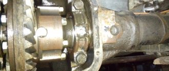
The main parameters of the distribution mechanism of engines D-245, 243, 240 are given below. The working surfaces of the camshaft bearing journals and cams must be clean, without nicks or marks. The height of the camshaft cams should be 41.32±0.05 mm for naturally aspirated diesel engines and 41.52±0.05 mm for turbocharged engines. The surfaces of the cams must be tapered. The larger base of the cone should be on the camshaft gear side. Parameters of timing parts D-240, 245, 243 Designation / Material / Weight, kg / Hardness of working surfaces Camshaft 245-1006015-B / Steel 45 / 4.622 / 55…63 HRCe Rod 240-1007310-B / Steel 45 / 0.194 / 45…57 НRCе Valve pusher 240-1007375-А1 (or А) / Steel 20Х / 0.123 / 56…63 НRCе Splined fuel pump drive gear flange 245-1006327 / Steel 45 / 0.244 / 40…48 НRCе Fuel pump drive gear 245- 1006311 / Steel 25ХГТ / 1.23 / 57…64 НRCе Bolt 240-1006325 / Steel 45 / 0.050 / 55…63 НRCе Camshaft gear 240-1006214-А / Steel 25ХГТ / 0.722 / 57…64 НRCе Intermediate gear 240-1006240 -A / Steel 25ХГТ / 1.752 / 57…64 НRCе Idle gear bushing 50-1006246-B / Br.05Ц5С5 / 0.130 / not less than 60 НВ Special screw 50-1006247 / Steel 40Х / 0.018 / 32…40 НRCе Idler pin 5 0 -1006253-B / Steel 45 / 0.570 / 55…65 HRCe The diameters of the camshaft journals of MTZ tractor engines must be at least 49.88 mm (for a new shaft - 50-0.050-0.089 mm). The non-roundness and tolerance of the longitudinal section profile of each camshaft journal is 0.01 mm. The oil channels of the camshaft D-245, 243, 240 must be clean, without traces of resinous deposits. The channels must be thoroughly washed and blown out with compressed air. The gear must be pressed onto the camshaft until it stops. The bolt securing the gear to the camshaft must be tightened to a torque of 110…160 Nm. The gap between the end of the journal of the assembled camshaft and the thrust flange (axial play of the shaft) is allowed within 0.3...1.04 mm. The bushing must be pressed into the idler gear flush with the ends. The surfaces of the gear and bushing ends must be clean and free of dents. The roughness of the treated surfaces is Ra 2.5 microns. The inner surface of the intermediate gear bushing must be clean, without marks or burrs. The roughness of the treated surface is Ra 2.5 microns. The out-of-roundness and tolerance of the longitudinal section profile of the inner surface of the intermediate gear bushing is 0.008 mm. The splined flange of the fuel pump drive gear must fit freely into the splines of the pump shaft sleeve without jamming. The replacement fuel pump drive gear bushing should be pressed in from the short hub side until the bushing stops at the end of the gear hub. When adjusting the gap between the end of the adjusting bolt and the surface of the bar, the adjusting bolt should be screwed all the way into the bar, then unscrewed 1/3...1/2 turn and secured with a nut. For the gas distribution mechanism D-243, 245, 240, only knocks in the valves are checked. Knocks in the timing valves are heard at any crankshaft speed (especially at low speed) under the cylinder head cover. A strong knocking sound in a warm engine indicates increased gaps between the valve stem and the rocker arm. The sound of a broken valve spring can be heard at any crankshaft speed and does not change in sound. The noise of the timing gears is heard at low crankshaft speeds in the area of the gear covers. High noise levels indicate gear wear. Determination of the total gap in the upper and lower heads of the connecting rod using a compressor-vacuum installation of the KI 13907 type. The KI 13907 installation, created by GOSNITI, is used to measure gaps in the crank mechanism using the KI-11140 and KI-13933M devices. Installing KI 13907 with the KI-11140 device allows you to measure the total clearance in the upper and lower connecting rod heads when the engine is not running without removing the oil pan. The principle of measuring gaps in the indicated interfaces is based on measuring the movement of the piston with an indicator device when alternately creating pressure and vacuum in the space above the piston. As the piston moves upward (toward TDC), the piston pin is pressed against the bottom of the connecting rod's upper head, and the crank (crankpin) is pressed against the top of the connecting rod's lower head. When the piston moves downward, the points of contact of these parts change to the opposite ones, i.e. in both cases the indicator will measure the total gap. The upward movement of the piston in the cylinder occurs under vacuum in the space above the piston, and downward movement occurs under air pressure supplied through the nozzle hole from the compressor-vacuum unit. The compressor-vacuum installation consists of an electric motor and two cylinders, in one of which a vacuum is created, and in the other - pressure. An oil and moisture separator with a safety valve is located on the cylinder, a pressure regulator with a pressure gauge, a control valve with a vacuum gauge and an air filter, a pressure reducing valve and an electric starter are located on the vacuum cylinder. On the body of the vacuum cylinder there may be a valve with a fitting for connecting the KI-4887-I device. The cylinders are connected to the cylinders of the tested diesel engine D-245, 243, 240 with a flexible hose through a control valve. The compressor is driven by an electric motor and creates pressure or vacuum. Using the KI-11140 device, the total gap in the crank mechanism is measured. It has a housing with a dial indicator attached to it, a pneumatic receiver, a replaceable flange for attaching the device to the cylinder head instead of an injector, a seal, a guide, a rod rigidly connected to the indicator leg, and a locking screw designed to fix the guide in the pneumatic receiver. To diagnose connecting rod connections in a MTZ diesel engine using the KI-13907 installation and the KI-11140 device, you need to warm up the diesel engine and, after stopping it, remove all the injectors. Then set the piston of the first cylinder to the TDC position and fix it so that when compressed air enters the cylinder, the crankshaft does not rotate. The crankshaft can be locked by engaging a gear in the gearbox. Install the KI-11140 device with an indicator into the nozzle hole, having first loosened the locking screw and lifted the guide with the indicator and the rod up. Then lower the guide until the rod stops at the bottom of the piston (with interference) and secure it with a locking screw. Connect the distribution hose of the KI-13907 compressor-vacuum unit to the fitting of the pneumatic receiver. Turn on the compressor-vacuum unit and set the pressure and vacuum in its cylinders to 0.06...0.10 MPa and 0.06...0.07 MPa, respectively. Connect the vacuum cylinder to the space above the piston and record the indicator reading. The total permissible clearance of the connecting rod heads should not exceed 0.25...0.30 mm. If the total clearance of at least one connecting rod exceeds the permissible value, it is necessary to repair the diesel engine. Determination of the technical condition of the interfaces of the crank mechanism using a device type KI-13933M. The device consists of a guide, a string feed mechanism, an indicator, a tip and a string. The operation of the device is based on assessing the state of the crank mechanism interfaces based on the difference in TDC heights at the starting and maximum crankshaft rotation speeds. The KI-13933M device is installed in the cylinder under test in place of the injector. At the starting speed of the crankshaft, using the string feed mechanism, the string is smoothly lowered until it comes into contact with the piston and the indicator is set to zero, then the string is pulled up. Having set the maximum rotational speed of the diesel engine shaft, lower the string until it comes into contact with the piston and carry out a countdown.
The KI-13933M device, in addition to measuring the total gap in the connecting rod bearings of the engine, allows you to check the gap between the piston and the cylinder liner. Installation of the MTZ gas distribution mechanism The gasket of the distribution board should not have visible damage. Nicks and other mechanical damage to the treated surfaces of the distribution board are not allowed. Wipe the camshaft bushings in the cylinder block and the camshaft journal with a clean cloth. Lubricate the camshaft journals D-240, 243, 245 with engine oil. The longitudinal play of the camshaft should be within 0.3...1.04 mm; in this case, the shaft should rotate freely, without jamming. Before installation, wipe the pushers and lubricate them with engine oil. The pushers must move freely in the holes of the block by hand force. Wipe the idler pin with a cloth and lubricate it with engine oil. When installing the timing gears and the fuel pump, the corresponding marks on the gear rims of the gears must match. After installing the intermediate gear, the lateral clearance between the teeth of the distribution gears should be within 0.1...0.3 mm. The end clearance between the intermediate gear hub and the thrust washer should be within 0.10...0.78 mm.
_____________________________________________________________________________
_____________________________________________________________________________
__________________________________________________________________________
Service and adjustments MTZ-82
- Controls and instruments
- Working with agricultural machinery
- Maintenance of diesel engine D-243
- Clutch adjustments
- Steering
- Tractor brakes Belarus
- PTO power take-off shaft
- Front axle
- Front drive axle repair
- Hydraulic system and rear linkage
- Electrical equipment
- Maintenance
__________________________________________________________________________
Operation and service MTZ-82.1, 80.1, 80.2, 82.2
- Controls and instruments
- Gearbox and PTO control
- Rear linkage control
- Cabin elements
- Electrical components
- Clutch
- Transmission
- Gearbox and creeper control
- Reverse gearbox
- Rear axle of Belarus tractor
- Rear axle differential lock
- Rear power take-off shaft
- Tractor brakes Belarus
- Pneumatic system
- FDA with bevel wheel reducers
- FDA with planetary helical wheel reducers
- FDA drive
- Chassis system
- Hydrostatic steering
- Power steering
- Hydraulic linkage system
- Rear linkage adjustments
- Cabin Belarus
- Maintenance
- Engine Maintenance
- Transmission Maintenance
- Front drive maintenance service
- Hydraulic and steering maintenance
- Front Axle Maintenance
- Maintenance of the pneumatic system and brakes
Repair of MTZ-80
- Cylinder head repair
- Repair of piston group D-240
- Repair of fuel equipment
- Starting motor repair
- Steering repair
- Front axle repair
- Clutch and reduction gear repair
- Transmission repair
- Rear axle repair
- PTO repair
- Rear linkage hydraulic system repair
- Electrical equipment repair
Maintenance and operation of MTZ-1221
- Controls and instruments
- Transmission
- Clutch
- D-260 engine maintenance
- Rear axle
- Service brakes
- Pneumatic equipment
- PTO
- Front drive axle
- Mounted hydraulic system
- Electronic rear linkage control
- Rear linkage
- Steering
Maintenance and operation of MTZ-320
- Controls and instruments
- Diesel engine
- Clutch and gearbox
- Rear axle
- Brakes
- Rear power take-off shaft
- Front drive axle
- Steering
- Hitch and hitch
- Hydraulic system
- Electrical equipment
- Aggregation
Operation and service of tractors
- Block crankcase and crank mechanism
- Gas distribution mechanism
- Diesel engine power supply system
- Tractor engine control system
- Tractor engine cooling system
- Diesel starting system
- Tractor power transmissions
- Tractor transmission T-150, T-150K
- Drive axles of wheeled and tracked tractors
- Tractor chassis and control
- Chassis and steering of wheeled tractors
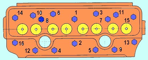
Cylinder head tightening order and tightening force
The mounting bolts are tightened with a torque tool in accordance with the diagram given in the technical documentation. The algorithm for tightening the head bolts is identical for naturally aspirated engines and units equipped with supercharging. The fasteners are first tightened with a force of 70-90 N/m, and then the second stage of fixation is carried out with a torque of 170-190 N/m (step-by-step tightening is used only for the diesel version with a turbocharger). Between steps there is a pause of 5-6 minutes, necessary for uniform deformation of the gasket.
The final fixation of the parts is carried out with a force of 190-210 N/m (atmospheric model) or 230-250 N/m (supercharged version); applying more force is strictly prohibited.
If at least 1 fastening element rotates in the body of the block or the rod breaks (or the head breaks), then you will need to dismantle the head and restore the thread. Operation of the motor with a damaged head mounting element is not allowed.
Tightening the cylinder head bolts of the D-240 engine
The tightening of the cylinder head bolts should be checked after 40 t km and in those cases after installing the cylinder head during engine repairs, and after a couple of days of operation, to allow for shrinkage of the cylinder head gasket. If this is not done, then the cylinder head gasket may burn out and coolant may still leak into the engine sump.
We tighten the bolts on a warm engine, approximately 60 degrees in the following order.
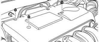
Tightening the cylinder head bolts
- Unscrew the top valve cover.
- We unscrew the rocker arm axle (don’t forget about the oil supply).
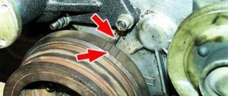
- Check the tightness of all cylinder head bolts with a torque wrench in a specific sequence, as shown in the figure. The tightening torque with a wrench is 220-10 Nm. After tightening the cylinder head bolts, reinstall the rocker arm axle and tighten the struts. Next, adjust the valve clearances.
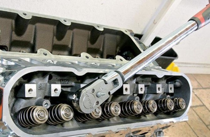
Torque wrench
You can adjust the valves yourself. It is necessary to adjust the valves on the engine in some cases. This is done after each removal of the cylinder head, after 480 hours of engine operation, after pulling the cylinder head, when knocking valves, after running in a new engine, and timely engine maintenance.
Adjustment of the MTZ engine valves must be done on a warm engine at 60-40 degrees. Before making adjustments, be sure to tighten the rocker shaft mounts. The operation of your engine, its durability, and fuel consumption depend on proper valve adjustment.
Adjusting valves in the D-245 engine
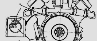
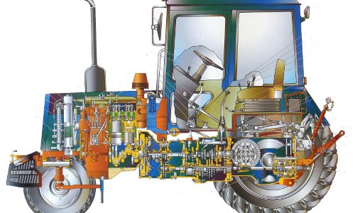
Before you start setting up the D-245 valves, you need to study the features of this unit. The shaft has 5 supports and is driven by the crankshaft and distribution gears. 5 bushings are used as working bearings, which are placed in sections of the block. The front bushing is located in the fan area and is equipped with a collar that secures the camshaft axial shifts; the others are made of cast iron. The steel pushers are overlaid with special cast iron, and the spherical surface has a radius of 750 mm. Angled camshaft cams.
To correctly adjust the D-245 valves, it should be taken into account that the pusher rods are made of steel rod and have a spherical area that fits into the pusher. The valve rocker arms were made of steel, and the axle was fixed using 4 racks. The axis is hollow, equipped with radial holes for oil delivery.
Characteristics
Before studying the valve adjustment on the D-245 engine, let’s consider its technical parameters:
- Manufacturer: MMZ (Minsk).
- Type - four-stroke in-line diesel engine with an in-line arrangement of 4 cylinders.
- The fuel mixture is supplied by direct injection.
- Compression – 15.1.
- Piston displacement – 125 mm.
- The cylinder diameter is 110 mm.
- Working volume – 4.75 l.
- Cooling is a liquid system.
- Speed – 2200 rotations per minute.
- Average fuel consumption is 236 g/kWh.
- Power indicator – 77 kW.
Modifications
The procedure for adjusting the D-245 valves is identical for all modifications of this series. Among them:
- D-245-06. This engine has a power rating of 105 horsepower, four cylinders, in-line arrangement, liquid cooling and free atmospheric intake. The model is installed on MTZ 100/102 tractors. As standard, the engine is equipped with an ST-142N starter, a G-9635 generator, as well as a pneumatic compressor, a gear-type pump, an oil pump and a paired disc clutch.
- D-245. 9-336. This diesel power plant has an in-line arrangement of four cylinders and turbine supercharging. The motor is installed on MAZ-4370 vehicles, equipped with a 24-volt starter 7402.3708, a compressor with a TKR 6.1=03-05 turbine, fuel, water, oil and gear pumps. The clutch is a single-plate clutch without a housing.
- D-245. 12C-231. The modification has a power of 108 “horses”, in-line cylinder arrangement, turbocharging. Diesel is mounted on ZIL 130/131. The engine is equipped with a PP4V101F-3486 fuel pump, a turbine and pneumatic compressor, and a single-plate clutch with a crankcase.
Adjustment
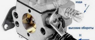
We will do the valve adjustment according to my simplified method, using an injection pump. To adjust, we need a tool, such as a 32mm wrench to turn the crankshaft, a 14mm wrench to tighten the rocker arm lock nut, a screwdriver, a feeler gauge, a 19mm wrench.
Remove the top valve cover and unscrew the high pressure pipes to the injection pump. Using a 32 wrench, we turn the crankshaft by the pulley bolt and look at the top of the injection pump where the diesel fuel comes out, which means that is where the TDC of this cylinder is. Next, it’s a matter of technique, loosen the lock nut by 14 with a wrench, install the dipstick and make adjustments with a screwdriver. The dipstick should move snugly between the valve and the rocker. The gaps are as follows; 0.25 inlet, 0.30 inlet. The operating order of the cylinders is 1,3,4,2. In this way we adjust each cylinder of the engine in turn.
WATCH THE VIDEO
ignition adjustment d 245 euro 2
Checking and adjusting the setting angle of fuel injection advance on a diesel engine
In case of difficulty starting a diesel engine, smoky exhaust, as well as when replacing and installing a fuel pump after testing at the stand through 6TO-2 or repair, be sure to check the setting angle of advance of fuel injection on a diesel engine. Checking the setting angle of injection advance fuel with a type 833 fuel pump in the following sequence: - set the piston of the first cylinder on the compression stroke 40° - 50° before TDC; - connect a voltage of 68 V (current 34A) to the STs 5.501.202 connector of the injection pump actuator for a system with on-board voltage 24V and 34V (current 6.8A) for a 12V system. “-” to pin 2 (black actuator wire) and “+” to pin 3 (white wire). The fuel injection pump rack will move towards maximum flow. To avoid short circuits when supplying voltage, it is advisable to use a socket STs 5.601.202; - disconnect the high-pressure tube from the fitting of the first section of the pump and instead connect a control device, which is a piece of high-pressure tube 100 to 120 mm long with a pressure nut at one end and the other end bent to the side from 150° to 170° in accordance with Figure 1
Figure 1 - Sketch of the control device 1-press nut; 2-high pressure pipe fill the fuel pump with fuel, remove air from the low pressure system and create excess pressure with a manual priming pump until a continuous stream of fuel appears from the control device tube; slowly rotating the diesel crankshaft clockwise and maintaining excess pressure in the pump head (booster pump ), monitor the flow of fuel from the control device. At the moment the fuel flow stops (up to 1 drop is allowed to drop in 10 seconds), stop rotating the crankshaft; unscrew the lock from the threaded hole of the rear sheet in accordance with Figure 2 and insert it with the back side into the same hole until it stops in the flywheel, while the lock should coincide with the hole in the flywheel (this means that the piston of the first cylinder for diesel engines D-245.7E3 and D-245.9E3 is installed in a position corresponding to 20-4° before TDC).
Figure 2 - Installing the lock into the hole in the back sheet and flywheel. If the lock does not match with the hole in the flywheel, make an adjustment by doing the following: remove hatch cover 1 in accordance with Figure 3; align the lock with the hole in the flywheel, turning in one direction or the other crankshaft; loosen nuts 2 fastening the fuel pump drive gear 6 by 1 - 1.5 turns; using a wrench, turn the fuel pump shaft counterclockwise by the special nut 4 until the pins 3 rest against the edge of the groove of the fuel pump drive gear; create excess pressure in fuel pump head until solid
filesclub.net