Purpose of power steering
Before studying in more detail the structure of the MTZ 80 steering column, as well as possible malfunctions of this important unit, it is advisable to become more familiar with its purpose and features. Power steering of MTZ tractor equipment is designed to reduce the driver’s efforts required to perform maneuvers when driving a vehicle.
If you study the design of the tractor, you can conclude that this unit appears to be intermediate between the steering wheel and the wheels of the tractor. All steering components, as well as hydraulic elements, are installed under the radiator.
Power steering MTZ-80
List of nodes
When planning to figure out how to repair the MTZ 80 steering column with your own hands, you should study the design of this component. The power steering is equipped with a separate hydraulic system, which does not depend on similar elements that are part of the internal structure of the tractor.
The main elements of the steering hydraulic system are a distributor, metering and cylinder pumping devices, as well as a sensor for automatically locking the rear axle of the vehicle. Considering the design of the hydraulic booster in more detail, it is necessary to mention the following important elements:
- the housing where the oil tank is located serves for mounting most of the power steering parts and elements;
- a pump that makes it possible to move oil in the hydraulic system;
- the sector in contact with the steering is located on the rotary shaft;
- rotary shaft equipped with 3 support elements;
- a rack that transmits the movement of the piston to the sector;
- a spool mounted on one of the ends of the worm gear of the steering column;
- a filter used to clean the oil circulating in the hydraulic system;
- a safety valve, the main purpose of which is to protect the unit from excessive pressure.
If you want to know how to troubleshoot the steering column, you need to pay attention to another important design element - the automatic locking system. It is designed to lock the rear axle differential and includes several components.
Possible faults
The products of the Minsk Tractor Plant are of high quality, excellent technical characteristics and long service life, but over time they may require repairs and adjustments. Owners of MTZ tractors have to deal with several typical power steering breakdowns, which include:
- tight steering;
- the tractor does not turn in the right direction;
- There are delays in the operation of the node.
To eliminate such faults, it is strongly recommended to disassemble the unit and troubleshoot individual elements, and then replace the damaged parts with new ones. After carrying out the work, you will need to install the unit in place, and then adjust it.
Steering column diagram
Setup and repair
If it is necessary to improve the power steering MTZ 80 or eliminate minor damage, it is enough to perform a detailed adjustment of this mechanism. To do this, it is advisable to adhere to the following instructions:
- Loosen the main bolt located at the worm-sector engagement point.
- Using a wrench, turn the bushing clockwise until it stops, then turn it in the opposite direction by 1-1.2 cm.
- Tighten the main bolt, start the engine and make sure the steering wheel rotates correctly.
- If binding is detected, you will need to increase the engagement gap by turning the bushing counterclockwise.
- Adjust the sector-rail connection by reducing the thickness of the adjusting shims until they stop. The extreme position can be determined by the gap between the rail and the stop, which will reach 0.1-0.3 mm.
- Tighten the thrust bearings using a ball nut, being careful not to over-tighten them.
In addition to adjusting the unit, maintenance may need to be performed to help keep the power steering in optimal condition. Most often, it is necessary to wash the oil filter, which can be done by lifting the lining, dismantling the oil line and cover.
Some breakdowns, such as difficulty turning, may indicate insufficient fluid volume in the hydraulic system, improper adjustment, or worn cylinder o-rings.
Measures to repair hydraulic steering mechanisms of a tractor seem to be quite complex and require special equipment to monitor performance indicators. In some cases, it may be easier to install the MTZ 80 power steering assembly, which will avoid problems with finding broken elements. To do this you will need:
- Make sure the oil supply system is tight.
- Install the assembled mechanism on special bushings located on the front beam of the semi-frame.
- Mount the steering shaft into the column, as well as install other elements.
Purchasing an assembled hydraulic booster seems to be a much more expensive solution than sequential adjustment and troubleshooting of its parts, but it allows you to quickly solve problems that have arisen.
Maintenance of steering control MTZ-80, 82
______________________________________________________________________________________________
Safety, quality of work and driver fatigue largely depend on the condition of the steering control of the MTZ-80, 82 tractor. Therefore, steering maintenance must be carried out especially carefully. Maintenance of the steering consists of periodically monitoring the oil level in the power steering housing and replacing it, lubricating the universal joints of the steering drive, monitoring the condition of the threaded connections of the steering drive and steering rods, bipod and swing arms, fastening the sector, checking and adjusting the free play of the steering wheel. The steering column must be adjusted to eliminate possible vibrations on the steering wheel.
To do this, tighten nut 12 by hand (see Fig. 1) until the latter comes into contact with sleeve 10. In this case, the gaps in the connections must be selected. Then unscrew nut 12 one and a half turns and lock it with nut 13.
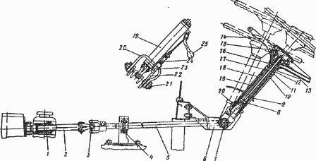
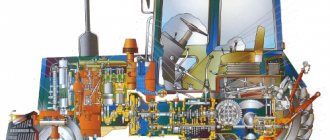
Rice. 1. Steering gear drive MTZ-80, 82 1 - splined bushing; 2 - front shaft; 3, 7 — cardan joints; 4 - intermediate support; 5 - middle shaft; 6 - stand; 8 — pin; 9, 12 — nuts; 10 - bushing; 11 — shock absorber; 13 - lock nut; 14 — steering wheel; 15 — handwheel; 16 — steering shaft; 17, 21 — screws; 18 — intermediate shaft; 19 — steering column pipe; 20 — earring; 22 — right wall stand; 23 - retainer; 24 - spring; 25 – handle The oil filter is washed in the following sequence:
— Raise the cladding.
— Disconnect the oil supply line 12 (see Fig. 2) from the cover 11 of the pressure reducing valve 14.
— Remove the cover, for which you first unscrew the two bolts securing it to the body 22, and then, using them as dismantling ones, screw the bolts into the dismantling holes of the cover and remove it.
— Disconnect the remaining oil lines from pressure reducing valve 14.
— Holding filter 13 with your hand, turn out the pressure reducing valve and remove the drain filter.
— Wash the filter in diesel fuel.
To install the filter, perform the operations in reverse order:
— The filter is washed at TO-3 (960-1000 operating hours).
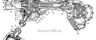
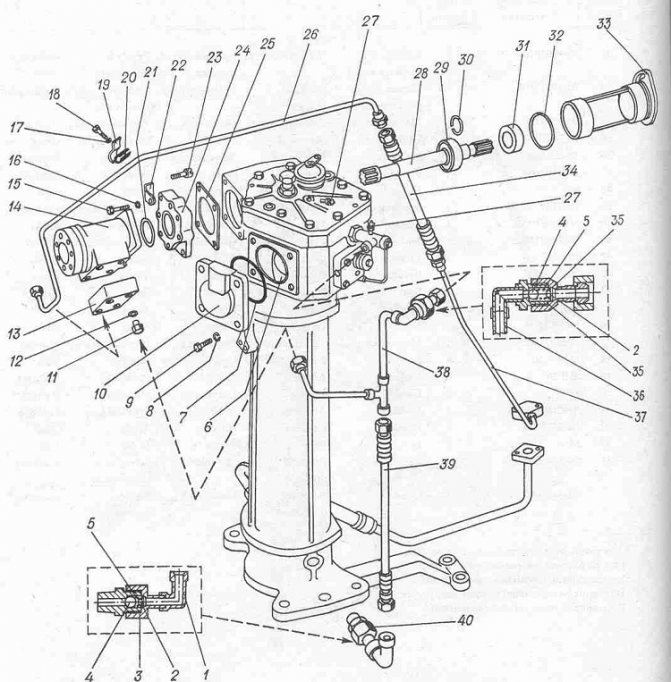
— At the same time, you need to tighten the nut 8 securing the sector on the rotary shaft. Rice. 2. Power steering power steering of the MTZ-80.82 tractor 1 - plug; 2 valve cover; 3 valve adjustment screw; 4 worm; 5 — bolt for fastening the adjusting sleeve; 6 — adjusting sleeve; 7 - sector; 8 - nut; 9 - rack; 10 — adjusting bolt; 11 — top cover; 12 - nut; 13 — drain filter; 14 - pressure reducing valve; 15 — ABD control valve; 16 — differential lock sensor spool; 17 — control valve handwheel; 18 — bipod; 19 — bipod nut; 20 - drain plug; 21 - rotary shaft; 22 — body; 23 — rack stop; 24 — adjusting shims; 25 - rod; 26 - piston; 27 — front cylinder cover; 28 — thrust bearing; 29 — washer; 30 - spherical nut; 31 - spool Adjusting the power steering MTZ-82, 80 Check the worm-sector and sector-rack engagement, the tightening of the worm nut, the axial stroke of the rotary shaft, the safety valve, as well as the control of the differential lock valve.
The “worm-sector” engagement and the tightening of the power steering worm nut MTZ-80, 82 are adjusted in the following sequence:
— Jack up the tractor so that the front wheels do not touch the ground. — Then loosen the tightening of the adjusting bolt 5, insert a key into the groove of the sleeve 6 and turn it clockwise until the teeth of the worm and the sector stop (in this case, the bipod 18 should be in the middle position).
— The bushing is turned counterclockwise so that it rotates 10-12 mm along the outer diameter. Tighten bolt 5.
— Start the engine and check that there are no jams in the worm-sector engagement when turning the steering wheel in both directions until it stops. — If jamming occurs, then you need to increase the gap in the engagement by releasing bolt 5 and turning sleeve 6 additionally clockwise. The force on the steering wheel should not exceed 30-40 N.
Adjusting the tightening of the spherical nut 30 of the power steering worm consists of correctly tightening the thrust ball bearings 28 to ensure that the ends of the spool 31 are normally pressed by the bearing rings. The correct operation of the MTZ-80, 82 power steering largely depends on the correct adjustments.
Excessive tightening of nut 30 may cause spool misalignment and increased turning force.
The gaps between the bearings and the spool lead to an increase in the free play of the steering wheel, as well as to vibrations of the wheels, since under these conditions the spool can move arbitrarily, accordingly changing the direction of oil flow into one or the other cavity of the piston cylinder. Before tightening the nuts 30, unscrew the four bolts securing the distributor, remove the cover 29. Fasten the distributor with two diametrically located bolts to the power steering body, placing a set of washers (or a nut) under the heads of the bolts, the thickness (or height) of which is equal to the thickness of the cover flange 29.
Tighten, having previously uncoiled, the nut with a torque of 20 Nm. In this case, the bearing rings 28 must be tightly pressed to the ends of the spool 31. Then unscrew the nut 1/10-1/12 of a turn to align the slot of the nut for the cotter pin and the hole in the worm, and cotter the nut.
Unscrew the two bolts screwed into the housing, replace the cover 29 and secure the distributor. The “sector-rack” engagement of power steering MTZ-82, 80 is regulated by gaskets 24 under the flange of the rack stop 23.
In this case, the gap between the stop and the rail 9 should be 0.1-0.3 mm. When checking this gap, you need to press rack 9 towards sector 7. The axial stroke of the tractor rotary shaft is adjusted in the following sequence:
— Loosen the locknut and screw the adjusting screw 10 all the way into the end of the shaft. Then unscrew the bolt 10 pa 1/8-1/10 turn and lock it with a nut. — The safety valve is checked as follows. Instead of plug 1, a pressure gauge with a division scale from 0 to 10 MPa is connected to the discharge line or to the valve cover.
— Start the engine and turn the steering wheel from one extreme position to another. At maximum rotation speed of the diesel crankshaft, bring the oil temperature in the hydraulic system to 50±5°C. In this case, the pressure should reach 8.8 MPa. If the pressure gauge readings are less, increase the pressure to the required values by slowly screwing in screw 3. After adjustment, screw 3 must be secured with a nut and the cap installed.
A sign of a violation of the adjustment of the safety valve of the MTZ-80, 82 hydraulic booster is an increase in force on the steering wheel. The free play of the steering wheel is checked when parked with the engine running. However, it should not exceed 20°.
If the free play of the steering wheel is greater, check the gaps in the connections of the steering drive and, if necessary, tighten the nuts securing the bipod and sector, fastening the swing arms of the front axles and steering linkage joints, tightening the worm nut, adjusting the “worm-sector”, “sector-rack” engagement. and axial travel of the hydraulic booster rotary shaft. It is necessary to monitor the oil level in the steering hydraulic system. If the oil level is below the lower mark on the oil gauge, operating the tractor is strictly prohibited. When changing the oil, the filler filter must be washed at the same time. After changing the oil, pump the hydraulic steering system of the MTZ-80, 82 tractor in the following order: - Jack up the front axle until the front wheels lift off the ground.
— Start the engine and, at a low engine speed, turn the steering wheel to the extreme positions 8-10 times (first slowly, then quickly), without holding it in the extreme positions.
— Then check the oil level and, if necessary, add it to the upper mark of the oil gauge. The distributor has to be removed and reinstalled if its O-rings are replaced and parts are washed. When installing the distributor, do the following. Check the presence of sealing rings at the ends of the distributor and the position of spool 31 in its body.
The spool must be installed so that its chamfered end along the outer diameter is directed towards the power steering housing. Setting the spool in the opposite direction will result in a sharp increase in turning force. Install the distributor without the outer cover 29 and secure it to the power steering housing with two diametrically located bolts, placing a set of washers under the bolt heads, the thickness of which is equal to the height of the cover.
Install the thrust bearing 28, a washer with a cone and tighten the spherical nut 30 in accordance with the recommendations given above. A sign of correct tightening of the nut is the absence of gaps between the spool and the bearing rings and the steering wheel recoil (return of the spool to the neutral position) after it stops rotating to the left.
______________________________________________________________________________________
___________________________________________________________________________________________
Other special equipment
MTZ-80
- Creeper MTZ-80, 82
- Design of the chassis of the MTZ-80 tractor
- Gearbox MTZ-80
- Clutch MTZ-80, 82
- Maintenance and adjustment of the MTZ-80.82 gearbox
- Starting motor PD-10
- Transfer case MTZ-80
- Adjustments of drive axles MTZ-80, 82
- Steering gear and power steering MTZ-80, 82
- Braking system MTZ-80, 82
- PTO MTZ-80, 82
______________________________________________________________________________________
YaMZ-236
- Components of the YaMZ-236 HE2, BE2 cylinder block
- Clutch YaMZ-181,182,183
- Clutch discs YaMZ-236, 238
- Crankshaft and piston group YaMZ-236
- Gearbox YaMZ-236
- Diagnostics and adjustment of the YaMZ-236 engine
- Fuel supply and lubrication of the YaMZ-236 diesel engine
- Clutch YaMZ-236
- Injection pump and injectors YaMZ-236
YaMZ-238
- Cylinder block and piston group YaMZ-238
- Crankshaft and timing belt of diesel engine YaMZ-238
- Gearbox YaMZ-238
- Cooling and lubrication of diesel engine YaMZ-238
- Clutch YaMZ-238
- Fuel injection pump YaMZ-238
T-130
- Onboard clutches T-130
- Final drive T-130
- Diesel D-160 tractor T-130
- Undercarriage T-130
- Turning mechanism of the T-130 tractor
- Assembly and installation of T-130 trolleys
- Servomechanism of onboard clutches T-130
- Tractor clutch T-130
- Control mechanism for clutch and mountain brake T-130
T-170
- D-180 engine of T-170 bulldozer
- Hydraulic system of bulldozer T-170
- Hydraulic cylinder of bulldozer T-170, 130
- Repair of the main gear of bulldozer T-170, 130
- Tracks and rollers T-170, 130
- Carrying and running system T-170
- Assembly of gearbox units T-170, 130
- Tension mechanism and support roller T-170, 130
- Bulldozer equipment T-170 with rotary blade
- Adjusting the T-170 clutch
- Transmission parts for bulldozer T-170
KRAZ
- Gearbox KRAZ-255, 260
- Steering of Kraz-250, 255
- Drive axle and cardan shafts Kraz-255, 260
- Clutch Kraz-250, 260
- Power steering of the Kraz car
- Kraz car suspension
- Kraz transfer case
- Kraz power take-off
- Brake system for Kraz-6510, 65055 vehicles
- Cardan transmission and drive axles Kraz-6510, 65055
- Front suspension of Kraz-6510, 65055 cars
- Steering KRAZ-6510, 65055
- Clutch Kraz-6510, 65055