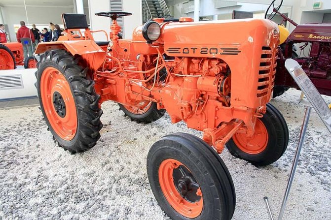
Tractor DT-20: history
The tractor of the Kharkov Tractor Plant (KhTZ) DT-20 was produced from 1958 to 1969. During this time, more than 200,000 cars were born. The equipment became the product of a comprehensive redesign of the DT-14B model. The following have been revised:
- motor power;
- number of teeth on gears;
- design of body parts;
- main gear housing device.
To improve the machine's performance, a pedal was added that simultaneously activates both brakes.
Tractor DT-20: technical characteristics
DT-20 belongs to the 0.6 traction class of small-sized special equipment. The model was equipped with a factory D-20 engine. The 18-horsepower engine ran at 1600 rpm and accelerated the car to 9.5 km/h. With a relatively small mass of almost two tons, the equipment created a specific pressure on the ground equal to 0.42 kg/cm2.
The maximum turning radius of the DT-20 tractor was 780 mm. Ground clearance of 250 mm made it possible to overcome various obstacles during agricultural work. The specific fuel consumption of a small-sized car was 200 g/hp*h.
Dimensions:
- length - 2818-3038 mm;
- width - 1300 mm;
- height - 1231-1438 mm.
Tractor DT-20: engine
The factory DT-20 engine deserves special mention. The base model was equipped with an improved D-20 power unit. Standard engine power is 18 hp. at 1600 rpm increased to 20 hp. when the speed increases to 1800 per minute. Like the tractor itself, the engine was a continuation of the modernization of its predecessor D-14V. The compression ratio of the new unit was 15. The launch was carried out using an electric starter. In comparison with the previous engine, the D-20 received:
- new crankcase side walls. The design of this part had to be revised due to the changed size of the crankshaft crank mechanism;
- new cylinder head and crankcase. In the crankcase, the dimensions of the bores for the balance bearings have increased. Changes were made due to increased engine speeds, which required a new design of other associated parts;
- rubber breather valve.
The changes made affected some significant characteristics of the motor. Thus, the engine filling ratio and the efficiency of air use in the pistons have increased. The piston chamber enlarged during the modernization process had a positive effect on the performance of the power unit. Fuel efficiency has also increased, which in turn has optimized fuel consumption.
Transmission
The power transmission of the DT-20 tractor consisted of:
- coupling;
- clutches;
- rear axle with differential;
- final drive to the rear axle.
With this device, the car could move at four forward speeds and the same number of reverse gears. Additionally there was a fifth low gear.
Tractor DT-20: device
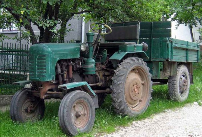
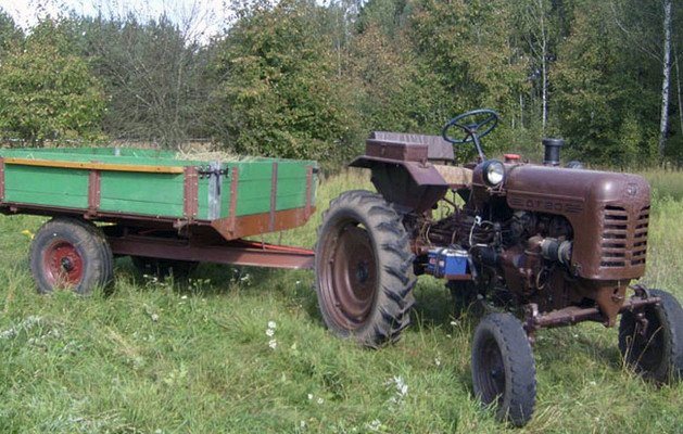
DT-20 belonged to the classic version of the tractor for its time with one drive axle. The rear-wheel drive car used rear tires of increased size and reduced pressure with a pronounced off-road pattern. The front axle was steering and used smaller radius tires with a road tread pattern.
The variable characteristics of the chassis made it possible to adapt the tractor to various types of work. The wheel track, longitudinal wheelbase, ground clearance and adhesion weight significantly influenced the dynamic characteristics of the machine and its performance. The DT-20 was easily converted for use in reverse. An interesting feature of the car: the steering wheel, pedals and seats could be rearranged, and the wheels could be swapped.
The machine used a dependent power take-off shaft, mounted hydraulic system, mounted system for implements and a replaceable pulley. In a unit with a canopy, the tractor's load level on the main wheelbase changed. The brake system was equipped with pedal control.
A classic representative of the Soviet era, the DT-20 tractor offered maximum efficiency and minimum comfort. There was no cabin on the car. If desired, it was possible to purchase separate models equipped with an awning. Although this was rare.
Specifications
Main technical features of the DT-20 tractor
| Characteristics | Indicators |
| engine's type | Diesel |
| Specific ground pressure | 0.046 kg/cm2 |
| Hook pull force | 0.125-0.72 t |
| Initial driving speed at 1600 rpm | 5.03 km/h |
| Maximum driving speed at 1600 rpm | 15.6 km/h |
| Maximum driving speed at 1800 rpm | 17.65 km/h |
| Additional gear at 900 rpm | 0.87 km/h |
| Initial engine power | 13.2 kW |
| Starting speed | 1600 rpm |
| Maximum speed | 1800 rpm |
| Number of engine cylinders | 1 PC. |
| Cylinder diameter | 12.5 cm |
| Piston stroke | 14 cm |
| Maximum tank volume | 45 l |
| Specific fuel consumption | 200 g/hp at one o'clock |
| Track type | adjustable |
| Front track dimensions | 1.1-1.4 m |
| Maximum length of longitudinal base | 1.63-1.775 m |
| Minimum length of longitudinal base | 1,423-1,837 m |
| Maximum clearance | 0.515 m |
| Minimum clearance | 0.308 m |
| Total weight | 1.56 t |
| Overall width at track 1.1 m | 1.31 m |
| Maximum height in hood area | 1,231 m |
| Minimum height in hood area | 1,438 m |
| Maximum length (with canopy) | 2.818-3.038 m |
Video: review of the DT-20 tractor
Dimensions and weight
The DT-20 tractor has quite miniature dimensions. The nominal dimensions of the machine are 2818 mm x 1300 mm x 1231 mm, maximum 3038 mm x 1300 mm x 1438 mm. At the same time, the complete absence of a frame significantly lightened its weight, since it does not exceed more than 15,600 kg.
Important! The design of the DT-20 tractor does not provide brackets for mounting ballast weights, which are necessary for adhesion of pneumatic tires to the ground. This shortcoming is partially eliminated by filling the pneumatic with water.
Engine
The tractor has a four-stroke engine consisting of one cylinder . Cooling type: circulating, tap water is used as a coolant. An electric starter is provided to start the engine.
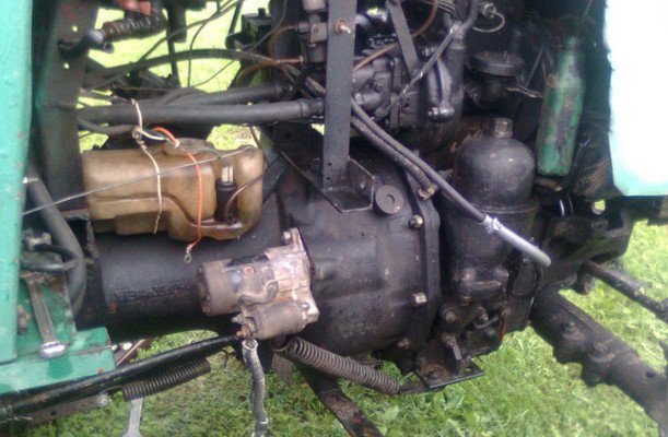
The motor has a unique mechanism that reduces vibration. It consists of two shafts parallel to the crankshaft, balanced by a counterweight. The fuel pump is simple, single-section.
Transmission
The transmission of the DT-20 is simple, mechanical . Between the motor and the gearbox there is a friction clutch consisting of a single disc. It does not close while the tractor is running. The control knob helps control this clutch.
The transmission has 4 gears, as well as the ability to reverse . The maximum speed does not exceed 15.7 km/h, but when the engine speed increases to 1800 rpm, the speed increases to 17.65 km/h.
Important! When the engine is constantly running at high speeds, its wear increases significantly, so it is worth accelerating the engine to no more than 80% of the maximum power.
Chassis
The DT-20 chassis consists of the following parts:
- wheels and front axle;
- rear drive axle and wheels;
- vertical steering column;
- worm gear steering with double roller;
- brake system.
Attachments
Any units that have a trailing mechanism, which can be controlled using a hydraulic system, can be used as auxiliary field equipment for the DT-20. The most frequently used among them are the following:
- pick-up LNV-1.5;
- transporter PAV-000;
- sprayer ONK-B;
- pollinator OSHU-50;
- dragging machine AVN-0.5;
- loading platform PVF-0.5.
Important! It is not recommended to purchase modern equipment for working with the DT-20 tractor, since such devices are often technically incompatible with the unit.
Interesting Facts
The DT-20 tractor is on display in several mechanization museums. These include the Saratov open-air exhibition on Sokolova Gora, the museum in Tartu (Estonia), the Museum of Architecture and Life of the Middle Dnieper and the Cheboksary Tractor Museum. The DT-20 was featured on a series of matchstick labels alongside other legendary car models.
After the DT-20 was discontinued, it was replaced by the T-25 tractor, similar in functionality, but greatly superior to its predecessor in technical characteristics.
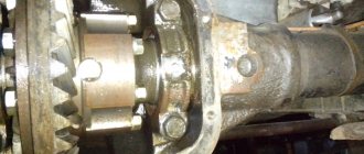
MAIN TRANSMISSION OF THE DT-20 TRACTOR - PART 2
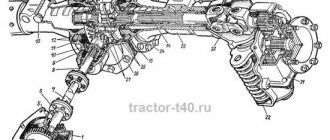
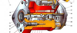
At the bottom of the main transmission, under the intermediate and main shafts, there is an additional transmission unit (Fig. 81). The drive roller 5 of the additional gear is located along the axis of the tractor, parallel to the input shaft of the main gear, and rotates in two radial ball bearings 7 and 10. In the front part of the drive roller, a constant meshing gear 1 of the additional gear is installed on splines. The gear is seated all the way into the spring retaining ring 8 on the drive shaft.
The inner ring of the front bearing 7 is placed on the cylindrical end of the shaft, and the outer ring is pressed into the bearing seat 3 until it touches the shoulder. A retaining spring ring inserted into the annular groove of the socket secures the bearing ring from axial movements. The bearing seat is installed in the bore of the front wall of the main gear housing, closed with a flat cover and attached together with it to the crankcase. Adjusting shims 2 are placed under the socket flange in the crankcase recess.
Rice. 81. Additional (slow) gear drive:
I — driven gear of constant mesh; 2 — adjusting shims; 3 - bearing seat; 4 - cover; 5 — drive roller of additional transmission; 6 - thrust ring; 7 - ball bearing; 8 and 9 — retaining spring rings; 10 — bearing; 11 — driving bevel gear of additional transmission; 12 — retaining spring ring; 13 — power take-off shaft; 14 — driven bevel gear of additional transmission; 15 — bearing; 16 — retaining ring; 17 — movable gear of additional transmission; 18 — retaining ring; 19 — bearing; 20 — bearing cup; 21 — adjusting shims; 22 - cover; 23 — retaining ring
A thrust ring is installed between the gear hub 1 and the inner ring of the bearing. In the middle part of the drive roller, between two retaining spring rings 9 and 12, there is a bearing 10, and on the splines of the roller there is a driving bevel gear 11 of the additional gear. The outer bearing ring is mounted in a boss inside the final drive housing. The free splined end of the drive shaft of the additional transmission is connected by a splined sleeve to the power take-off shaft 13.
The driven bevel gear 14 of the additional gear is made together with a splined shaft and rotates on two ball bearings. The inner bearing 15 is installed in a boss inside the crankcase and secured to the shaft near the bevel gear with a retaining spring ring 16. The second bearing 19 is installed on a shaft between two retaining rings. The outer ring of this bearing is located in cup 20 of the main gear housing.
The cup cover 22 clamps the outer ring of the bearing and closes it. It is attached together with the glass to the main gear housing. Adjusting shims 21 are placed under the flange of the cup 20. By changing the number of shims 2 and 21, the gap between the teeth of bevel gears 11 and 14 is adjusted.
Spur gear 1 of drive roller 5 is in constant mesh with spur gear 8 (Fig. 78) of the main gear input shaft and rotates in one direction. Together with gear 1 (Fig. 81), the drive shaft and bevel drive gear 11 rotate, with which the driven bevel gear 14 is in constant mesh. A spur gear 17 with an annular groove for the shift fork is freely mounted on the splined part of the shaft of this gear. This gear, when moving along the shaft splines, meshes with spur gear 39 (Fig. 78) of the first gear, located on the main shaft. When the additional gear is engaged, rotation from the engine is transmitted through the constant mesh gears to the drive shaft 5, bevel gears 11 and 14, drive gear 17 and to the driven gear of the first gear of the main shaft (Fig. 81). From the main shaft, rotation is transmitted to the differential and drive wheels of the tractor. The speed of the tractor in this case will be very low, so the additional transmission unit is not designed to operate a tractor with a traction force of more than 700 kg. The additional gear is activated by moving the movable gear on the additional gear shaft. The reverse is switched by moving the gear coupling of the reverse mechanism on the gear sleeve.
To move the carriages and gears, gear shift forks mounted on the shift rollers are used (Fig. 82).
The lower ends of the forks freely fit into the annular grooves on the gears, carriages and on the gear coupling of the reverse mechanism. The shift rollers are located above the intermediate and main shafts and move in the holes in the side walls of the main gear housing. The ends of the rollers emerging from the main gear are covered with covers 12. The shift forks, as well as additional guides, have slots into which the ball end of the gear shift and reverse levers fits. The front roller 1 is equipped with a fork 2 for shifting the first and fourth gears, made together with a leash. Fork
secured to the shaft with a bolt 11, which tightens the fork hub on the shaft, and the cylindrical part fits into the recess of the shaft.
Roller 4 has a driver 3 of the second and third gears and a fork 5. On the shaft 6 there is a fork 10 for engaging the additional gear, and on the roller 8 there is a fork 9 for switching the reverse and a driver 7 of the reverse shift roller. To hold the gears in the off or on positions, the rollers at the right ends have recesses into which conical stops or locking mechanism detents fit. There are three indentations on the shift rollers for first and fourth, second and third gears. The middle ones are designed to fix the rollers in the off, or neutral, position. The extreme recesses fix the engaged position of the gear. There are two grooves on roller 6, since they only engage one gear.
Rice. 82. Shift rollers and forks:
On the reverse activation roller 8 there are also two recesses that fix
the position of the clutch fork of the reverse mechanism when turning on the reverse to move forward or backward.
The locking mechanism (Fig. 83) consists of a housing 6 and a roller 1, the latter can move in the housing along the axis of the tractor above the shanks of the clamps. There are holes made on the cylindrical part of the roller into which the cylindrical shanks of the clamps fit. Clamps 4, equipped with conical heads and cylindrical shanks, are inserted into the holes of the main gear housing in the right front part. The shanks fit into the holes of the locking housing 6, and the housing mounted on the main gear housing closes the clamps with springs 5. They press the clamps against the gear shift rollers. The clamps, falling with their conical part into the recesses of the shift shaft, fix it and the fork in a position corresponding to the complete engagement or disengagement of the gear. This eliminates the possibility of turning on and off the gears and the reverse gear clutch while driving with the clutch engaged, as well as the spontaneous disengagement of the gears and the reverse gear clutch under load while the tractor is moving.
Rice. 83. Locking the gear shift and reverse mechanism: 1-valve lock; 2— felt seal; 3 - lock bolt; 4— latch; 5—clamp spring; 6 — blocking body; 7 - spring ring.
To limit the stroke of the locking roller and keep it from turning, use a locking bolt 3, the shank of which fits into
longitudinal groove of the roller. Felt seal 2 installed in the locking body protects parts from contamination. The oil seal is held in the housing by a washer and a spring ring 7. The shaft has holes for a rod connecting it to the clutch control lever.
When the clutch is engaged or when it is not completely disengaged, the holes in the locking body, into which the cylindrical shanks of the clamps fit, are blocked by the locking roller 1. Therefore, the clamps cannot rise up from the recesses of the shift rollers; the latter will not move and engage or disable gears or shift the reverse clutch. Moving the rollers, engaging gears or changing reverse is possible only when the clutch is disengaged. In this case, the locking roller will move forward and the holes in it will be located above the cylindrical shanks of the clamps. When moving the shift roller, the lock will come out of the roller recess and its shank will fit into the hole of the lock roller. If the gears of the engaged transmission are not fully engaged, the lock will not completely lower into the recess on the roller, the cylindrical shank of the lock will not come out completely from the hole of the locking roller and it will not be able to move along the axis. Therefore, the clutch control lever cannot be moved to engage the clutch.
To change gears and reverse, use a mechanism (Fig. 84) mounted in the top cover of the main gear. On the left side of cover 1 there is a gear shift lever 7. It is welded to gear shift shaft 3 and together with it can move and rotate in the holes in the top cover. The inner lever 4 is secured to the shaft inside the cover with a coupling bolt 9 and a key 11.
gear shift. Its ball head fits into the slots of the forks and the driver of the gear shift rollers.
Rice. 84. Top cover with gear shift and reverse mechanism:
1- top cover of the main gear; 2 - filler plug; 3 — shaft of the gear shift lever; 4 — gear shift lever; 5 — felt seal; 6 — reverse switch lever; 7 — gear shift lever; 8 - drawstring; 9 — coupling bolt; 10 — reverse switch lever; 11 - key; 12 - ball; 13 - plug; 14— spring; 15—reverse switching roller; 16—installation bolt; 17 — felt seal; washer.
By moving lever 7 with the gear shift roller along the tractor, the ball head of lever 4 can be installed in the slot of one of the drivers of the first three gear shift rollers. By turning the shift shaft, you can use the internal lever to move the shift shaft to the side to engage the gear.
The gear shift mechanism includes a slide 8 with slots for the lever, limiting its movement. This slide prevents two rollers from moving at the same time and, therefore, two gears being engaged. When the roller with the levers is moved forward until it stops in the rocker, the internal lever will be installed against the transverse slots of the rocker located above the shift roller for the first and fourth gears. This way, only first and fourth gears can be engaged. When the roller is moved back all the way, the lever will be positioned above the additional gear shift roller.
The position of the lever 4 against the slots of the slide above the shift roller for the second and third gears is fixed with a ball 12. With the force of the spring 14, it jumps into the annular groove of the roller and installs the lever above the roller for the second and third gears. Felt oil seal 5 prevents oil from leaking out and protects the main gear from contamination.
Long-term operation of the tractor in an additional gear under difficult conditions can lead to parts breaking. Therefore, the inclusion of an additional gear is prevented by a bolt sealed at the factory. It is screwed into the boss on the steering housing pipe so that the gear shift lever rests against the head of the bolt when the inner lever 4 is positioned against the transverse slots of the rocker above the shift shaft for the second and third gears. To use the tractor in an additional gear, remove the seal and screw in the bolt until it stops.
The reverse switch lever 6 is located on the right side of the top cover and is welded to the reverse switch roller 15. The roller rotates freely in the tides of the top cover. In its middle part, the reverse shift lever 10 is secured with a coupling bolt 9 and a key 11. The ball end of the lever constantly fits into the slot of the reverse shift roller driver. The locking or installation bolt 16 holds the roller from axial movements, and the felt gland 17 protects the main gear from contamination.
When lever 6 rotates the reverse shift roller, lever 10 moves the reverse fork to the forward or reverse position. The movement of the lever is limited by the walls of the hole in the crankcase cover.
The diagram of the positions of the gear shift handle is shown in Figure 84. On the top shift cover there are numbers cast, indicating the position of the handle in various gears, as well as the letters P (forward) and N (backward), indicating the position of the reverse handle for forward and reverse travel of the tractor.
The top cover has a platform and threaded holes for installing the seat when operating in reverse, as well as holes for filling oil into the main gear. The hole is closed with a conical breather plug. A hole is made in the upper boss of the cover for the shaft of the engine control foot pedal. An oiler is installed to lubricate the roller.
The main gear housing is closed on top with a cast iron cover 53 (Fig. 79), on which the shift link and the upper
cover 51 with gear and reverse levers. In the middle part of the cover there is a steering housing, and in the rear there is a bracket for the tractor driver's seat in forward motion. Holes are drilled in the cover to install the oil level indicator 54.
In front of the main gear, two steps are bolted: one on the left - to the crankcase cover, the second on the right - to the locking housing. A hydraulic lift is mounted on the rear wall of the main gear; brake hoses with final drives and brackets for the longitudinal rods of the mechanism for hanging machines and implements are attached to the side surfaces of the crankcase.
All internal parts of the main gear of the DT-20 tractor are lubricated by splashing oil poured into the main gear housing. Its level is controlled by marks on the dipstick screwed into the hole on the main gear cover. Oil is sprayed by the constantly rotating auxiliary gears and the differential driven gear.
Since the heavily loaded gears of the second gear are not sufficiently lubricated by splashing, for additional oil supply to them, a tray 48 with a reflector is installed on the front jumper inside the crankcase. Oil splashes formed during the rotation of the driven gear of the drive shaft of the additional gear are retained by the reflector, fall on the tray and are delivered to the teeth of the second gear gears. Lubricant is supplied to the hub bushings of the gears of the reverse mechanism and the rubbing surfaces of the differential side gears through the holes between the tooth cavities and through additional holes.
All covers are installed on cardboard gaskets, and self-moving rubber frame seals are installed on the ends of the shafts emerging from the main gear. To reduce the oil pressure on the intermediate shaft oil seal, a groove is made in the bearing cup through which the oil that has passed through the bearing is drained into the crankcase. Since during operation of the main gear, especially in hot weather, the pressure inside the main gear increases, it is necessary to relieve the oil seals and cardboard gaskets from the oil vapor pressure. For this purpose, the filler plug on the top cover of the main gear is made in the form of a breather 52, connecting the internal cavity of the main gear with the atmosphere. A thin wire is placed inside the plug to prevent dust and dirt from entering the main gear housing. Through these holes in the plug and wire, air can flow from the main gear and back without contaminating the oil.
To drain oil from the main gear, a hole with a plug 57 is made in the lower part of the crankcase. A magnet is attached to the plug, which catches metal particles from the oil that have entered the crankcase when pouring oil or as a result of wear of the rubbing surfaces of the main gear parts.
To increase the reliability of the main gear, heavily loaded parts are made of high-quality steel and subjected to additional heat treatment. The gears and gear coupling of the main gear are made of high quality steel. The teeth of gears and gear couplings are cemented to a depth of 0.8 to 1.5 mm and hardened to a high surface hardness.
The locking roller and clamps are made of mild steel. Since they work on abrasion, their working surfaces are cemented and hardened to high hardness. The cheeks of the gear shift forks, the grooves of the gear carriages, the drivers, the ball heads of the shift levers are also hardened to high hardness. Working surfaces are cemented and hardened to high hardness
satellites, satellite axis, cylindrical surfaces of the reverse gear bushing and differential side gears and other parts.
content .. 31 32 36 ..