| KrAZ-250 | |||||||||||||||||||||||||||
| Total information | |||||||||||||||||||||||||||
| Years of production | 1978—1993 | ||||||||||||||||||||||||||
| Class | heavy | ||||||||||||||||||||||||||
| Design | |||||||||||||||||||||||||||
| Engine | |||||||||||||||||||||||||||
| |||||||||||||||||||||||||||
| Transmission | |||||||||||||||||||||||||||
| Manufacturer: | YaMZ | ||||||||||||||||||||||||||
| Model: | YaMZ-238N | ||||||||||||||||||||||||||
| Type: | mechanical | ||||||||||||||||||||||||||
| Number of steps: | 5 | ||||||||||||||||||||||||||
| Gear ratios: | |||||||||||||||||||||||||||
| 1st gear: | 5,26 | ||||||||||||||||||||||||||
| 2nd gear: | 2,90 | ||||||||||||||||||||||||||
| 3rd gear: | 1,52 | ||||||||||||||||||||||||||
| 4th gear: | 1,00 | ||||||||||||||||||||||||||
| 5th gear: | 0,66 | ||||||||||||||||||||||||||
| Reverse gear: | 5,48 | ||||||||||||||||||||||||||
| Switching: | floor lever | ||||||||||||||||||||||||||
The transfer case is two-stage. Gear ratios: 1st gear - 2.28; 2nd gear - 0.95. The main gear of the drive axles is double, the gear ratio is 8.21.
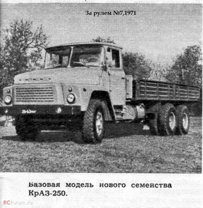
Characteristics Weight and dimensions Length 9520 mm [1] Width 2500 mm [1] Height 2695 mm [1] Wheelbase 4880 + 1400 mm Rear track 1833 mm [1] Front track 1970 mm [1] Weight 10400 kg Dynamic Max. speed 75 km/h [1] On the market Other Load capacity 12000 kg Fuel consumption 35 l Tank volume 2 × 165 l ← KrAZ-257KrAZ-250 on Wikimedia CommonsKrAZ-250
- a family of heavy trucks[2], produced by the Kremenchug Automobile Plant (KrAZ) from 1978[3] to 1992. It is a further development of the KrAZ-257[4].
Story
The development of a promising family of trucks began at the Yaroslavl Automobile Plant (YAZ) in the 1950s. Along with the transfer of truck production from Yaroslavl to Kremenchug in 1958, plans to create a new family of vehicles with the index “250” were also transferred. The most important innovation of the future cars was the new 8 and 12-cylinder engines (future YaMZ-238 and 240), cab and all-metal sides (in the version of the truck with an on-board platform). It was planned that the cab of the trucks would be all-metal, whereas the YaAZ and KrAZ trucks produced at that time had a wood-metal one (a wooden frame covered with a metal sheet). The first prototypes of the KrAZ-250, built in the early 60s, had the original “tail”, and the cabin was taken from the ZIL-130 truck. Such unification, according to the designers’ plans, made it possible to quickly develop a new generation of KrAZ trucks.
However, ZiL was unable to transfer stamps and other necessary equipment to Kremenchug, as a result of which the cabin had to be created from scratch. In the meantime, new 8-cylinder YaMZ-238 engines began to be installed on the old KrAZ models that were then being produced. Its own cabin was ready by the mid-60s. Outwardly, it resembled the future cabin of the KrAZ-250, although it differed in the design of the radiator grille, the location of the headlights on the wings rather than in the bumpers, and also had an increased glazing area, including windshields consisting of two halves.
Alas, the development of the new own cabin at KrAZ dragged on for a good two and a half five years. The plant constantly asked for equipment, which the USSR Ministry of Automotive Industry did not provide. The plan for the plant was still given to the old models 255, 256, 257, 258, which by the 70s were completely obsolete. Only in the second half of the 70s did the situation with the development of new KrAZ trucks begin to shift slightly. Since 1978, cabins of the 250th family began to be built using bypass technology, thus it became possible to put into production at least the onboard vehicles KrAZ-250 (6X4) and the army KrAZ-260 (6X6). At the same time, after rigidity tests carried out in the cabins in the 70s, many “excessive” or fragile elements had to be abandoned. Thus, the small side windows running after the doors and extending onto the building walls disappeared, and the front glazing also changed; for additional strength, it began to consist of four components. Also, as required by UNECE standards, the location of lighting devices has changed. The headlights were moved to the bumper, and the turn indicators, on the contrary, to the wings.
Despite the fact that the production of the KrAZ-250 started in 1978, it was still conditional, so the old truck models were retained in the production program for quite a long time. Following the results of the first years of operation of the KrAZ-250, the question arose about its modernization. The question of its “plumage”, its wings, was especially acute. It was difficult to make due to its original reverse slope shape, inspired by 1960s fashion. Therefore, by the beginning of the 90s, the plumage was changed to a simpler trapezoidal one.
| External images | |
| Prototype KrAZ-250 (1961) |
| External images | |
| Prototype KrAZ-250 (1967) | |
| |
The KrAZ-250 is a joint development of the Kremenchug Automobile Plant, NAMI and the Moscow Higher Technical School named after N. E. Bauman[5].
80.9% of the KrAZ-250 and KrAZ-260 parts were initially unified [6]. The front axle, discless wheels and radial tires of the KrAZ-250 are unified with the MAZ-500A[3].
In 1981, NIIATM [7] developed nylon-viscose fabric for the seats of heavy-duty KamAZ vehicles, the structure of which included up to 45% viscose threads, which are highly hygroscopic. In 1982, the fabric was introduced for seat upholstery on the KrAZ-250[8].
The production plans of the Kremenchug Automobile Plant provided for the gradual cessation of production of old models and the transition to the production of KrAZ-250 and KrAZ-260 in the second half of the 1980s[9]. In 1989, at a visiting meeting of the board of the USSR Ministry of Automotive and Agricultural Engineering, the issue of developing and mastering the production of new trucks by automobile manufacturing enterprises of the USSR was brought up for consideration. During the consideration of the issue, it was established that “ the AvtoKrAZ association is disrupting the transition to the production of KrAZ-250 and KrAZ-260 vehicles by 1990
", after which a program of necessary measures was approved aimed at mastering the production of a car in 1990 [10].
In 1992, the KrAZ-6443 truck tractor and KrAZ-6510 dump truck were created. All these models had a shortened wheelbase (4080+1400 mm) and were unified in their main units and components with the KrAZ-250.
In 1993, 7015 KrAZ-250 chassis were produced[11], the Kremenchug Automobile Plant offered production of KrAZ-250 on a separate order until 1994[12]
Other characteristics
In order to form a clearer idea of the chassis, let's look at the following indicators:
- maximum speed – 75 km/h;
- consumption per 100 km – 35 l;
- total volume of fuel tanks – 330 l;
- curb weight – 9 t;
- load capacity – 14.5 t;
- length – 9.5 m;
- height – 2.7 m;
- width – 2.5 m.
On topic: Let’s figure out which is correct: “write” or “write”
Having quite decent characteristics, a used KrAZ has a relatively low price. A truck crane, produced in 1988, can be bought for 140-160 thousand rubles.
Specifications
The all-metal three-seater cabin was created in accordance with the state standards of GOST of the USSR and complied with the CMEA and UNECE standards, equipped with a radio station[1].
The design of the KrAZ-250 onboard platform differed from the KrAZ-257 platform in metal side walls made of bent profiles and modified side locks[13].
On-board network voltage is 24 V[1].
Wheels are discless. Pneumatic tires, tube, size 11.00R—20 (300R—508)[1].
Options and modifications
- KrAZ-250
is a basic model, a flatbed truck with a payload of 14.5 tons, a maximum speed of 75 km/h and fuel consumption of 33 liters per 100 km. The body is a flatbed platform 5770 × 2450 mm with wooden folding side and rear sides. The service life before the first major overhaul was initially 200 thousand km[1][3], later it was increased to 220 thousand km[14]. - KrAZ-250V
is a truck tractor. - KrAZ-250K—chassis for mounting truck cranes produced by the Drogobych Truck Crane Plant and the Kamyshin Truck Crane Plant
- KrAZ-251
is an experimental 14-ton dump truck with rear unloading. - KrAZ-252
[9] - truck tractor.
In addition, various bodies and equipment were mounted on the KrAZ-250 chassis
In October 2014, employees of Obolon-Agro LLC (PGT Chemerovtsy, Khmelnitsky region) built an armored truck on the chassis of an airborne KrAZ-250, which was transferred to the 7th tactical aviation brigade of the Ukrainian Air Force[15].
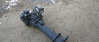
content .. 61 62 ..§ 40.
TRUCK CRANES WITH ELECTRIC DRIVE
The main load-handling element of cranes with electric drive (SMK-10, SMK-101, KS-4561A) is a hook suspension. The main type of boom equipment is a lattice boom of a reasonable length or a retractable boom. All cranes are equipped with replaceable types of boom equipment. The electric drive of cranes allows the generator to be used not only to power the crane mechanisms, but also as a source of electricity to power external 380 V AC consumers.
Rice. 133. Structure of the KS-4561 A crane: 1-way frame, 2 - rotating platform, 3, 21, 22 - winches, 4 - transformer, 5 - two-legged stand, 6 - cabin, * 7 - ropes, 8 - movable boom holder chain hoist, 9 - boom, 10 - hook suspension, 11 - base chassis, 12 - rack, 13 - power plant (generator), 14 - remote ofiopa, 15 - power cabinet, 16 - command controllers, 17 - resistance boxes, 18 - mechanism rotation, 19 — slewing support, 20 — stabilizer
Let's look at the design of the KS-4561 A crane (Fig. 133). The crane is mounted on chassis 11 of the KrAZ-257K1 (KrAZ-250) truck. The chassis contains a running frame 1 with outriggers 14, stabilizers 20 and suspension switches; power unit 13 (generator) and rack 12, on which the lattice boom 9 rests in the transport position. A slewing support device 19 is installed on the running frame, and on it is a turning platform 2. In the rear part of the turntable there are cargo 3 and jib 22 winches, and in its middle part to the right of the crane's axis of rotation there is a turning mechanism 18; Here, to the left of the crane’s axis of rotation, behind its cabin 6, an auxiliary winch 21 is located. On the right and left balconies of the turntable there is a transformer 4, command controllers 16, resistance boxes 17 and a power cabinet 15.
““ A two-legged stand 5 is installed on the turntable, the block of which, together with the movable cage 8 and the rope 7, forms a jib pulley. The boom with hook suspension 10 is installed on the racks of the rotating frame. The mechanisms on the turntable are covered with a detachable hood, which consists of several parts for ease of installation. The hood parts are secured to each other and to the rotating frame with bolts and nuts, locked with spring washers. Rubber gaskets are installed at the junctions of individual parts, as well as between the hood and frame. For ease of maintenance of the mechanisms, the hood has opening hatches, the covers of which are hinged to the corners of the frame.
The driver's cabin is located on the left side of the rotating frame on a special bracket and is attached to it with bolts and nuts. To ensure that the crane fits into the railway gauge during transportation, the upper part of the cabin is made removable. The parts of the cabin are connected with bolts and nuts, and a rubber gasket is laid in place of the connector.
In the cabin (Fig. 134, a) in front of the seat there is a control panel with alarm unit 9 for an ASON type device. On the right wall of the cabin there is an indication panel 11 and a relay unit 12 of the load limiter, a power-actuating unit 1 of the device and a tilt indicator 8.
The front, two side and rear windows provide good visibility during operation, and the fan, wiper and lamp 10 provide normal operating conditions. The cabin floor is covered with a dielectric mat, and a handrail is attached to the bottom of the front wall for ease of climbing into the cabin. The cabin is heated like car cabins, electric stoves 5 are installed inside it. To the right of the seat there are handles 2 - 4 for controlling the controllers of the auxiliary and main winch and engine fuel supply, on the left is handle 7 for controlling the controllers of the turning mechanism, in front of the seat is the pedal 6 for braking the turning mechanism.
The remote control (Fig. 134.6) is connected to the electrical equipment and control system using terminal blocks 21 and 24. After setting the universal switch to the “Normal operation” position, the controllers to the zero position and the load characteristics switch on the load limiter relay block to the corresponding characteristic handle 4 increases the rotation speed of the diesel shaft and the generator connected to it and briefly turns switch 17 (switch 30 in Fig. 60) excites the generator. Handle 4 is used to bring the diesel engine speed to operating speed (1500 rpm; frequency meter readings are 50 Hz and voltmeter readings are 400 V). Having turned on the power to the load limiter with the switch located on the relay block 12 (Fig. 134) of the limiter, press button 22 (short circuit in Fig. 60) “Start”: all crane mechanisms are prepared for operation.
To lift the load, handle 3 (Fig. 134) is moved to the “Lifting” operating position. In position I of the controller (the resistance is completely inserted into the motor rotor circuit), the lifting speed is minimal, in position V (the resistance is completely removed) - maximum. Handle 3 is moved smoothly, with a delay in each position for
2 - 3 s. When the controller is turned on, the brake receives power and releases the brake on the drum. The load is stopped by smoothly moving handle 3 to the zero position. When the controller is turned on, the brake is de-energized and brakes the drum. To further reduce the speed of lifting the load, simultaneously with moving handle 3, handle 4 reduces the speed of the vehicle engine and, consequently, the generator voltage.
To lower the load, handle 3 is moved to working positions I - V of the “Descent” sector. In position I of the controller handle, the speed of lowering the load is the highest, and in position V it is the lowest. Slow lowering of heavy loads is carried out when the cargo winch engine is operating in dynamic braking mode, for which the universal switch 37 (UP in Fig. 60) is switched to the “Slow descent” position.
To start the auxiliary winch electric motor, move handle 2 from the zero position to I - V, and to stop it, return the handle to the zero position.
The electric motor and brake of the turning mechanism are controlled by handle 7.
- To turn the crane to the right, move the handle to the “Forward” sector, to the left - to the “Back” sector. The minimum turning speed corresponds to position 1, and the maximum - to position V. The turning mechanism stops at the zero position of handle 7.
To raise, stop or lower the boom, press one of the buttons 16,
14 or 15 (K5, K7 or KB in Fig. 60), for an emergency stop of all mechanisms - button 19 “Stop” (K4 in Fig. 60).
Rice. 134. Driver’s cabin (a) and control panel (b) of the KS-4561 A crane: 1 - ASON block; control handles: 2, 3, 7 — controllers of the auxiliary and cargo winches and the turning mechanism, 4 — engine fuel supply; 5 - electric furnaces; 6 — brake pedal for the turning mechanism; 8 — tilt indicator; 9 — alarm unit ASON; 10 — lampshade; 11, 12 — panel and relay unit of the load limiter; switches: 13 - electric furnaces, 17 - generator excitation, 23, 28 - headlights, 25 - fan and windshield, 27 - lampshade, 30 - backlight; buttons: 14 - 16, 19 - "Stop", "Lowering" and "Raising" the boom, 18 - sound signal, 20 - turning off the load limiter, 22 - "Start", 36 - bypassing the limit switch; 21, 24 — terminal blocks; 26 - DC fuse; indicators: 29 - oil pressure, 31 - water temperature; 32 - ammeter; 33 — frequency meter; 34 - plate indicating the positions of the switch of relay unit 12; 35 - voltmeter; 37 - universal switch
content .. 61 62 ..