| UAZ-469B UAZ-31512 | |||||||||||||||||||||||||||||||||||||||||||||||
| Total information | |||||||||||||||||||||||||||||||||||||||||||||||
| Years of production | 1972—2005 | ||||||||||||||||||||||||||||||||||||||||||||||
| Assembly | UAZ (Ulyanovsk, USSR) UAZ (Ulyanovsk, Russia) Ganja Automobile Plant (Ganja, Azerbaijan) Thanh Xuan Industry Automobile-Motorbike Co. (Hanoi, Vietnam) KrAZ (Kremenchug, Ukraine) (Laos) | ||||||||||||||||||||||||||||||||||||||||||||||
| Class | off-road car | ||||||||||||||||||||||||||||||||||||||||||||||
| Design | |||||||||||||||||||||||||||||||||||||||||||||||
| Body type | 4/5-door station wagon 4-door phaeton station wagon | ||||||||||||||||||||||||||||||||||||||||||||||
| Platform | UAZ-469 | ||||||||||||||||||||||||||||||||||||||||||||||
| Layout | front-engine, all-wheel drive | ||||||||||||||||||||||||||||||||||||||||||||||
| Engine | |||||||||||||||||||||||||||||||||||||||||||||||
| |||||||||||||||||||||||||||||||||||||||||||||||
| ZM3-4021.10 | |||||||||||||||||||||||||||||||||||||||||||||||
| Manufacturer: | Zavolzhsky Motor Plant | ||||||||||||||||||||||||||||||||||||||||||||||
| Brand: | ZM3-4021.10 | ||||||||||||||||||||||||||||||||||||||||||||||
| Type: | Petrol | ||||||||||||||||||||||||||||||||||||||||||||||
| Volume: | 2,450 cm3 | ||||||||||||||||||||||||||||||||||||||||||||||
| Maximum power: | 95 l. With. (69.8 kW kW), at 2,400 - 2,600 rpm | ||||||||||||||||||||||||||||||||||||||||||||||
| Maximum torque: | 166 Nm | ||||||||||||||||||||||||||||||||||||||||||||||
| Configuration: | in-line, 4-cylinder. | ||||||||||||||||||||||||||||||||||||||||||||||
| Cylinders: | 4 | ||||||||||||||||||||||||||||||||||||||||||||||
| Valves: | 8 | ||||||||||||||||||||||||||||||||||||||||||||||
| Max. speed: | 120 km/h | ||||||||||||||||||||||||||||||||||||||||||||||
| Fuel consumption combined cycle: | 15.5 l/100 km | ||||||||||||||||||||||||||||||||||||||||||||||
| Environmental standards: | Euro 0 | ||||||||||||||||||||||||||||||||||||||||||||||
| Cylinder diameter: | 92 mm | ||||||||||||||||||||||||||||||||||||||||||||||
| Piston stroke: | 92 mm | ||||||||||||||||||||||||||||||||||||||||||||||
| Compression ratio: | 6,7 | ||||||||||||||||||||||||||||||||||||||||||||||
| Supply system: | carburetor | ||||||||||||||||||||||||||||||||||||||||||||||
| Cooling: | Forced, water | ||||||||||||||||||||||||||||||||||||||||||||||
| Valve mechanism: | Nizhnevalny | ||||||||||||||||||||||||||||||||||||||||||||||
| Cylinder block material: | Aluminum | ||||||||||||||||||||||||||||||||||||||||||||||
| Cylinder head material: | Aluminum | ||||||||||||||||||||||||||||||||||||||||||||||
| Cylinder operating order: | 1-2-4-3 | ||||||||||||||||||||||||||||||||||||||||||||||
| Recommended fuel: | A-80, You can use A-92, A-95 | ||||||||||||||||||||||||||||||||||||||||||||||
UAZ-31514 →UAZ-469B UAZ-31512 on Wikimedia Commons
UAZ-469B
- an all-wheel drive off-road passenger vehicle for use on roads of all categories, as well as over rough terrain.
The UAZ-469B car is a “civilian” version of the UAZ-469 model - without a starting heater, drive axles with a single-stage main gear without final drives (ground clearance 220 mm), made on the basis of the drive axles of the GAZ-69 car, [1] contact ( on early models) or a contactless electronic ignition system. The driveshafts are slightly longer compared to the shafts of the UAZ-469. The car is open with a phaeton-type body, with a canvas awning (cars with metal or fiberglass roofs are formerly tarpaulin, the hard top was installed separately or as an additional equipment), 2.4 liter engine, 4-speed gearbox.
The UAZ-469B was serially produced by the Ulyanovsk Automobile Plant from 1972 to 1985, after which, in accordance with the 1966 industry system, it received the four-digit number 31512 (number 3151 was given to the model with UAZ-469 gear axles).
UAZ-31512
produced from 1985 to 2005.
Options and modifications
- A modification of the UAZ-31512-UMM with a metal insulated five-door body and installed additional special equipment was produced as a police patrol car [2].
UAZ "Scorpion"
- In 2002, at the INTERPOLITEX-2002 arms exhibition, the Scorpion attack vehicle, created on the basis of the UAZ-3151, was presented: with a new 170 hp engine. s., power steering, removable armored panels, bulletproof glass, bulletproof tires and a telescopic turret stand (on which a machine gun or automatic grenade launcher can be mounted). The weight of the vehicle increased to 2,880 kg[3]
Schematic features
UAZ 390345, 315314 and analogues in the general wiring have high-quality and reliable components. These are the following types of alarms:
- parking brake;
- level of brake fluid used;
- turning on headlights for high beam;
- switching on for turn signals;
- cooler overheating;
- emergency oil pressure;
- coolant temperature;
- oil pressure and fuel level readings.
All of them are distinguished by a high level of reliability, quality, and durability of use. The wiring includes a microswitch for the carburetor (for model 390994, an injector and the necessary sensors for it), an EPHH valve of the electromagnetic type. The following sections of the circuit are provided for lighting:
- central light switch;
- interior lamp;
- right, left steering column switch;
- fuel level sensors, rear light;
- fog rear lights;
- license plate light;
- reversing lights.
Separately, the electrical circuit of the UAZ 390994 (315314) has such points as power for the cigarette lighter, trailer socket, bimetallic (that is, thermal) fuse. It must be remembered that such wiring for the UAZ 390945 trailer socket is not available on all models, but only on some. If necessary, you can connect additional equipment.
Engine compartment
For many years, the main power unit of the UAZ 469 was the in-line 4-cylinder UMZ-451MI carburetor type. The engine capacity was 2445 cc. cm, power – 75 hp.
With this engine produced by the Ufa Motor Plant, the UAZ 469 lasted on the factory assembly line until 1985.
It was distinguished by a simple single-wire 12-volt ignition circuit, which consisted of (according to the numbering):
- rechargeable battery (AB);
- mechanical ground switch;
- electronic battery charge voltage regulator;
- alternator;
- ammeter on the instrument panel;
- ignition switch (switch);
- ignition breaker contact group;
- directly to the ignition distributor (distributor);
- capacitor built into the distributor;
- ebonite distributor cover with leads for high-voltage wires;
- ignition distributor slider;
- spark plugs;
- high voltage wires from the ignition coil;
- additional coil resistance;
- starter relay;
- directly to the high-voltage ignition coil;
- electric starter.
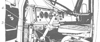
For reference: on the black and white diagram of the ignition system shown, the letters indicate the wiring on the UAZ 469 according to the color of the wires. K - red, O - orange, G - blue; F – purple and Ch – black (according to the capital letters of the names).
New modifications of the legendary SUV received more modern engines and a modified electrical circuit.
In particular, the UAZ Patriot wiring diagram includes:
- electronic fuel injection system;
- contactless ignition system;
- climate control system inside the car;
- alarm system, etc.
Electrical wiring components for UAZ 469, UAZ 390945 and other models
The electrical circuit of the UAZ 3151 4 includes 69 positions; it is possible to additionally connect special fog lights, but the installation of a switch type 343.01.03 is required. It will be mounted directly on the dashboard in a convenient location. The general wiring diagram of a machine includes an extensive list of different devices.
This is a front light, headlights that are easy to replace if necessary. An audio signal is also connected to the general system. Further, the UAZ wiring diagram includes a special fuse and additional resistance. The circuit has a connection to the side direction indicators, and a switch for the heater is located right there.
The wiring supplies the generator, there are connection points for the light that illuminates the engine compartment, and outputs for the heater fan motor. Modern UAZ electrical wiring includes spark plugs powered by it. A relay is installed for indicators; it is used to ensure the operation of emergency and turn signals.
The electrical circuit has outputs to a coil, a starter relay, there is a special sensor-distributor, and a switch. In one area there are the following points: turn off the masses, hazard warning lights, battery, electric washer. There is a separate connection for the fuse box and the following sensors:
- emergency pressure for oil;
- fuel readings;
- for oil pressure indicator;
- overheating of used coolers;
- temperatures of the coolers used;
- determining the brake fluid level.
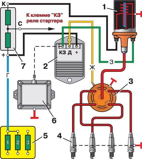
1.Low voltage ignition coil; 2.Transistor electronic switch; 3. Sensor-distributor (distributor); 4.Electric spark plugs; 5.Fuse block; 6.Emergency breaker; 7.Additional electrical resistance.
The electrical diagram includes connection points for the starter, speedometer, windshield wiper and relay for it, EPH unit, voltmeter. There are the following components:
- relay for car headlights;
- sockets used to power portable lamps;
- parking brake switches, braking systems.
For electrical equipment of UAZ 31512(14) or UAZ 390945, the following switches are installed:
- for brake signal;
- for parking brake;
- alarm;
- interior light lamps;
- sound signal;
- rear fog lamp;
- ignition;
- reverse lights.
The electrical circuit of the UAZ-469 combines all the devices and instruments used in the car. If malfunctions occur in the system, full operation of the car can cause difficulties for the car owner, so all breakdowns must be promptly repaired. You can learn more about malfunctions, as well as wiring prevention, from this material.
Electrical circuit diagrams for UAZ-469, 31512, 31514, 31519
Multithumb found errors on this page: There was a problem loading image https://spike.su/images/clip_image001_d84c30cb-2761-4fb4-864c-f53482efcef1.jpg There was a problem loading image https://spike.su/images/ clip_image001_d84c30cb-2761-4fb4-864c-f53482efcef1.jpg There was a problem loading image https://spike.su/images/clip_image002_537c1934-ac88-45b7-9a77-92d3d6198285.jpg There was a problem loading image https://spike. su/images/clip_image002_537c1934-ac88-45b7-9a77-92d3d6198285.jpg There was a problem loading image https://spike.su/images/clip_image0014_265e7aad-6266-4e3a-a4a1-26563d88ace5.jpg There was a problem loading image https : //spike.su/images/clip_image0014_265e7aad-6266-4e3a-a4a1-26563d88ace5.jpg
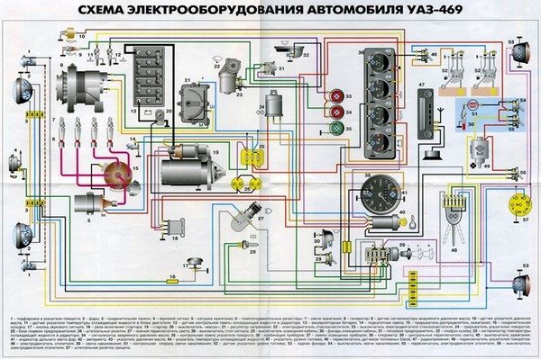
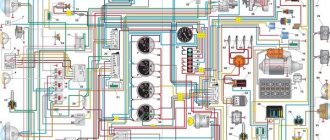
Electrical diagram of UAZ-469
1 — front lamp; 2 - headlight; 3 — sound signal; 4 — connecting block; 5 — side direction indicator; 6 — additional resistance; 7 — heater switch; 8 — heater fan electric motor; 9 — engine compartment lighting; 10 - generator; 11 — direction indicator relay; 12 — spark plugs; 13 — ignition coil; 14 — starter relay; 15 — starter; 16 — ignition distributor sensor; 17 - switch; 18 — battery; 19 — electric windshield washer; 20 — windshield wiper; 21 — “mass” switch; 22 — portable lamp socket; 23 — emergency vibrator; 24 - fuse block; 25 — oil pressure indicator sensor; 26 — coolant temperature sensor; 27 — coolant overheat warning lamp sensor; 28 — emergency oil pressure warning lamp sensor; 29 — switch for the emergency signal lamp of the hydraulic brake drive;
30 — parking brake warning lamp switch; 31 — brake signal switch; 32 — voltage regulator*; 33 — foot light switch; 34 — parking brake warning lamp; 35 — signal lamp of direction indicators; 36 — warning lamp for emergency condition of the hydraulic brake drive; 37 — horn switch; 38 — carburetor microswitch; 39 — electromagnetic valve of the EPHH system; 40 — block of the EPHH system; 41 — windshield wiper and washer switch; 42 — speedometer; 43 — warning lamp for emergency oil pressure; 44 - warning lamp for coolant overheating; 45 - central light switch; 46 — alarm switch; 47 — fuel level indicator; 48 — coolant temperature indicator; 49 — oil pressure indicator; 50 - ammeter; 51 — signal lamp for high beam headlights; 52 — interior lamp; 53 — interior lamp switch; 54 — direction indicator switch; 55 — fuel level indicator sensor; 56 - thermal (bimetallic) fuse; 57 — fuel tank sensor switch; 58 — ignition switch; 59 — reverse light switch; 60 — rear light; 61 — trailer socket**; 62 — reversing light; 63 — license plate light. * On vehicles with generator types 665.3701, 161.3771, G700A.30 and 957.3701, an external voltage regulator is not installed. ** Installed on some vehicles. Note. On cars of recent years of production, the ammeter is replaced by a voltmeter, the brake warning light switch is replaced by a low brake fluid level sensor, and the high beam headlight warning light is placed on the dashboard.
https://www.drive2.ru/l/1606894/, https://myauto.jofo.ru/430624.html
next article:
Installation of VAZ-classic electric fans on UAZ 31512
Connection: mechanics I have long wanted to install electric fans and finally got around to it. Two were purchased
Rating 0.00 [0 Vote(s)]
Electrical equipment UAZ 3151
/ UAZ/ uaz-3151/ Electrical equipment/ Electrical equipment
ACCUMULATOR BATTERY
POSSIBLE BATTERY MALFUNCTIONS, THEIR CAUSES AND REMEDY METHODS
GENERATOR
POSSIBLE GENERATOR MALFUNCTIONS, THEIR CAUSES AND REMEDY METHODS
POSSIBLE MALFUNCTIONS OF THE VOLTAGE REGULATOR, THEIR CAUSES AND REMEDY METHODS
STARTER
POSSIBLE MALFUNCTIONS OF THE STARTER, THEIR CAUSES AND REMEDY METHODS
CONTACTLESS IGNITION SYSTEM
POSSIBLE MALFUNCTIONS OF THE IGNITION SYSTEM, THEIR CAUSES AND REMEDY METHODS
LIGHTING AND SIGNALING DEVICES
POSSIBLE MALFUNCTIONS OF LIGHTING AND SIGNALING DEVICES, THEIR CAUSES AND REMEDY METHODS
CONTROL DEVICES
POSSIBLE MALFUNCTIONS OF CONTROL DEVICES, THEIR CAUSES AND REMEDY METHODS
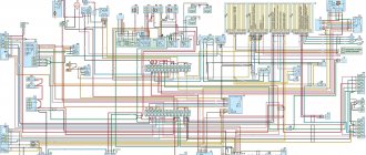
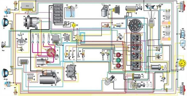
| Rice. 7.1. Electrical diagram of vehicles of the UAZ-31512 family (except UAZ-3153): 1 – front lamp; 2 – headlight; 3 – fog lamp; 4 – sound signal; 5 – generator; 6 – engine compartment lamp; 7 – coolant temperature indicator sensor in the cylinder block; 8 – sensor for warning light of emergency overheating of coolant in the radiator; 9 – signal lamp sensor for emergency condition of the hydraulic brake system; 10 – oil pressure indicator sensor; 11 – sensor for emergency oil pressure warning lamp; 12 – EPHH control microswitch; 13 – spark plugs; 14 – sensor-distributor; 15 – electric motor for windshield washer; 16 – electromagnetic valve EPHH; 17 – carburetor solenoid valve; 18 – ignition coil; 19 – battery; 20 – ground switch; 21 – starter; 22 – additional resistance; 23 – side turn signal repeater; 24 – fog lamp switch; 25 – cigarette lighter; 26 – cigarette lighter fuse; 27 – emergency vibrator; 28 – transistor switch; 29 – electronic control unit EPHH; 30 – windshield wiper motor; 31 – starter relay; 32 – fuse block; 33 – brake signal switch; 34 – direction indicator switch; 35 – alarm switch; 36 – turn signal switch; 37 – plug socket; 38 – body light switch; 39 – body lighting lamp; 40 – wiper and washer motor switch; 41 – heater fan electric motor; 42 – heater fan motor switch; 43 – heater resistor; 44 – heater motor fuse; 45 – ignition switch; 46 – thermal fuse; 47 – central light switch; 48 – foot light switch; 49 – voltmeter; 50 – oil pressure indicator; 51 – warning lamp for emergency oil pressure; 52 – coolant temperature indicator in the engine cylinder block; 53 – warning lamp for emergency overheating of the coolant in the radiator; 54 – fuel level indicator; 55 – signal lamp of direction indicators; 56 – warning lamp for emergency condition of the hydraulic drive of the brake system; 57 – signal lamp for turning on the parking brake system; 58 – sound signal button; 59 – signal lamp for turning on the high beam headlights; 60 – speedometer; 61 – fog lamp switch; 62 – parking brake system warning lamp switch; 63 – reverse light switch; 64 – fuel level indicator sensor in the right tank; 65 – fuel level sensor switch; 66 – fuel level indicator sensor in the left tank; 67 – rear lamp; 68 – license plate light; 69 – reversing lamp; 70 – trailer socket; 71 – rear fog lamp |
| Rice. 7.2. Electrical diagram of the UAZ-3153 car: 1 – front lamp; 2 – headlight; 3 – fog lamp; 4 – sound signal; 5 – fog lamp; 6 – headlight; 7 – front lamp; 8 – generator; 9 – emergency oil pressure sensor; 10 – oil pressure sensor; 11 – coolant temperature sensor; 12 – emergency coolant temperature sensor; 13, 14, 15, 16 – spark plug; 17 – sensor-distributor; 18 – starter; 19 – electric washer; 20 – battery; 21 – ground switch; 22 – microswitch; 23 – electromagnetic valve EPHH; 24 – carburetor solenoid valve; 25 – brake system malfunction warning lamp switch; 26 – ignition coil; 27 – starter relay; 28 – engine compartment lamp; 29 – fuse block; 30 – additional resistance; 31 – side repeater; 32, 33 – headlight switching relay; 34 – fog lamp relay; 35 – fog lamp fuse; 36 – EPHH block; 37 – brake light switch; 38 – side repeater; 39 – transistor switch; 40 – emergency vibrator; 41 – windshield wiper; 42 – heater electric motor; 43 – heater resistance; 44 – windshield wiper breaker; 45 – instrument panel; 46 – speedometer; 47 – direction indicator and hazard warning relay; 48 – plug socket; 49 – control lamp for turning on the high beam headlights; 50 – indicator lamp for direction indicators; 51 – indicator lamp for turning on the parking brake; 52 – warning lamp for brake system malfunction; 53 – warning lamp for emergency oil pressure; 54 – warning lamp for emergency coolant temperature; 55 – thermal fuse 20 A; 56 – interior lamp switch; 57 – ignition switch; 58 – ignition switch relay; 59 – rheostat for instrument lighting; 60 – light signaling switch; 61 – sound signal button; 62 – wiper switch; 63 – reverse light switch; 64 – fuel level sensor switch; 65 – parking brake warning lamp switch; 66 – rear fog lamp switch; 67 – external lighting switch; 68 – heater switch; 69 – alarm switch; 70 – cigarette lighter fuse; 71 – fog lamp switch; 72 – fuel level sensor; 73, 74 – interior lamps; 75 – fuel level sensor; 76 – cigarette lighter; 77 – rear lamp; 78 – reversing lamp; 79, 80 – license plate lights; 81 – rear fog lamp; 82 – rear lamp |
| Rice. 7.3. Electrical diagram of UAZ-3741, -3909, -3962, -2206 cars: 1 – front lamp; 2 – headlight; 3 – special sign lamp (only for UAZ-3962); 4 – heater fan electric motor (only for UAZ-3962, UAZ-2206); 5 – signal lamp sensor for emergency condition of the hydraulic brake drive; 6 – sound signal; 7 – side turn signal repeater; 8 – turning headlight (only for UAZ-3962); 9 – turning headlight switch; 10 – cabin lighting; 11 – signal lamp for turning on the parking brake system; 12 – switch for the parking brake system warning lamp; 13 – windshield wiper motor; 14 – switch for the electric motor of the windshield wiper and washer; 15 – speedometer; 16 – signal lamp for turning on the high beam headlights; 17 – voltmeter; 18 – oil pressure indicator; 19 – warning lamp for emergency oil pressure; 20 – coolant temperature indicator in the engine cylinder block; 21 – warning lamp for emergency overheating of the coolant in the radiator; 22 – fuel level indicator; 23 – washer motor; 24 – alarm switch; 25 – signal lamp for direction indicators; 26 – emergency signal lamp for the hydraulic brake system; 27 – ignition switch; 28 – central light switch; 29 – thermal fuse; 30 – heater resistance; 31 – heater fan motor switch; 32 – headlight switch; 33 – rear fog lamp switch; 34 – fuse block; 35 – plug socket; 36 – unbalance solenoid valve; 37 – direction indicator switch; 38 – sound signal button; 39 – sensor for emergency oil pressure warning lamp; 40 – warning lamp sensor for emergency overheating of the coolant in the radiator; 41 – oil pressure indicator sensor; 42 – coolant temperature indicator sensor in the cylinder block; 43 – turn signal switch; 44 – heater fuse (only for UAZ-3962, UAZ-2206); 45 – heater fan electric motor switch (only for UAZ-3962, UAZ-2206); 46 – resistance of the heater fan electric motor switch (only for UAZ-3962, UAZ-2206); 47 – heater fan electric motor (only for UAZ-3962, UAZ-2206); 48 – generator; 49 – spark plug; 50 – sensor-distributor; 51 – ignition coil; 52 – ground switch; 53 – rechargeable battery; 54 – lamp switch; 55 – plug socket (only for UAZ-3962, UAZ-2206); 56 – lampshade; 56* – lampshade (only for UAZ-3962, UAZ-2206); 57 – transistor switch; 58 – emergency vibrator; 59 – electronic carburetor control unit; 60 – microswitch; 61 – additional resistance; 62 – additional starter relay; 63 – solenoid valve; 64 – starter; 65 – fuel level indicator sensor in the tank; 66 – brake signal switch; 67 – reverse light switch; 68 – rear lamp; 69 – rear fog lamp; 70 – license plate light; 71 – reversing lamp; 72 – trailer socket |
| Rice. 7.4. Electrical diagram of UAZ-3303 vehicles: 1 – front lamp; 2 – headlight; 3 – heater fan electric motor; 4 – sensor for warning lamp of emergency condition of hydraulic brake drive; 5 – sound signal; 6 – washer motor; 7 – cabin light switch; 8 – cabin lighting; 9 – warning lamp for turning on the parking brake system; 10 – switch for the parking brake system warning lamp; 11 – windshield wiper motor; 12 – switch for the electric motor of the windshield wiper and washer; 13 – speedometer; 14 – signal lamp for turning on the high beam headlights; 15 – voltmeter; 16 – oil pressure indicator; 17 – warning lamp for emergency oil pressure; 18 – coolant temperature indicator in the engine cylinder block; 19 – warning lamp for emergency overheating of the coolant in the radiator; 20 – fuel level indicator; 21 – alarm switch; 22 – cigarette lighter; 23 – cigarette lighter fuse; 24 – signal lamp for direction indicators; 25 – emergency signal lamp for the hydraulic brake system; 26 – ignition switch; 27 – central light switch; 28 – thermal fuse; 29 – heater resistance; 30 – heater fan motor switch; 31 – headlight switch; 32 – rear fog lamp switch; 33 – fuse block; 34 – plug socket; 35 – unbalance solenoid valve; 36 – direction indicator switch; 37 – sound signal button; 38 – sensor for emergency oil pressure warning lamp; 39 – warning lamp sensor for emergency overheating of the coolant in the radiator; 40 – oil pressure indicator sensor; 41 – coolant temperature indicator sensor in the cylinder block; 42 – turn signal switch; 43 – heater fuse; 44 – heater fan motor switch; 45 – resistance of the heater fan motor switch; 46 – heater fan electric motor; 47 – generator; 48 – spark plug; 49 – sensor-distributor; 50 – ignition coil; 51 – ground switch; 52 – rechargeable battery; 53 – fuel level indicator sensor in the tank; 54 – transistor switch; 55 – emergency vibrator; 56 – electronic carburetor control unit; 57 – microswitch; 58 – additional resistance; 59 – additional starter relay; 60 – solenoid valve; 61 – starter; 62 – fuel level indicator sensor in the tank; 63 – fuel tank sensor switch; 64 – brake signal switch; 65 – reverse light switch; 66 – rear lamp; 67 – rear fog lamp; 68 – license plate light; 69 – reversing lamp |
| Rice. 7.5. Electrical diagram of a UAZ-33036 car without multifunctional steering column switches: 1, 6 – front lights; 2, 5 – headlights; 3, 4 – fog lights; 7 – switch for warning lamp for brake system malfunction; 8 – sound signal; 9 – windshield wiper; 10 – brake light switch; 11 – direction indicator switch; 12 – electric washer; 13 – heater resistance; 14 – fog lamp relay; 15, 16 – headlight switching relay; 17 – fuse for fog lights 10 A; 18 – relay for direction indicators and hazard warning lights; 19 – headlight switch; 20 – heater electric motor; 21 – cigarette lighter; 22 – cigarette lighter fuse 16 A; 23 – windshield wiper switch; 24 – sound signal button; 25 – cabin light switch; 26 – thermal fuse 20 A; 27 – fuse block; 28 – plug socket; 29 – cabin heater switch; 30 – external lighting switch; 31 – rheostat for instrument lighting; 32 – speedometer; 33 – voltage indicator; 34 – oil pressure indicator; 35 – coolant temperature indicator; 36 – fuel level indicator; 37 – rear fog lamp switch; 38 – control lamp for high beam headlights; 39 – indicator lamp for direction indicators; 40 – indicator lamp for turning on the parking brake; 41 – warning lamp for brake system malfunction; 42 – warning lamp for emergency oil pressure; 43 – warning lamp for emergency coolant temperature; 44 – ignition switch; 45 – control unit EPPH; 46 – fog lamp switch; 47 – alarm switch; 48 – cabin lighting; 49 – generator; 50 – emergency oil pressure sensor; 51 – oil pressure sensor; 52 – coolant temperature sensor; 53 – emergency coolant temperature sensor; 54 – transistor switch; 55 – emergency vibrator; 56 – parking brake warning lamp switch; 57 – additional resistance; 58 – starter relay; 59 – electromagnetic valve EPPH; 60 – unbalance solenoid valve; 61 – microswitch; 62, 63, 64, 65 – spark plugs; 66 – sensor-distributor; 67 – ignition coil; 68 – side repeater; 69 – fuel level sensor switch; 70 – starter; 71 – battery; 72 – ground switch; 73 – reverse light switch; 74 – side repeater; 75, 76 – fuel level sensors; 77, 82 – rear lights; 78, 79 – license plate lights; 80 – rear fog lamp; 81 – reversing lamp |
| Rice. 7.6. Electrical diagram of a UAZ-33036 car with multifunctional steering column switches: 1 – front lamp; 2 – headlight; 3, 4 – fog lights; 5 – headlight; 6 – front lamp; 7 – switch for warning lamp for brake system malfunction; 8 – sound signal; 9 – windshield wiper; 10 – brake light switch; 11 – windshield wiper breaker; 12 – electric washer; 13 – heater resistance; 14 – fog lamp relay; 15, 16 – headlight switching relay; 17 – fuse for fog lights 10 A; 18 – relay for direction indicators and hazard warning lights; 19 – hours; 20 – heater electric motor; 21 – cigarette lighter; 22 – cigarette lighter fuse 16 A; 23 – switch for direction indicators and light signaling; 24 – sound signal button; 25 – wiper switch; 26 – thermal fuse 20 A; 27 – fuse block; 28 – plug socket; 29 – cabin heater switch; 30 – external lighting switch; 31 – rheostat for instrument lighting; 32 – cabin light switch; 33 – speedometer; 34 – voltage indicator; 35 – oil pressure indicator; 36 – coolant temperature indicator; 37 – fuel level indicator; 38 – rear fog lamp switch; 39 – control lamp for high beam headlights; 40 – indicator lamp for direction indicators; 41 – indicator lamp for turning on the parking brake; 42 – warning lamp for brake system malfunction; 43 – warning lamp for emergency oil pressure; 44 – warning lamp for emergency coolant temperature; 45 – ignition switch; 46 – ignition switch relay; 47 – control unit EPPH; 48 – fog lamp switch; 49 – alarm switch; 50 – cabin lighting; 51 – generator; 52 – emergency oil pressure sensor; 53 – oil pressure sensor; 54 – coolant temperature sensor; 55 – emergency coolant temperature sensor; 56 – transistor switch; 57 – emergency vibrator; 58 – parking brake warning lamp switch; 59 – additional resistance; 60 – starter relay; 61 – electromagnetic valve EPPH; 62 – unbalance solenoid valve; 63 – microswitch; 64, 65, 66, 67 – spark plugs; 68 – sensor-distributor; 69 – ignition coil; 70 – side repeater; 71 – fuel level sensor switch; 72 – starter; 73 – battery; 74 – ground switch; 75 – reverse light switch; 76 – side repeater; 77, 78 – fuel level sensors; 79, 84 – rear lights; 80, 81 – license plate light; 82 – rear fog lamp; 83 – reversing lamp |
| Rice. 7.7. Electrical diagram of a UAZ-39094 car with multifunctional steering column switches: 1 – front lamp; 2 – headlight; 3, 4 – fog lights; 5 – headlight; 6 – front lamp; 7 – switch for warning lamp for brake system malfunction; 8 – sound signal; 9 – windshield wiper; 10 – brake light switch; 11 – windshield wiper breaker; 12 – electric washer; 13 – heater resistance; 14 – fog lamp relay; 15, 16 – headlight switching relay; 17 – fuse for fog lights 10 A; 18 – relay for direction indicators and hazard warning lights; 19 – hours; 20 – heater electric motor; 21 – cigarette lighter; 22 – cigarette lighter fuse 16 A; 23 – switch for direction indicators and light signaling; 24 – sound signal button; 25 – wiper switch; 26 – thermal fuse 20 A; 27 – fuse block; 28 – plug socket; 29 – cabin heater switch; 30 – external lighting switch; 31 – rheostat for instrument lighting; 32 – lamp lamp switch; 33 – speedometer; 34 – voltage indicator; 35 – oil pressure indicator; 36 – coolant temperature indicator; 37 – fuel level indicator; 38 – rear fog lamp switch; 39 – control lamp for high beam headlights; 40 – indicator lamp for direction indicators; 41 – indicator lamp for turning on the parking brake; 42 – warning lamp for brake system malfunction; 43 – warning lamp for emergency oil pressure; 44 – warning lamp for emergency coolant temperature; 45 – ignition switch; 46 – ignition switch relay; 47 – control unit EPPH; 48 – fog lamp switch; 49 – alarm switch; 50 – cabin lighting; 51 – generator; 52 – emergency oil pressure sensor; 53 – oil pressure sensor; 54 – coolant temperature sensor; 55 – emergency coolant temperature sensor; 56 – transistor switch; 57 – emergency vibrator; 58 – parking brake warning lamp switch; 59 – additional resistance; 60 – starter relay; 61 – electromagnetic valve EPPH; 62 – unbalance solenoid valve; 63 – microswitch; 64, 65, 66, 67 – spark plugs; 68 – sensor-distributor; 69 – ignition coil; 70 – side repeater; 71 – interior lamp; 72 – starter; 73 – battery; 74 – ground switch; 75 – reverse light switch; 76 – side repeater; 77 – fuel level sensor; 78, 83 – rear lights; 79, 80 – license plate lights; 81 – rear fog lamp; 82 – reversing lamp |
| Rice. 7.8. Electrical diagram of a UAZ-39095 car with multifunctional steering column switches: 1 – front lamp; 2 – headlight; 3, 4 – fog lights; 5 – headlight; 6 – front lamp; 7 – switch for warning lamp for brake system malfunction; 8 – sound signal; 9 – windshield wiper; 10 – brake light switch; 11 – windshield wiper breaker; 12 – electric washer; 13 – heater resistance; 14 – fog lamp relay; 15, 16 – headlight switching relay; 17 – fuse for fog lights 10 A; 18 – relay for direction indicators and hazard warning lights; 19 – hours; 20 – heater electric motor; 21 – cigarette lighter; 22 – cigarette lighter fuse 16 A; 23 – switch for direction indicators and light signaling; 24 – sound signal button; 25 – wiper switch; 26 – thermal fuse 20 A; 27 – fuse block; 28 – plug socket; 29 – cabin heater switch; 30 – external lighting switch; 31 – rheostat for instrument lighting; 32 – cabin light switch; 33 – speedometer; 34 – voltage indicator; 35 – oil pressure indicator; 36 – coolant temperature indicator; 37 – fuel level indicator; 38 – rear fog lamp switch; 39 – control lamp for high beam headlights; 40 – indicator lamp for direction indicators; 41 – indicator lamp for turning on the parking brake; 42 – warning lamp for brake system malfunction; 43 – warning lamp for emergency oil pressure; 44 – warning lamp for emergency coolant temperature; 45 – ignition switch; 46 – ignition switch relay; 47 – control unit EPPH; 48 – fog lamp switch; 49 – alarm switch; 50 – cabin lighting; 51 – generator; 52 – emergency oil pressure sensor; 53 – oil pressure sensor; 54 – coolant temperature sensor; 55 – emergency coolant temperature sensor; 56 – transistor switch; 57 – emergency vibrator; 58 – parking brake warning lamp switch; 59 – additional resistance; 60 – starter relay; 61 – electromagnetic valve EPPH; 62 – unbalance solenoid valve; 63 – microswitch; 64, 65, 66, 67 – spark plugs; 68 – sensor-distributor; 69 – ignition coil; 70 – side repeater; 71 – fuel level sensor switch; 72 – starter; 73 – battery; 74 – ground switch; 75 – reverse light switch; 76 – side repeater; 77, 78 – fuel level sensors; 79, 84 – rear lights; 80, 81 – license plate lights; 82 – rear fog lamp; 83 – reversing lamp |
| Rice. 7.9. Electrical diagram of a UAZ-39095 car without multifunctional steering column switches: 1, 6 – front lights; 2, 5 – headlights; 3, 4 – fog lights; 7 – switch for warning lamp for brake system malfunction; 8 – sound signal; 9 – windshield wiper; 10 – brake light switch; 11 – direction indicator switch; 12 – electric washer; 13 – heater resistance; 14 – fog lamp relay; 15, 16 – headlight switching relay; 17 – fuse for fog lights 10 A; 18 – relay for direction indicators and hazard warning lights; 19 – headlight switch; 20 – heater electric motor; 21 – cigarette lighter; 22 – cigarette lighter fuse 16 A; 23 – wiper switch; 24 – sound signal button; 25 – cabin light switch; 26 – thermal fuse 20 A; 27 – fuse block; 28 – plug socket; 29 – cabin heater switch; 30 – external lighting switch; 31 – rheostat for instrument lighting; 32 – speedometer; 33 – voltage indicator; 34 – oil pressure indicator; 35 – coolant temperature indicator; 36 – fuel level indicator; 37 – rear fog lamp switch; 38 – control lamp for high beam headlights; 39 – indicator lamp for direction indicators; 40 – indicator lamp for turning on the parking brake; 41 – warning lamp for brake system malfunction; 42 – warning lamp for emergency oil pressure; 43 – warning lamp for emergency coolant temperature; 44 – ignition switch; 45 – control unit EPPH; 46 – fog lamp switch; 47 – alarm switch; 48 – cabin lighting; 49 – generator; 50 – emergency oil pressure sensor; 51 – oil pressure sensor; 52 – coolant temperature sensor; 53 – emergency coolant temperature sensor; 54 – transistor switch; 55 – emergency vibrator; 56 – parking brake warning lamp switch; 57 – additional resistance; 58 – starter relay; 59 – electromagnetic valve EPPH; 60 – unbalance solenoid valve; 61 – microswitch; 62, 63, 64, 65 – spark plugs; 66 – sensor-distributor; 67 – ignition coil; 68 – side repeater; 69 – fuel level sensor switch; 70 – starter; 71 – battery; 72 – ground switch; 73 – reverse light switch; 74 – side repeater; 75, 76 – fuel level sensors; 77, 82 – rear lights; 78, 79 – license plate lights; 80 – rear fog lamp; 81 – reversing lamp |
The electrical equipment of cars is made according to a single-wire circuit. The negative terminal of the battery is connected to the vehicle ground. Rated voltage 12 V. Electrical circuits for cars are shown in Fig. 7.1, 7.2, 7.3, 7.4, 7.5, 7.6, 7.7, 7.8, 7.9.
Comments
No comments yet
Leave a comment Cancel reply
Historical reference
Traditionally, the UAZ 469 was produced in two versions:
- Cargo-passenger version - 7 seats and 100 kg of luggage;
- Commander version - 2 seats for passengers and 600 kg of luggage.
For reference: regardless of the version, the UAZ 469 can tow a trailer with a total weight of 850 kg.
Industry standard 1945
According to the old vehicle classification system, in force since 1945, the UAZ 469 was produced under this name, using an alphanumeric name:
- The letter abbreviation UAZ stood for Ulyanovsk Automobile Plant;
- 469 is a serial factory index assigned by the enterprise itself to its models and developments.
For reference: according to the industry standard of 1945, each automobile plant was assigned a specific numbering. For MZMA, which produced Moskvich 408 and 412, these are numbers from 400 to 449, for the Ulyanovsk Automobile Plant these are numbers from 450 to 484, etc.
1966 Industry Standard
Although at the time of the release of the UAZ 469 (1972) a new industry classification system was adopted (industry standard OH 025270-66), the car plant continued to use the name according to the old standard.
However, in 1985, the automaker was forced to change its name in accordance with current requirements:
- the car was assigned a four-digit number - 3151;
- According to the new system, the car can be called in the documentation as UAZ 3151.
For reference: industry standard OH 025270-66 prescribes determining the type of vehicle by engine displacement, length and weight. The first digit indicates the class of the car, the second – the type (truck or passenger car), the third and fourth – the factory model index.
The car plant named all further modifications and new models in accordance with current standards. In particular, the UAZ Patriot, which appeared in 2005, according to the industry classification, received the “correct” designation - UAZ-3163. For greater identification, the factory instructions contained both names.