How to correctly change the gearbox on a KAMAZ
Depending on the car model, the control scheme and location of transmission gears on the new KamAZ may differ. Domestic trucks can be equipped with two types of gearboxes. The difference is that some transmissions have five shift stages, while others have ten. These models are called 14 and 15. Five-speed transmissions are usually installed in cars that are used as personal vehicles. Ten-speed gearboxes are usually equipped with trucks classified as road trains.
If you are driving downhill, you do not need to turn off the engine. When the engine is turned off, the steering wheel will lock. And this will lead to an emergency on the road. When driving downhill, do not turn off the auxiliary braking, and also depress the clutch pedal all the way. Newer versions of trucks use improved transmissions, which has allowed engineers to reduce the load on the main gearbox parts. Therefore, when driving in critical conditions and on descents, the car’s engine will not wear out.
How to change gears in the modern Urals
The gearbox design installed on some Ural models includes the following elements:. The gears rotate freely when the neutral mode is engaged, at which time all clutches and synchronizers are in the open position. When the driver begins to squeeze the clutch mechanism and shifts the handle to some other gear, a special fork device begins to move the clutch into the engagement position with the corresponding pair at the end of the gear.
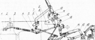
Reverse gear can only be engaged from a standstill and only with the main neutral position of the gear shift mechanism between first and second gears. If any gear is engaged, reverse gear cannot be engaged. This is ensured by the presence of a special recess on the shift disk and a protrusion on the reverse fork. When reverse gear is engaged, the protrusion on the fork fits into a notch on the shift disc. The reverse gear handle on the lever shaft is attached to the cone and is installed in the desired position until the nut is tightened. Gear shift mechanism of motorcycles "Ural" and "Dnepr" K 1,4 - screws, 2 - cover gasket, 3 - shift fork for 1st and 2nd gears, 5, 10 - fork shafts and pedals, 6 - shift fork 3 1st and 4th gears, 7, 28, 33 — washers, 8 — bolt, 9 — pedal, 11,31 — oil seals, 12 — oil seal spring, 13 — shift pedal bushing, 14, 15 — left cover and its gasket , 16 - return spring of the switching mechanism, 17 - pawl crank lever, 18 - washer, 19 - ratchet, 20, 34 - nuts, 21 - pawl, 22, 23 - crank and pawl axis of the switching mechanism, 24 - ring, 25, 27 — sector roller and its spring, 26 — sector 29 — right cover, 30 — wedge bolt, 32 — manual gear shift lever.
We recommend reading: Rules for registering an inheritance after the death of parents
How to change gears on a Ural motorcycle
This is the peculiarity of driving a KamAZ vehicle. A gearbox, the shift pattern of which is well studied and executed in this form, is distinguished by directional stability. The main point of dividing it into 2 modes is to facilitate engine operation when driving a car with different weights. Starting off on a loaded KamAZ (or with a trailer) is carried out in high gear with a crankshaft speed of 2600 rpm.
Please note => Documents Necessary for Registration of Ownership of an Apartment
Purpose, design and operation of the gear divider
The gear shift mechanism of the divider is designed to ensure that the required gear is engaged while the vehicle is moving and consists of a fork 14 (see Fig. 17) with nuts 15, a roller 13 of the fork 14, at the end of which a lever 16 is installed, and a pneumatic cylinder with a gear shift mechanism housing.
We recommend reading: Deed of gift with the right of lifelong residence
1 - spring housing; 2 — intake valve spring; 3 - gasket; 4 — inlet valve; 5 — intake valve stem; 6 — body; 7 — union nut; 8 - membrane; 9 — washer; 10 — housing cover; 11 — balancing spring; 12 – plug
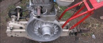
Transfer case Ural 4320, design and operation
Today we will talk about the transfer case of the Ural 5557 and 4320, and also discuss their design.
The transfer case is a unit that is responsible for distributing torque from the engine to certain drive mechanisms, and they most often increase the number of gears in the transmission.
The Ural transfer case distributes torque between the axles and increases the torque of the drive wheels, which guarantees stability while the Ural vehicle is moving. The Ural transfer case significantly affects the cost of the fuel mixture and the traction and speed parameters of the vehicle. Because of this, the cost of transporting various cargo directly depends on the correct choice of parameters owned by the transfer case itself.
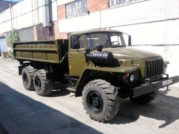
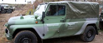
Ural 5557
In this article you can easily find answers to the most common questions:
- Transfer case of the Ural 5557, 4320 and its device;
- Functioning of the part as a transfer case of the Ural 5557, 4320;
- Common malfunctions of the transfer case of the Ural 4320, 5557;
- Adjusting the transfer case of the Ural 5557 and 4320.
Basic information about the transfer case of the Ural 5557 and 4320
The Ural 4230 and 5557 vehicles use a two-stage transfer case equipped with an asymmetrical cylindrical center locking differential with a power drive. The transfer case is mounted on the car frame using four rubber pads. The design of the transfer case of the Ural 5557 and 4320 is absolutely the same as that of the KamAZ 4310.
In the middle of the crankcase the following are located on bearings:
- Intermediate roller with gears of the lowest high gear;
- Rear drive shaft with middle axle. An asymmetrical cylindrical center differential is installed on these rollers;
- Front axle drive shaft;
- The primary roller has high and low gears, and a clutch is installed between them to change gears.
In order to maintain atmospheric pressure in the crankcase cavity, a fitting with a tube is installed on the bearing cover, connecting the crankcase to the atmosphere through a sealing system. The outlet tip of the tube is brought to a level above the maximum fordability to prevent water from being sucked into the crankcase while overcoming water obstacles.
The crankcase is made of cast iron, there is a hatch on top, the crankcase itself is one-piece, closed with a lid with an oil guide tray. Oil is poured into the crankcase through the top hatch with the cover removed or through the hole under the control plug, which is located on the rear wall of the crankcase. The oil is drained through the bottom hole, which is closed with a plug with a magnet. The crankcase is ventilated using a fitting, and its tube is included in the general sealing system of the units.
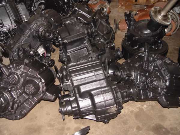
Transfer case Ural 4320
How does the transfer case Ural 4320 and 5557 function?
In the Ural 4320 and 5557, the torque supplied to the drive wheels can change. That is, the transfer case is considered at the same time an additional gearbox, which increases the number of gears and the limits of change in the gear ratio in the transmission. Thanks to the inclusion of a low gear in the gearbox and transfer case Ural 4320, 5557, it is possible to overcome high resistance to movement and stable movement of the machine at low speed.
The Ural 4320 and 5557 boxes with a rigid connection between the drive rollers of the drive axles have a ratio of torques that are supplied to the main gears of the drive axles, depending on certain parameters of the machine design and driving conditions. With the drive locked and driving straight on roads with good grip but little resistance and differences in wheel radii, certain drive wheels may slip and slide. This leads to faster wear of tires, transmission units and additional loads.
In order to eliminate these undesirable phenomena, a differential drive is used in this part. In this case, the torque is distributed between the drive rollers of the drive axles using a differential, which allows these rollers to rotate at angular speeds different from each other. Thanks to the properties of the installed differential, torque is distributed between the drive axles. That is, thanks to the transfer case differential, costs are reduced while driving on the road. Although the use of a drive differential while driving on slippery roads that have little grip can lead to a decrease or loss of vehicle maneuverability. To increase cross-country ability, vehicles are equipped with a device that blocks the differential.
Common malfunctions of the transfer case Ural 4320, 5557
Ural 4320 and 5557 boxes may have the following problems:
- Difficulty shifting gears of the transfer case differential unit. Most often, this problem occurs when burrs form on the couplings and pliers, the clamps jam, and the sliders bend. To eliminate this problem, it is necessary to clean the tongs and parts of the clamp, as well as put the sliders in order, straightening or replacing them.
- Loud noise. This problem can arise due to damaged gears and displacement of the rollers among the axial directions. In this case, it is necessary to check the adjustment of the bearings in the first and intermediate rollers, and also adjust the oil level.
- Oil leaks through the seals. This problem can occur due to wear of the seals during the formation of cracks. To solve this problem, it is necessary to replace damaged parts and clean the tube, which is responsible for sealing.
- The transmission and differential unit disengage on their own. Most often, this problem occurs due to damage to the switch forks and coupling connections, as well as due to movement of the rollers. To correct this problem, you need to replace worn parts and adjust the roller bearings.
We hope that our article gave you all the answers to your questions and now you have gained basic, basic knowledge on this topic. Good luck on the road and follow the traffic rules!
autodont.ru
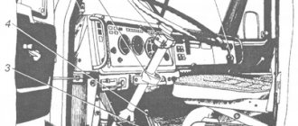
How to change speed on a Ural car diagram
- 1. Car tachograph
- 2. Engine Interface Unit (ECU)
- 3. Warning lamp block
- 4. Cruise control switch
- 4. Cruise control switch
- 5. Starter and instrument switch
- 6. Steering column switch for turns and headlights
- 7. Steering column wiper and washer switch
- 8. Electronic speedometer
- 9. On-board voltage indicator
- 10. Electronic tachometer
- 11. Coolant temperature gauge
- 12. Oil pressure indicator in the engine lubrication system
- 13. Fuel level indicator
- 14. Two-pointer pressure gauge
- 15. Auxiliary brake switch
- 16. Center differential lock switch
- 17. Unloading area headlight switch
- 18. Rear fog light switch
- 19. Cross-axle differential lock switch
- 20. Outdoor lighting switch
- 21. Turn signal breaker relay
- 22. Remote ground switch
- 23. Hazard switch
- 24. Rear fog lights R13
- 25. Cabin lift switch
- 26. Pump motor
- 27. Radiator grille open sensor
- 28. Thermobimetallic fuse
- 29. Cabin lift relay
- 30. Cabin heater valve.
- 31. Cabin heater motor
- 32. Electrically controlled left rear view mirror
- 33. Left turn signal repeater
- 34.56. Cabin lights
- 35. Cabin lantern illuminating the loading area
- 36.57. Door lamp switches
- 37. Front left contour lamp
- 38. Left side marker light
- 39,40,41. Road train sign lights
- 42. Road train sign switch
- 43. Rear view mirror control unit
- 44. Pads for connection with independent heater and heater
- 45. Illumination of cabin heater control.
- 46. Cab heater tap control switch.
- 47. Cab heater motor control switch
- 48. Right side marker light
- 49. Front right contour lamp
- 50. Electrically controlled rear view mirror, right
- 51. EDC diagnostic switch
- 52. ODI diagnostic switch
- 53. Portable lamp socket
- 54. Diagnostic connector
- 55. Right turn signal repeater
- 58. Platform lift switch
- 59. Dump trailer control switch
- 60. Heated mirror switch
- 61. Accelerator pedal
- 62. Fuse block F1
- 63. Fuse block F2
- 64. Fuse block F3
- 65. Starter relay R1
- 66. Relay for unloading terminal “15” R2
- 67. Relay for unloading terminal “15” R3
- 68. Wiper relay R4
- 69. Additional relay for rear fog lights
- 70. Side light relay R6
- 71. Fuse block F4
- 72. Low beam headlight relay R7
- 73. High beam headlight relay R8
- 74. Horn relay R9
- 75. Stop signal relay R10
- 76. Fuse block F5
- 77. Fuse block F6
- 78. Heated mirror relay for URAL cars
- 79. Headlight range control unit
- 80. Relay brake pedal position sensor
- 81. Center differential switch RK
- 82. Power take-off switch
- 83. Additional power take-off switch
- 84. Transfer case gear button
- 85. Transfer case gear selector
- 86. Center differential solenoid valve
- 87. Low gear solenoid valve RK
- 88. Neutral solenoid valve RK
- 89. High gear solenoid valve
- 90. Solenoid valve for power take-off
- 91. Additional power take-off solenoid valve
- 92. Windshield washer motor
- 93. Wiper motor
- 94.107. Additional high beam headlights
- 95.106. Fog lights
- 96. Left turn signal
- 97. Left low beam headlight module
- 98. Left headlight corrector motor
- 99. High beam headlight module with left side marker
- 100,101. Beep signal
- 102. High beam headlight module with right side marker
- 103. Right headlight corrector motor
- 104. Right low-beam headlight module
- 105. Right direction indicator
- 108,109,116,117. Side marker lights
- 110. Rear right lamp
- 111,112. Unloading area lights
- 113. Left rear lamp
- 114,115. Trailer sockets
- 118. Engine brake flap valve
- 119. Camshaft speed sensor
- 120. Pressure sensor URAL 6370
- 121. Low pressure and low temperature sensor top
- 122. Oil pressure and temperature sensor
- 123. Boost pressure and temperature sensor
- 124. Camshaft speed sensor
- 125. Fan control valve
- 126. Fan speed sensor
- 127. Ambient temperature sensor
- 128. Fuel measuring device
- 129,150,131,132,133,134. Fuel injection nozzles
- 135. Electronic control unit
- 136. Heating elements for air preheating
- 137. Air preheating relay
- 138,139. Heating elements for heating fuel fine filter
- 140. Fuel heating thermostat
- 141. Air dryer heating element
- 142. Water in fuel level sensor
- 143. Heating element for heating fuel in the coarse filter
- 144. Starter
- 145. Generator
- 146. Fuel level sensor
- 147,148. Rechargeable batteries
- 149. Ground switch
- 150,151. Wheel lock sensors
- 152. Sensor for turning on the center lock
- 153. Downshift sensor RK
- 154. Power take-off switch
- 155. Center lock sensor
- 156. Air filter clogging sensor
- 157,158. Pneumatic brake signal switches
- 159. Electro-pneumatic valve for lifting a dump trailer
- 160,161. Electro-pneumatic valve for platform lift
- 162,163,164. Emergency air pressure sensors
- 165. Parking brake sensor
- 166. Speed sensor
- 167. Neutral sensor
- 168. Clutch sensor
- 169. Reverse signal sensor
- 170. Electro-pneumatic valve for interaxle locking
- 171. Electro-pneumatic valve for inter-wheel locking
Please note => Where to go to get in line for an apartment