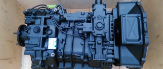
Recommendations for maintenance and repair of PSU on MAZ vehicles: how to bleed the clutch, video
The PGU unit on the MAZ is designed to reduce the force required to disengage the clutch. The machines contain units of our own design, as well as imported Wabco products. For example, PGU Vabko 9700514370 (for MAZ 5516, 5336, 437041 (Zubrenok), 5551) or PGU Volchansky AZ 11.1602410-40 (suitable for MAZ-5440). The operating principle of the devices is the same.
Design and principle of operation
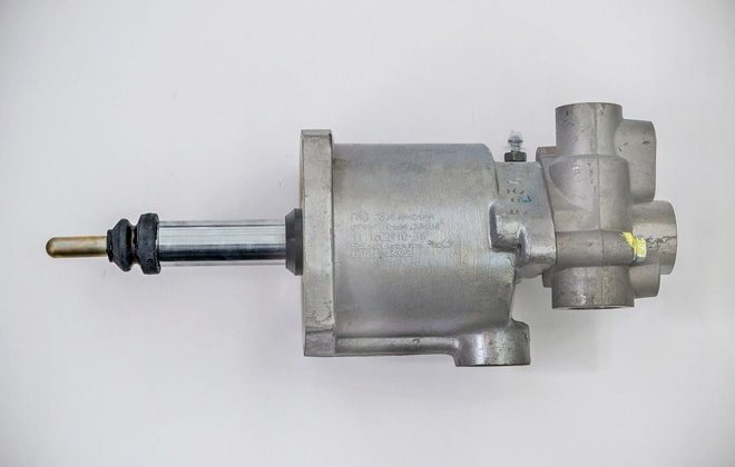
Pneumohydraulic amplifiers (PGU) are produced in several modifications, differing in the location of the lines and the design of the working rod and protective cover.
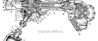
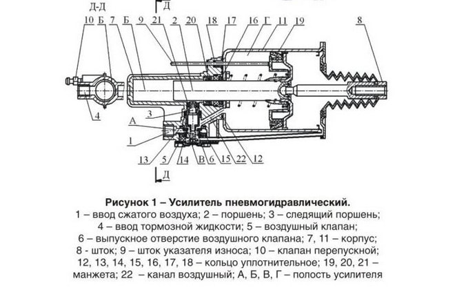
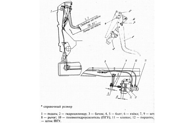
The CCGT device includes the following parts:
- a hydraulic cylinder installed under the clutch pedal, together with a piston and a return spring;
- the pneumatic part, which includes a piston common to pneumatics and hydraulics, a rod and a return spring;
- a control mechanism equipped with a diaphragm with a release valve and a return spring;
- valve mechanism (for intake and exhaust) with a common rod and an elastic element to return the parts to the neutral position;
- lining wear indicator rod.
To eliminate gaps, the design has preload springs. There is no play in the connections to the clutch control fork, which allows you to monitor the degree of wear of the friction linings. As the thickness of the material decreases, the piston is recessed into the depth of the amplifier body. The piston acts on a special indicator that informs the driver about the remaining clutch life. Replacement of the driven disk or linings is required when the indicator rod reaches a length of 23 mm.
The clutch booster is equipped with a fitting for connection to the standard pneumatic system of the truck. Normal operation of the unit is possible at a pressure in the air lines of at least 8 kgf/cm². To attach the PGU to the truck frame, there are 4 holes for M8 studs.
Operating principle of the device:
- When you press the clutch pedal, force is transferred to the piston of the hydraulic cylinder. At the same time, a load is applied to the piston group of the follower rod.
- The follower automatically begins to change the position of the piston in the pneumatic power section. The piston acts on the control valve of the follower device, opening the air supply into the cavity of the pneumatic cylinder.
- Gas pressure provides force on the clutch control fork through a separate rod. The tracking circuit automatically adjusts the pressure depending on the force of pressing the clutch pedal with your foot.
- After releasing the pedal, the fluid pressure is released, and then the air supply valve closes. The piston of the pneumatic section returns to its original position.
Clutch ZIL 130. Components and design.
In this article we will look at what main parts the ZIL 130 clutch and how you can adjust the “basket feet”.
Drive pressure disk ZIL 130 assembled - 1 piece
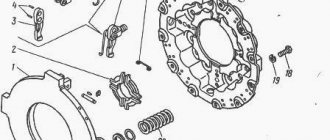
What motorists and craftsmen call among themselves a “basket” has an official technical name - drive pressure disk . It is designed to transmit torque from the engine flywheel to the driven clutch disc . To operate the pressure plate, the basket is equipped with a cast iron casing, through which the entire mechanism is bolted to the flywheel.
Sixteen springs are located under the casing. Their efforts exert pressure. In order to disengage the clutch, the pressure plate has four release levers ("claws" in the jargon).
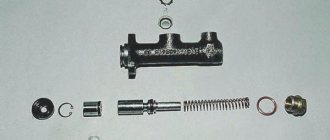
Driven disk ZIL 130 with friction linings assembled - 1 piece
A steel disc with friction linings on both sides (in the jargon “feredo” from the word ferodo, meaning friction heat-resistant composite material). The covers are secured with rivets. If you have a device and replaceable ferdos, it is possible to replace them to restore the performance of the disk. The photo below shows the thickness of the friction linings on the new disk.
During operation, due to friction and temperature overload, the disk wears out and becomes unusable. The damper part is also damaged (the springs fly off) and the guide splines wear out, as well as the steel base of the disc cracks.
In the central part of the disk there is a damper and a hole with splines that fit into the splines of the gearbox input shaft. The damper part with eight springs serves as a damper.
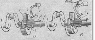
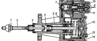
Release bearing ZIL 130 with clutch assembly - 1 piece
The release bearing is mounted on a coupling, which has stops on both sides. These stops allow you to move the clutch with the bearing using the clutch release fork . By depressing the clutch pedal, you move this fork. She, in turn, moves the “release” towards the “basket”, where the bearing rests on the release levers. The levers push the drive disc away from the driven disc and the clutch disengages as long as you keep the clutch pedal depressed. A detailed diagram of the clutch drive as well as a guide to adjusting the free play of the clutch pedal can be found in our article - Free play of the clutch pedal ZIL 130. Adjustment.
Thus, the ZIL 130 clutch is designed in the simplest way, without pneumatic hydraulic boosters and using a single driven disk. (For example, KamAZ, MAZ and KrAZ use two driven disks between which an intermediate plate is installed, and the squeezing force is increased using a PSU).
Removing the clutch for repair
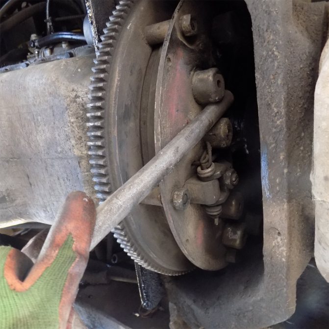
It is most convenient to dismantle it in an inspection ditch using a special winch for removing the gearbox. Procedure for dismantling:
- Unscrew the four nuts securing the gearbox to the engine casing.
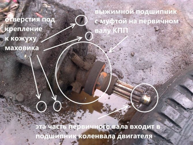
- Moving away from the engine, pull the gearbox off the mounting studs and lower it onto the pallet with a winch. There will be a release bearing on the gearbox input shaft.
- Remove the eight bolts securing the pressure plate to the engine flywheel.
- Carefully, holding the driven disk (which is sandwiched between the flywheel and the basket), remove the pressure disk.
Read more: Which is better Renault or Chevrolet
After this, you can inspect the condition of the parts: the working surface of the pressure plate pads, assess the wear of the friction linings of the driven disk. The working release bearing should rotate easily without making any extraneous sounds.
Malfunctions
Malfunctions of CCGT units on MAZ trucks include the following:
- Drive jamming due to swelling of sealing collars.
- Late response of the actuator due to thick fluid or sticking of the actuator follower piston.
- Increased pedal effort. The cause of the malfunction may be a failure of the compressed air inlet valve. If the sealing elements swell greatly, the follower mechanism jams, which causes a decrease in the efficiency of the device.
- The clutch does not disengage completely. The defect occurs due to incorrect adjustment of the free play.
- A drop in the liquid level in the tank due to cracks or hardening of the sealing lip.
ZIL clutch maintenance
The single-plate clutch on a car is not adjustable. If necessary, the clutch is removed and adjusted.
Clutch maintenance includes cleaning from dirt and timely tightening the bolts securing the clutch housing to the cylinder block. These bolts are tightened (tightening torque 8-10 kgm). The bolt heads are secured with plates, the ears of which are bent to the edge of the bolt.
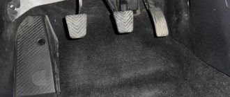
Caring for the clutch drive involves adjusting the free play of the pedal by changing the length of the rod. The clutch release bearing does not require lubrication during operation. The fork axles and clutch release pedal are lubricated according to the lubrication chart. See the figure for adjusting the clutch release drive.
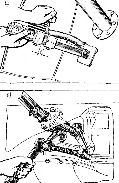
Rice. Adjusting the free play of the clutch pedal: a - measuring the free play of the pedal using a device; b — adjustment of the pedal free play; A - the amount of free play of the clutch pedal
Service
In order for the clutch system (single or double disc) of a MAZ truck to work properly, it is necessary to carry out maintenance of not only the main mechanism, but also the auxiliary one - the pneumatic amplifier. Maintenance of the unit includes the following work:
- The CCGT should first be inspected to identify external damage that could cause liquid or air leakage;
- tighten all fixing bolts;
- drain the condensate from the pneumatic booster;
- It is also necessary to adjust the free play of the pusher and the release bearing clutch;
- Bleed the PSU and add brake fluid to the system tank to the required level (do not mix fluids of different brands).
Additions to the design
If your clutch does not release the clutch disc, then you need to make some design changes.
1) Lengthen the clutch rod lever to increase the disc release stroke. At the bottom we weld a rod extension to the lever, as shown in the photo. This traction will give more pressing stroke of the clutch disc.
Read more: How many seats are there in a minibus?
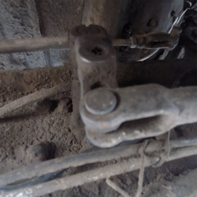
rod extender
2) Make inserts from the electrode under the clutch basket on the mounting bolts, as shown in the photo. These inserts will give less pedal travel for pressing the clutch disc and further adjustment.
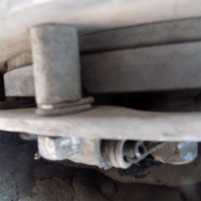
electrode inserts
Tool
1) 19 mm wrench to loosen the adjusting bolt.
2) Installation for turning the clutch itself
3) Adjustment key. You can make it yourself as shown in the photo.
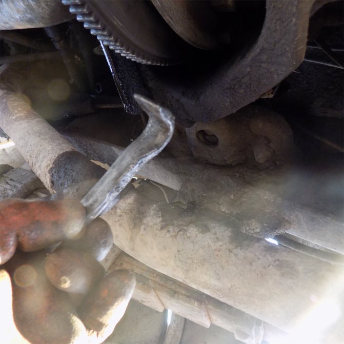
adjusting key
Using a 19 wrench, loosen the nut on the clutch foot of the adjusting bolt. Using the adjusting wrench, we turn the bolt and thereby move the clutch foot to the release plate. We leave about 2mm short of the release bearing for free movement, so that the bearing does not spin constantly.
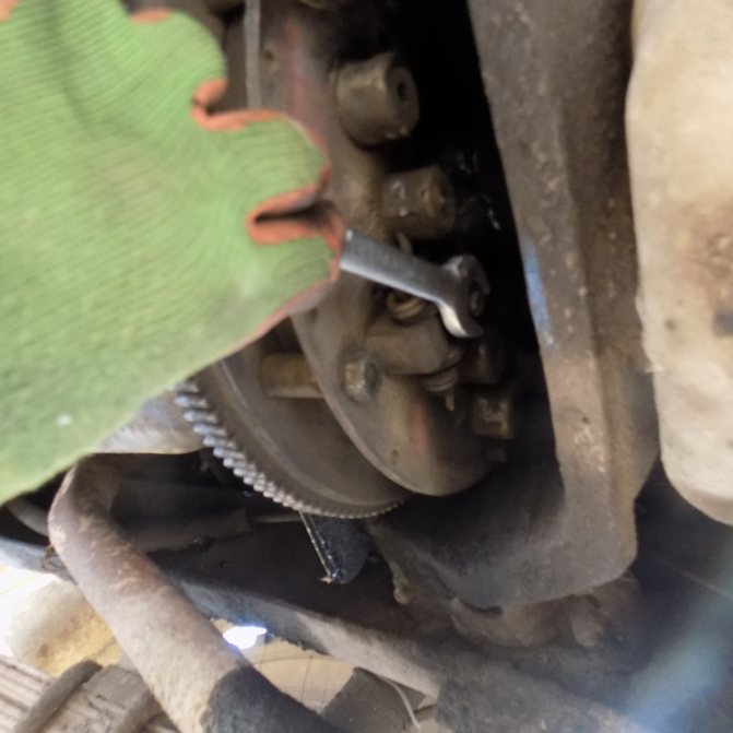
clutch adjustment
clutch adjustment
clutch adjustment
IMPORTANT
We adjust all the tabs equally so that the clutch disc moves out evenly. We turn the clutch with a mounting tool and look at the uniformity of the gap of each clutch tab, the operation of the clutch will depend on this.
After adjusting and checking, we tighten the locknuts on the adjusting bolt, as they often become loose and the entire adjustment gets lost.
How to replace
Replacing a MAZ PSU involves installing new hoses and lines. All units must have an internal diameter of at least 8 mm.
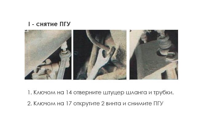
The replacement procedure consists of the following steps:
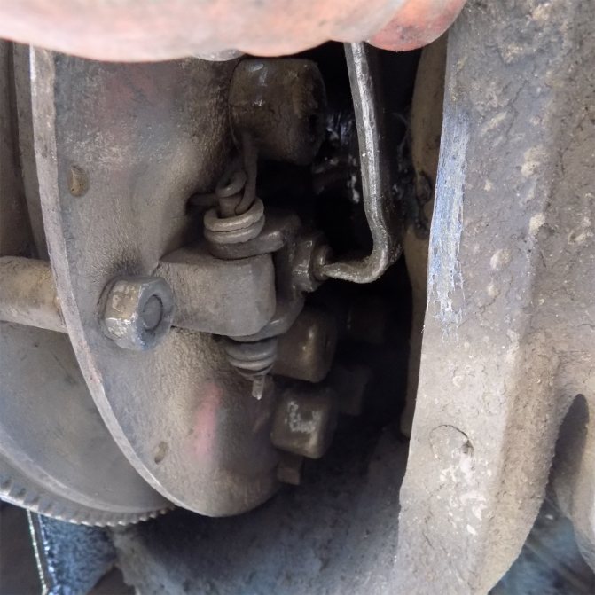
- Disconnect the lines from the old assembly and unscrew the mounting points.
- Remove the unit from the vehicle.
- Install a new unit in its original place and replace damaged lines.
- Tighten the mounting points to the required torque. It is recommended to replace worn or rusty hardware products with new ones.
- After installing the CCGT unit, it is necessary to check the misalignment of the working rods, which should not exceed 3 mm.
How to adjust
By adjustment we mean changing the free play of the clutch release clutch. The clearance is checked by moving the fork lever away from the spherical surface of the booster pusher nut. The operation is carried out manually; to reduce the force, it is necessary to remove the lever spring. A stroke of 5-6 mm (measured at a radius of 90 mm) is normal. If the measured value is within 3 mm, then it should be brought to normal by rotating the spherical nut.
After adjustment, you need to check the full stroke of the pusher, which should be at least 25 mm. The test is performed by fully pressing the clutch pedal.
At lower values, the amplifier does not ensure full disengagement of the clutch discs.
Additionally, the free play of the pedal is adjusted, corresponding to the start of operation of the master cylinder. The value depends on the gap between the piston and the pusher. A normal travel range is 6-12mm, measured across the middle of the pedal. The gap between the piston and the pusher is adjusted by turning the eccentric pin. The adjustment is performed with the clutch pedal fully released (until it contacts the rubber stop). The finger rotates until the required free play is obtained. Then the nut on the regulator is tightened and the safety pin is installed.
Correct bleeding of clutch 43253 Cummins
Then it’s worth inspecting other components - the reason lies there.
At the finish line, when all the air has been eliminated, you need to tighten the valve back and remove the hose. Next, a protective cap is put on the valve.
It is recommended to pour the pumped out brake fluid into a closed container and then store it.
It may be reused in the future.
However, this cannot be done right away - first you need to set aside time for it to settle, and before refilling it into the tank, you should pass it through a filter.
A paper watering can is perfect for this, used for straining paint, primer and varnish. Let your assistant press the clutch pedal all the way until air bubbles stop flowing from the hose into the container;
How to upgrade
There are two ways to pump the PSU correctly. The first is using a homemade supercharger. Pumping of the CCGT unit at MAZ is carried out as follows:
- Make a homemade pressure device from a plastic bottle with a capacity of 0.5-1.0 liters. Holes are drilled in the lid and bottom, into which nipples from tubeless tires are then installed.
- It is necessary to remove the spool valve from the part mounted in the bottom of the container.
- Fill the bottle 60-70% with fresh brake fluid. When filling, close the hole in the valve.
- Connect the container with a hose to the fitting installed on the amplifier. A valve without a spool is used for connection. Before installing the line, you need to remove the protective element and loosen the fitting by turning 1-2 turns.
- Apply compressed air to the bottle through the valve installed in the cap. The gas source can be a compressor with a tire inflation gun. The pressure gauge installed on the unit allows you to control the pressure in the container, which should be within 3-4 kgf/cm².
- Under the influence of air pressure, liquid enters the cavities of the amplifier and displaces the air present inside.
- The procedure continues until the air bubbles in the expansion tank disappear.
- After filling the lines, it is necessary to tighten the fitting and bring the liquid level in the tank to the required value. A level located 10-15 mm below the edge of the filler neck is considered normal.
How to install a PGU on MAZ 53366?
Let's consider the installation and replacement of MAZ CCGT. Before installing a new part, we recommend:
- Purchase hoses, new pipelines for use in hydraulics with a diameter of eight millimeters;
- As soon as the PGU is installed on the MAZ, look at the skew of each rod. The maximum skew rate should in no case exceed three mm;
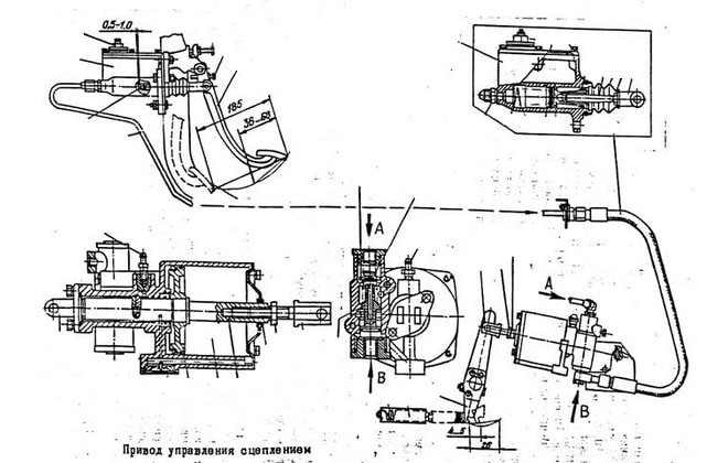
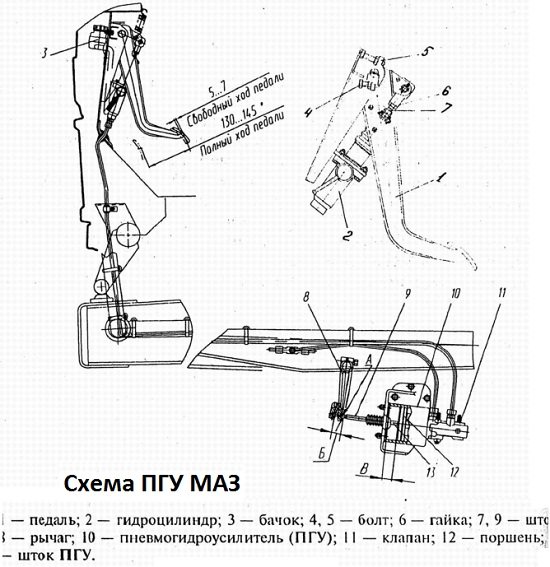
- Before installing the part, carefully study the MAZ CCGT diagram. This figure shows the placement of all elements of the system.
We adjust the stroke of the MAZ clutch PGU rod
When installing a part, it is important to correctly adjust the drive.
- Gently pull back the stem;
- Move the element to the other side;
- If the replacement is carried out correctly, the rod completely comes out of the surface of the spare part.
When installing the PGU on the MAZ 53366, do not forget to turn the lever away from the PGU. This way you will select all the gaps, and then measure the distance from the surface of the rod and lever (the counterbore is installed here).
If the size exceeds fifty mm, after installing the PGU on the MAZ it will work properly. If the gap is smaller, experts recommend removing the lever from the shaft surface and then mounting it 1 spline closer to the unit.
Try to measure the distance as accurately as possible. Only if the MAZ clutch PGU plunger is installed correctly will it be in good condition for a long time.
In addition, the plunger will not open the passage of liquid between the chamfer, which is installed at the end, and the edge of the seal.
Features of pumping
We will tell you in more detail about how to bleed the MAZ clutch PSU in the following articles of our blog. Now we want to clarify a couple of features that every car owner needs to pay attention to:
- Bleeding the drive, or rather its pedal, is not allowed to create force in the hydraulic part;
- After installing the PGU on a MAZ Zubrenok or MAZ 54323, it is necessary to do a check.
If a system malfunction occurs - wear of the disc linings and other elements - it is easier to buy a new part. After studying the MAZ PSU diagram, you can easily install the mechanism. The fact is that in most cases it is more difficult to repair MAZ CCGT units.
source
Adjusting the release levers (“claws”) of the ZIL-130 clutch basket
Clutch adjustment can be done on a dismantled pressure plate (for example, after replacing the clutch driven disc, or replacing the pressure plate pads or release bearing) or directly on the car through an open hatch in the flywheel. Let's consider the option of dismantling the gearbox and all clutch parts.
Dismantling is carried out in an inspection ditch using a special winch to remove the gearbox:
- After unscrewing 4 (four) fastening nuts, the gearbox is removed and lowered onto the pallet.
- Now unscrew the 8 (eight) bolts securing the pressure plate to the engine flywheel.
- Carefully, holding the driven disk (which is sandwiched between the flywheel and the basket), remove the pressure disk.
- All clutch parts are inspected.
- The release bearing is checked - it should rotate easily without making any extraneous sounds.
- Look at the working surface of the pressure plate feet. Determine the thickness of the friction linings of the driven disk.
When all the parts have been rebuilt and replaced with new ones, it is necessary to adjust the four levers of the pressure plate or, as they are simply called, the “legs” of the clutch basket. To do this, you will need a flat plate, which is used as a spare flywheel of the ZIL-130 engine. If there is none, you need to purchase it at a disassembly.
Without removing the assembled clutch pressure plate (basket) from the auxiliary flywheel (used as a device), it is necessary to adjust the position of the levers relative to the working surface of the pressure plate.
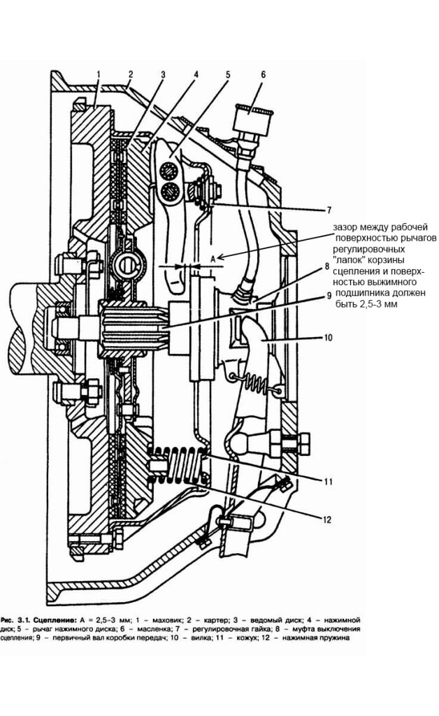
Rotating the adjusting nuts with a wrench, set all the levers in such a position that the distance from the working surface of the pressure plate to the tops of the spherical protrusions at the inner ends of the levers is within 39.7-40.7 mm. In this case, the ends of the levers must lie in the same plane, parallel to the working surface of the pressure plate with an accuracy of 0.5 mm, no more.
In the case where the clutch pressure plate is assembled in an adjustment device, the installation of the levers should be checked using a control plate, as shown in Fig. 1, b. In this case, the spherical protrusions of the levers should touch the control plate 2 mounted on the hub of device 1.