This term has other meanings, see Ural (meanings).
| Ural-375D | ||||||||||||||||||||||||||||||||||||||||||||||
| Total information | ||||||||||||||||||||||||||||||||||||||||||||||
| Manufacturer | Ural Automobile Plant (Miass, USSR) Ural Automobile Plant (Miass, Russia) | |||||||||||||||||||||||||||||||||||||||||||||
| Years of production | 1961—1992 | |||||||||||||||||||||||||||||||||||||||||||||
| Other designations | "Glutton" | |||||||||||||||||||||||||||||||||||||||||||||
| Design | ||||||||||||||||||||||||||||||||||||||||||||||
| Body type | all-metal | |||||||||||||||||||||||||||||||||||||||||||||
| Layout | front-engine, all-wheel drive | |||||||||||||||||||||||||||||||||||||||||||||
| Engine | ||||||||||||||||||||||||||||||||||||||||||||||
| ||||||||||||||||||||||||||||||||||||||||||||||
| Transmission | ||||||||||||||||||||||||||||||||||||||||||||||
| Gear ratios | ||||||||||||||||||||||||||||||||||||||||||||||
| 1st gear | 6,17 | |||||||||||||||||||||||||||||||||||||||||||||
| 2nd gear | 3,40 | |||||||||||||||||||||||||||||||||||||||||||||
| 3rd gear | 1,79 | |||||||||||||||||||||||||||||||||||||||||||||
| 4th gear | 1,00 | |||||||||||||||||||||||||||||||||||||||||||||
| 5th gear | 0,78 | |||||||||||||||||||||||||||||||||||||||||||||
| Reverse gear | 6,69 | |||||||||||||||||||||||||||||||||||||||||||||
| Switching | floor lever | |||||||||||||||||||||||||||||||||||||||||||||
The transfer case is two-stage. Gear ratios: 1st gear - 2.05; 2nd gear - 1.30. The main gear of the drive axles is double, the gear ratio is 8.91. efficiency=0.80;
Weight and dimensions characteristics Length 7350 mm Width 2690 mm Height 2680 (with awning 2980) mm Ground clearance 400 mm Wheelbase 3525 + 1400 mm Rear track 2000 mm Front track 2000 mm Weight 8400 kg On the market Similar models ZIL-131, KrAZ-255B Other information Load lifting capacity 4500 kg Tank volume 300+60 ← UralZIS-355MUral-4320 →
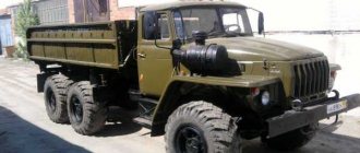
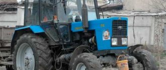
Media files on Wikimedia CommonsUral-375D
- an all-wheel drive off-road truck, produced at the Ural Automobile Plant in Miass since the early 1960s.
The truck was used to transport troops, cargo, and also as a chassis for strike weapons, such as the Grad multiple launch rocket systems; various modifications of it are still used in the national economy, usually with diesel engines.
A total of 110,000 pieces were produced [ source not specified 1132 days
].
In the Soviet army, the Ural-375D truck was replaced by the Ural-4320 model by 1982.
Characteristics
The truck was equipped with a ZIL-375 gasoline engine (V8, 7 l, 180 hp), a centralized tire pressure change system (from 0.5 to 3.2 kgf/cm²), a five-speed gearbox, and a double-disc clutch. On cars produced before 1965, transfer cases with a forced front axle were installed[4]. The transfer case lever had three positions:
- front axle off;
- the front axle is engaged, the center differential is locked;
- the front axle is engaged, the center differential is unlocked.
In 1965, a new transfer case of a simplified design was introduced with a permanently engaged front axle and an asymmetrical locking planetary-type center differential.
Steering mechanism with hydraulic booster. The service brake is a hydraulic drum with a pneumatic booster.
The original modification, Ural-375, had a folding tent roof and a flat windshield that folded onto the hood. In 1964, the car received an all-metal cabin from the Ural-377. The modernized vehicle received the Ural-375D index. On some machines, a winch with a traction force of 7000 kgf was installed at the rear of the frame.
The main disadvantage of the car was the gasoline engine with high fuel consumption and low overhaul life. Therefore, the diesel Ural-4320, which appeared in 1977, quickly replaced the Ural-375D, which, however, continued to be produced until the collapse of the USSR. The Ural-375D had higher cross-country ability compared to the Ural-4320. This is due to the lack of a speed controller, which made it possible to regulate the traction force on the wheels by adjusting the throttle position. The Ural-4320 is equipped with an all-mode speed controller, so when road resistance increases, the fuel supply automatically increases, which on soft soils leads to “breakdown” of the soft soil and slipping. For this reason, where the 375th will pass, the 4320th might not pass. [ source not specified 2621 days
]
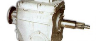
content .. 31 32 39 ..TRANSFER CASE OF URAL-375D CAR
The transfer case (Fig. 46) is mechanical, two-stage with an asymmetrical center differential.
The transfer case serves to distribute and transmit torque to the front and middle axles and through the drive shaft of the middle axle gearbox to the rear axle.
The transfer case is mounted on the car frame on two brackets with rubber cushions. The transfer case and center differential mechanisms are mounted in a cast one-piece housing 30. All transfer case gears are constantly meshed with a spiral tooth.
The primary shaft 33 rotates in tapered roller bearings 24, closed with covers. An oil seal is pressed into the front cover 23, mounted on adjusting shims. A sealing system fitting is screwed into the back cover 31, mounted on a sealing gasket.
The inner race of the rear bearing should be tightly clamped with a nut secured with a plate washer.
On the input shaft, on bronze bushings 26 of the floating type, the drive gears of the lowest 29 and highest 25 gears rotate freely.
The input shaft has splines at the front, middle and rear. A flange 22 for fastening the propeller shaft is installed on the splines of the front part; A reflector is welded to the flange. A gear shift carriage 28 is installed on the splines of the middle part, which alternately engages with the crown of the corresponding gear 25 or 29.
The splines at the rear of the shaft serve to transmit torque to the auxiliary power take-off shaft, which is connected to the input shaft by a movable clutch.
The gears are engaged using lever 5 (see Fig. 47) using fork 43 (see Fig. 46) and rod 44. The gear shift lever can be set in three positions: forward - high gear is engaged, middle - neutral, rear - low gear is engaged broadcast.
The intermediate shaft 36 rotates in two tapered roller bearings, closed by covers 35 and 20. Adjusting shims are installed under the rear cover 35. The inner races of the intermediate shaft bearings should be tightly tightened with nuts and secured with plate washers.
The gears of the lowest 38th and highest 19th gears sit motionless on the splines of the intermediate shaft. Gear 38 is in mesh with the drive gear of the lower shaft 9.
The speedometer drive gear 40, mounted on the front end of the intermediate shaft, is meshed with the driven gear 42, which is installed in the cover 20 using a fitting 41.
To distribute torque between the driving axles of the vehicle in proportion to the loads falling on these axles, an asymmetrical center differential is introduced into the transfer case, distributing torque between the front axle and the rear bogie axles in a ratio of 1:2.
The split housing of the center differential consists of two cages bolted to the base of the drive gear ring of the lower shaft 9. The cages are mounted on ball bearings.
In the front differential cage 11 and in a support washer connected to it with bolts, four satellites 18 are installed, freely rotating on bronze bushings. The satellites are meshed with the sun gear 10 and the ring gear 7. The sun gear sits on the splines of the front axle drive shaft 14, which can rotate independently of the differential races on a bronze bushing and ball bearing.
The ring gear also rotates freely on a bronze bushing pressed into the rear differential race 6. Shaft
rear axle drive, one splined end enters the main gear, and the other end rests on a ball bearing.
When the differential is working (unlocked), constant and uniform traction of all axles is ensured and the circulation of parasitic power is eliminated. Depending on road conditions, the differential may be switched off (locked)
van), and then the drive shafts of the front and rear wheels rotate as one unit.
The differential is locked by clutch 12 using fork 49 and rod 46. In the forward position of the clutch, the differential works, in the rear position it is turned off. According to the clutch positions, the lever can also be installed in two positions.
The gear shift clutches and differential locks are fixed in the appropriate positions by balls 47 and springs 48 located in the housing 45.
The top hatch of the transfer case is closed with a stamped cover 27, to which an oil trap is welded. The oil trap is designed to lubricate the front bearings of the primary and intermediate shafts.
In the bearing caps 17 and 4, oil seals and oil sump rings 2 are installed. On the outer surfaces of the oil sump rings, helical grooves are cut, guiding the oil when the shafts rotate from the oil seals into the crankcase. The spiral of the helical groove is made in different directions: for the front axle drive shaft - left, for the rear axle drive shaft - right. In accordance with their purpose, the letters P (front), 3 (rear) are stamped on the oil sump rings.
When assembling the transfer case, it is necessary to ensure that the oil sump rings are installed correctly, otherwise significant oil leakage through the oil seal is inevitable. The internal cavity of the transfer case housing communicates with the atmosphere through the tubes of the sealing system.
The transfer case control levers rotate freely on shaft 7, mounted in bracket 8 (Fig. 47). The bracket is secured with three bolts to the gearbox housing.
The levers with rods 9 and 10 are connected to drivers 11 and 12. The drivers with bushings pressed into them rotate freely on rollers pressed into bracket 13. The bracket is mounted on the transfer case housing. Pressure springs 6 eliminate vibration of levers 4 and 5 and prevent premature wear of their bushings.
Rice. 47. Transfer case control: 1 — position of the lever with the differential locked; 2 — lever position when downshift is engaged; 3 — lever position with overdrive engaged; 4 — differential lock lever with the differential unlocked; 5 — gear shift lever in neutral position; 6 — preload spring; 7 — roller of control levers; 8—control lever bracket; 9 — differential lock rod; 10 — gear shift rod; 11 — gear shift lever; 12 — differential locking lever; 13 — bracket for control arms; 14 — gear shift fork rod; 15 — differential lock rod
content .. 31 32 39 ..
Modifications
- Ural-375 - had a cabin with a folding canvas awning. Produced from 1961 to 1964.
- Ural-375D - had an all-metal cabin. Produced since 1964.
- Ural-375A - chassis with an extended frame for installing a K-375 van body.
- Ural-375E - chassis for installing various equipment.
- Ural-375S is a truck tractor.
- Ural-375K - for operation in the Far North.
- Ural-375T - not mass-produced, prototype for Ural-375N[5].
- Ural-375N is a national economic vehicle. External differences from the Ural-375D: there was no air intake pipe, the body was a wooden platform with three opening sides, wheels without centralized pressure control, tire size - 1100x400-533, a spare wheel under the body (and not between it and the cabin).
Application
Ural-375 was used primarily in the armed forces, where many complexes were created on its basis:
Battery of the Grad multiple launch rocket system on the Ural-375D chassis
- launcher 2B5 MLRS 9K51 "Grad"
- tank trucks ATs-5-375, ATs-5.4-375, ATsG-5-375
- tanker ATMZ-5-375
- truck cranes 8T-200, 8T-210, 9T-31
- radar station P-18 1RL131 “Terek”
- mobile power station ED16-T/230-RAO
The car also found application in the national economy, in particular it was used by oil workers and geologists, and in some places it is still in use due to its exceptional cross-country ability. As a rule, in the national economy, the ZIL-375 gasoline engine with high fuel consumption is replaced by more economical and powerful diesel engines YaMZ-236 and YaMZ-238, which significantly improves many vehicle performance. [ source not specified 1660 days
]
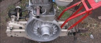
Gear shift diagram
The shift pattern may differ depending on the specific model, since not all trucks are equipped with the YaMZ-236 three-way gearbox, which has five forward gears and one reverse gear.
With the help of a gear, which is installed in the box, not only first gear is switched, but also reverse gear. As for the remaining gears, that is, second, third, fourth, fifth, they are synchronized.
If you look at the type of transfer case, we can say that it is distinguished by the presence of high and low gears, as well as the ability to lock and unlock the differential.
Regardless of which specific gearbox is used on the Ural truck, there is no doubt about its high quality, since it has been tested by time. Gearboxes made in the Urals have long proven themselves to be the best. They are reliable, while ensuring the performance of all the necessary tasks that such a car must perform while driving. We are talking not only about empty, but also fully loaded cars driving on both regular roads and real off-road conditions.
Notes
- ↑ 12345678
Engine ZIL-375 — Engine catalog — AutoInf - Magazine "AUTOTRAK" :: Archive Archived January 18, 2012.
- Car Ural 375D. - M.: Vneshtorgizdat, 1969. - 211 p.
- Golodovsky Ya. E.
Off-road trucks (GAZ-66, ZIL-131, Ural-375). - M.: Voenizdat, 1968. - 400 p. — 65,000 copies. - Ural-375T
Ural gearbox maintenance
In order for the transmission on your truck to last as long as possible, you must follow some simple rules. Firstly, we are talking about high-quality and timely checkpoint maintenance. So, in the plug there is a special indicator that shows the oil level. This level must be carefully monitored, changing the oil if necessary. You also need to fill the oil correctly. To do this, it is better to completely follow the lubrication map.
In the event of the slightest malfunction, they should never be overlooked. Worn parts must be replaced with new ones or at least repaired.
Separately, it should be said about the rules for towing a Ural car. When the distance exceeds 150 kilometers and the engine is running, it is important to remember to remove the intermediate driveshaft. If you do not want to remove the intermediate cardan, then towing should be done at a speed not exceeding 40 kilometers per hour.