The T-170 bulldozer is a tracked special equipment that is used in construction and agriculture, on soils with low bearing capacity (swampy, snow, frozen soil).
The first T-170 tractor rolled off the assembly line in the spring of 1988 and immediately established itself only on the positive side, and a little later the T-170 bulldozer became the most popular special equipment. The technical characteristics of the T-170 are at a very high level, and it is thanks to such technical indicators that it gained its popularity.
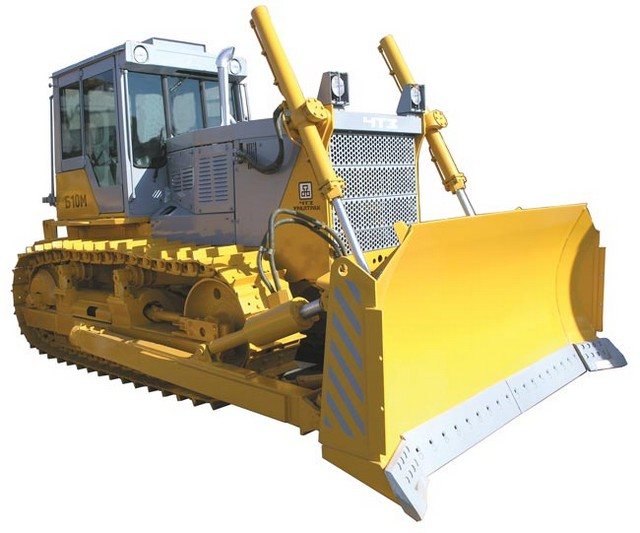
Bulldozer T-170
The T-170 is a slightly improved modification of the T-130 tractor. The T-170 is equipped with a more powerful engine of the same series with a torque reserve of 25%, and it is also capable of running on various types of fuel: diesel, kerosene, gas condensate. A bulldozer-ripper or a pipe layer is manufactured on the basis of a tractor. At the end buyer's request, the tractor can be equipped with: a pre-heater, various types of starting equipment and other options; all this is agreed upon when purchasing the equipment.
Construction of the T-170 bulldozer
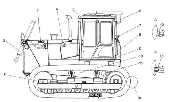
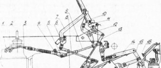
Structure of the bulldozer T-170
1 – running system; 2 – installation of long-stroke cylinders; 3 – hydraulic system; 4 – diesel; 5 – cabin; 6 – operator protection device “ROPS-FOPS”; 7 – electrical equipment; 8 – fuel tank; 9 – platform; 10 – supporting system; 11 – transmission; 12 – rigid towbar; 13 – pendulum tow hitch.
Engine
The T-170 bulldozer is equipped with the D-160.11 engine and its modification D-180.111-1Yu, which have a service life of 8,000 hours before overhaul. With the update, the engine became more powerful, reaching 180 hp, and the torque also increased. A turbocharged engine is able to “digest” different types of fuel: diesel fuel, kerosene, gas condensate. Starting is carried out from a P-23U carburetor starting engine or an electric starter. The installed optional pre-heater PZD-30 allows the bulldozer to be used in arctic conditions with temperatures down to -50?C.
Transmission
The transmission uses a four-shaft constant mesh gearbox. As standard, it is equipped with 8 forward and 4 reverse gears. For installation on some modifications of the bulldozer, the first two gears of the normal and accelerated ranges can be blocked, which turns the box into a 6-speed one.
Hydraulic system
The hydraulic system uses a gear hydraulic pump NSh-100, mounted on the engine. Purification of the working fluid is ensured by Regotmas filter elements. Degree of purification - particles up to 25 microns in size. The configuration of the entire hydraulic system depends on the attachment used and may vary.
Electrical equipment
The on-board voltage of the bulldozer is 24 V. Depending on the modification of the bulldozer, 2 batteries are installed: 6ST-182EMS in the case of using an electric starter engine starting system or 6ST-75TM if a starting motor is used. The 1 kW generator is equipped with an electronic voltage regulation system.
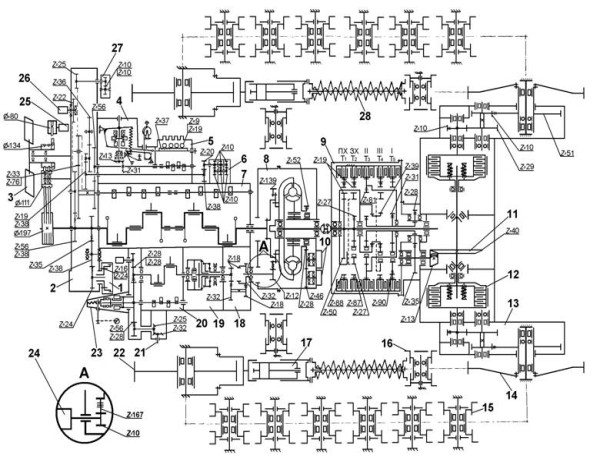
Kinematic diagram of the T-170
1 – hydraulic system pump; 2 – casing of diesel distribution gears; 3 – fan; 4 – diesel regulator; 5 – fuel pump; 6 – oil pump; 7 – diesel; 8 – torque converter; 9 – gearbox; 10 – hydraulic pumps; 11 – main gear; 12 – side clutch; 13 – final drive; 14 – driving wheel; 15 – support roller; 16 – support roller; 17 – tension mechanism; 18 – starting motor gearbox; 19 – starting motor clutch; 20 – starting motor; 21 – turning mechanism; 22 – tension wheel; 23 – starting motor regulator; 24 – electric starter; 25 – generator; 26 – diesel cooling system pump; 27 – pump of the hydraulic control system; 28 – delivery mechanism.
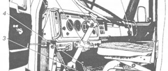
List of plates and markings on the tractor
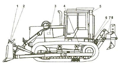
Markings on the T-170 tractor
1 Markings on bulldozer equipment - the symbol of the manufacturer and the number are stamped on the rear side of the blade on the right in the upper part.
2 The plate for a tractor with bulldozer or bulldozer and ripper equipment is attached to the rear side of the blade on the right in the upper part.
3 The engine plate is attached to the right side of the engine above the fuel pump, the engine number is duplicated in the same place and is covered by the plate.
The turbocharger nameplate is attached to the flange of the turbocharger housing.
The fuel pump nameplate is attached to the fuel pump assembly.
The starting motor number is stamped on the starting motor block.
4 The gearbox number is stamped on a horizontal platform: - in the upper part of the rear cover of the planetary gearbox housing; - in the upper part of the gearbox housing of a manual transmission.
The number of the torque converter (GTR) is stamped on the vertical plane of the upper part of the GTR housing.
The clutch number is stamped on the clutch flange.
5 The tractor plate is attached to the rear wall of the onboard clutch housing on the right side in the upper part. Inaccessible when loosening equipment is installed.
6 The tractor number is imprinted on the side clutch housing at the top right.
7 The number of the side clutch housing is stamped on the rear wall of the side clutch housing at the top left.
8 Marking on loosening equipment - the symbol of the manufacturer and the number are stamped on the working beam on the top left.
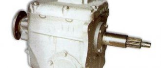
Gearbox T-170 T-130 B-10
When assembling the gearbox of the T-170, T-130 tractor, the following requirements must be observed:
— rubbing surfaces, smooth gear holes and outer surfaces of plain bearing bushings are lubricated with transmission oil;
— the inner and outer rings of cylindrical bearings must be of the same group;
— the front cover and gearbox housing of the bulldozer T-170, T-130 should not be disassembled and processed as an assembly; the same serial numbers are marked on their upper surfaces;
— before installation on the shafts, roller and ball bearings are heated in an oil bath to a temperature of 80 ... 100 ° C;
— the lower shaft of the T-170 (T-130) gearbox is equipped with a bevel gear of the main gear; dismantling of this conical pair is not allowed;
— movement of the gearshift levers of the tractor T-170, T-130 from the neutral position to the right or left until failure should occur with a smoothly increasing force of elastic resistance of the springs;
— the movement of the rollers with forks must be free, with clear fixation of the neutral and working positions;
— the rotation of the levers of the clamp rollers must be free, without jamming in the neutral position of the gear shift lever and in positions corresponding to the full engagement of any gear; When the clamps are locked, movement of the rollers is not allowed;
— when moving the roller with the fork from the neutral position to the working position, the other roller must be securely locked with a ball lock in the neutral position;
— the studs are installed on red lead with iron grease;
— the normal gap between the hole in the gears and the outer surface of the bushings should be 0.12 ... 0.21 mm; permissible gap 0.3 mm;
— the normal lateral clearance between the splines of the upper shaft of the T-130/170 gearbox and the gear bushings should be 0.146 ... 0.424 mm; permissible gap 1.0 mm;
— the gearbox of the tractor T-170, T-130 is supplied as spare parts complete with a bevel gear.
When replacing the gearbox, the main gear bevel gear must be replaced at the same time.
The serial number of the bevel gear is marked on the gearbox housing.
Assembling the upper gearbox shaft of the bulldozer T-170, T-130
Fig.4. Upper shaft of gearbox T-170, T-130
The upper shaft of the T-170, T-130 gearbox (1) (see Fig. 4) is installed in the fixture with the surface with the keyway down.
Sequentially install ring 3, bushing b, gear 4, couplings 5 and 8, second bushing b, gear 7, second couplings 5 and 5, third bushing b, gear 9 and bushing 10 onto the shaft.
When installing couplings and bushings, the grooves with the removed splines are aligned with the lubricant supply channels in the upper shaft.
Install clamp 12 with spring 11 on sleeve 10 with the flat facing towards the lower shaft and align the lubrication holes. Install gear 13 and bushings 14 and 19 on the upper shaft.
Having moved the parts installed on the shaft until they stop, install the gasket package 18 so as to provide a gap A of 0.05 ... 0.3 mm between the sleeve 19 and bearing 15.
Gaskets 2 mm thick are installed on both sides of the bag. Heat the bearing 15 in an oil bath to a temperature of 80 ... 90 °C and, having pressed it onto the shaft, put on the lock washer 17 and tighten it with a nut 16 with a tightening torque of 450 ... 550 Nm.
Bend the lock washer onto the edge of nut 16. Turn the upper shaft over. Bearing 2 is heated in an oil bath to a temperature of 80 ... 90 °C and pressed onto the shaft until it stops.
On the assembled upper shaft of the T-170, T-130 gearbox, the gears should rotate freely on the bushings, and the couplings should move without jamming.
Assembly of the first intermediate shaft of the T-170, T-130 gearbox
Fig.5. The first intermediate shaft of the T-170, T-130 gearbox
The first intermediate shaft of the T-170, T-130 gearbox (15) (see Fig. 5) is installed in the device with the splined surface up and sleeve 14, gears 2, 3 and 4 and ring 13 are put on it.
Next, assemble gear 7 with rings 5, bearings 12, spacer 6 and press it onto the shaft until it stops against ring 13.
Put on ring 11. Heat bearing 8 in an oil bath to a temperature of 80 ... 90 °C and press it onto the shaft until it stops against ring 11.
Install the lock washer 9, screw the nut 10 with the machined end to the washer, tighten it with a tightening torque of 450 ... 550 Nm and lock it with the washer 9.
Turn the shaft over. Heat bearing 1 in an oil bath to a temperature of 80 ... 90 ° C and press it onto the shaft until it stops.
Assembly of the second intermediate shaft of the T-170, T-130 gearbox
Fig.6. The second intermediate shaft of the gearbox of the bulldozer T-170, T-130
The second intermediate shaft of the bulldozer gearbox T-170, T-130 (see Fig. 6) is installed in the device with the threaded end up and assembled with gear 10, bushing 9, gears 8 and 7, bushing 6, gears 5 and 4.
Having moved the gears and bushings until they stop, install the gasket package 3, ensuring a gap A = -0.05 ... 0.3 mm between the end of gear 4 and the end of the inner ring of bearing 2.
Gaskets 2 mm thick are installed on both sides of the bag. Bearing 2 is heated in an oil bath to a temperature of 80 ... 90 °C and installed on the shaft.
Turn over shaft 1. Heat bearing 11 in an oil bath to a temperature of 80 ... 90 °C and press it onto the shaft until it stops. Install retaining ring 12.
Assembly of the lower shaft of the bulldozer T-170, T-130 gearbox
Fig.7. Lower shaft of gearbox T-170, T-130
The lower shaft of the T-170, T-130 gearbox (see Fig. 7) is installed in the fixture with the bevel gear down.
Bearing 17 is heated in an oil bath to a temperature of 80 ... 90 °C and installed on the shaft until it touches the collar.
Next, install sequentially bushings 16 and 11, gear 15, couplings 14 and 9, second bushing 11, gear 13, spacer 12, third bushing 11, gear 10, couplings 8 and 9, bushing 7, gear 6, ring 5 and bushing 4.
Having moved all the parts until they stop, install the gasket package 3 so as to provide a gap A = 0.05...0.3 mm between the end of the bushing 4 and the inner ring of the bearing 2.
Spacers 2 mm thick are placed on both sides of the bag. Bearing 2 is heated in an oil bath to a temperature of 80 ... 90 ° C and pressed onto the shaft until it stops.
When assembling the lower shaft of the T-170, T-130 gearbox, it is necessary to align the groove with the removed spline in the couplings and bushings with the holes for supplying lubricant to the bushings in the shaft.
The lower shaft of the gearbox is installed complete with a final drive bevel gear tested for tooth engagement.
Assembly of gearbox shafts T-170, T-130 with front cover
The upper shaft 4 is installed on the bench table so that the distance from the end of the teeth of gear 8 (see Fig. 4) to the plane of the device is (126 ± 0.06) mm.
This size is set using a template. The specified size ensures the distance Г = (126 -0.2) mm in the assembled gearbox (see Fig. 8).
Fig.8. Gearbox T-170, T-130 in section
Install the first intermediate shaft T-170, T-130 in the device so that the protrusion of the ends of the teeth of gear 8 (see Fig. 1) of the upper shaft in relation to the ends of the teeth of gear 2 (see Fig. 5) of the first intermediate shaft is (2 ± 0.5) mm.
Install the shafts into the fixture at the specified dimensions by rotating the handles.
Install the second intermediate shaft 5 in the device so that the gap between the ends of gear 2 (see Fig. 5) of the first intermediate shaft and gear 7 of the second intermediate shaft is within (4 ± 0.5) mm.
Install the lower shaft of the T-170 (T-130) gearbox. Place the front cover on the pins and the plane of the device and press it with clamps.
Fig.9. Gearbox T-170, T-130 type B
Putting the gasket package 108 (see Fig. 9.10) on the flange of the upper shaft bearing housing 99 and the sealing ring, install the bearing housing in the front cover 2.
Fig. 10. Gearbox T-170, T-130 type A
Press the outer ring of bearing 109 until it stops into the shoulder of the bearing housing of the upper shaft 99.
Bearing 100 is heated in an oil bath to a temperature of 80 ... 90C and pressed onto the upper shaft 103 until it stops against bearing 109 with the number on the ring facing up, an oil deflector 106 and a key 105 are installed.
Lubricate the gasket 107 with sealant and install it on the flange of the bearing housing of the upper shaft 99 and install the cover 27 of the upper shaft and secure it together with the bearing housing with bolts 25 with spring washers 26.
Place rubber ring 104 on the upper shaft cover. Flange 7 is heated to a temperature of (260 ± ± 10) °C and pressed onto the upper shaft 103. Screw the nut 102 onto the upper shaft 103 until it touches the flange 7 and lock it with two bolts 101 with spring washers.
Check the dimension D (126 ± ± 0.2) mm and, if necessary, adjust with gaskets 108.
Place the gasket package 96 and the sealing ring onto the bearing housing 98 of the first intermediate shaft of the T-170, T-130 gearbox, and install it in the front cover 2.
Press the outer ring of bearing 109 into the bearing housing 98 until it stops, with the number on the ring facing up.
Bearing 100 is heated in an oil bath to 80 ... 90 °C and pressed onto the first intermediate shaft 80 until it touches bearing 109.
Install the lock washer with the inner tendril into the keyway of the shaft 80, screw the nut 97 with the machined end to the washer and bend the ends of the washer on the edge of the nut.
Lubricate the gasket with sealant on both sides, install it and cover 4 on the flange of the bearing housing 98 and secure with bolts 25 with spring washers 26.
Check the size (2 ± 0.5) mm and, if necessary, adjust with shims 96.
Place the gasket package 95 and the sealing ring onto the bearing housing 93 of the second intermediate shaft and install it in the front cover 2.
The outer ring of the bearing 90 is pressed into the bearing housing 93 until it stops against the collar with the number on the ring facing up.
Bearing 92 is heated in an oil bath to 80 ... 90 °C and pressed onto the second intermediate shaft 83 until it touches bearing 90.
Install the lock washer with the inner tendril into the keyway of the shaft 83, screw the nut 94 with the machined end to the washer and bend the ends of the washer on the edge of the nut.
Lubricate the gasket on both sides with sealant, install it and the cover 32 on the flange of the bearing housing 93 of the second intermediate shaft of the T-170, T-130 gearbox and secure it with bolts 25 with spring washers 26.
Check the size (4 ± 0.5) mm and, if necessary, adjust with shims 95.
Place the gasket package 88 and the sealing ring onto the bearing housing of the lower shaft 85 and install it in the front cover 2.
Press the outer ring of the bearing 90 into the bearing housing until it touches the shoulder.
Install the lock washer with the inner tendril into the keyway of the lower shaft 85, screw the nut 91 with the machined end to the washer and bend the ends of the washer onto the edge of the nut.
The thickness of the package of adjusting shims 88 is finally set when adjusting the size D = 83.9 ± ±0.1 mm (see Fig. 8).
Assembly of gearbox housing T-170, T-130
The T-170, T-130 gearbox housing is mounted on a stand.
Lubricate the bearing seats in the box body with gear oil and install the outer rings of bearings 76, 78, 82 and 84, placing the slots for the stoppers opposite the holes in the housing.
Install the stopper 74 into the housing hole until it stops in the bearing seat 76 and press the plug 73 until it stops into the housing seat.
Stoppers and plugs for bearings 78, 82 and 84 are installed in the same way.
Put the rubber ring 77 on the cover 79 and install it in the T-170, T-130 gearbox housing.
Install the retaining ring 81 into the groove of the box body.
Press pins 3 and 86 (if they were pressed out) and bushing 110 into the housing holes.
Lubricate the gasket on both sides with sealant and, together with cover 34, install it on the gearbox housing and secure it with nuts 35 and spring washers.
Screw the magnetic plug 33 with the gasket into the cover 34.
Assembling the front cover with the gearbox housing of the T-170, T-130 tractor
The T-170, T-130 gearbox housing and the front cover must have the same serial number. The housing is installed on the stand with the mating plane down and secured with clamps.
Lubricate gasket 87 on both sides with sealant and install it on the gearbox housing flange.
Install the front cover 2, complete with shafts, onto the box body so that the pins 86 fit into the holes in the front cover. Insert spring 72 into the housing hole.
Secure the front cover with 2 bolts 29 and washers. Turn the gearbox and set the lower shaft 85 to the dimension D = (83.9 ± 0.1) mm between the end of the shaft and the plane of the T-170, T-130 gearbox housing with gaskets 88.
Dimension D is measured with the lower shaft 85 shifted inside the gearbox.
Lubricate the gasket with sealant and install it on the flange of the bearing housing 89.
Screw the lubricant supply fitting into the cover 28, install it on the gasket and, moving within the gap between the bolts and holes, find a position where when the lower shaft 85 rotates, the fitting does not touch it.
In this position, the cover is secured with bolts 25 with clamping washers 26.
Screw two pins into the holes of the front cover 2 and, putting tripods 30 on them, secure them with nuts 31.
Installation of gear shift rollers, forks and shanks of the bulldozer T-170, T-130 gearbox
Turn the gearbox housing T-170, T-130 with the hatches of the switching mechanisms upward.
Install the fork 65 into the annular groove of the upper shaft engagement clutch 103.
The roller 66 is installed in the body of the T-170, T-130 gearbox, passing it through the holes of the fork 65, and the shank 38 is secured to it.
Install two balls 111 into bushings 110.
Insert the fork 64 into the annular groove of the engagement clutch of the upper shaft 103 and install the second roller 66 into the hole of the box body, passing it through the hole of the fork 64.
Install the shank 38 on the roller 66, secure the shanks 38 to the rollers 66 with stoppers.
The forks 64 and 65 are secured with wedges 71 and nuts 62 with the outer gear coupling centrally located relative to the inner one and the roller 66 in the neutral position.
The nuts are secured with 62 locking plates 63. Dimension B should be (21.5 ± 0.8) mm. The rollers must move freely.
The plug is pressed in and the covers 24 are installed, using adjusting shims to maintain a gap of 0.3+1.2 mm between the cover and the ends of the rollers in the on position, and they are secured with bolts 5 with spring washers.
Similarly, install forks 36 and 37 and rollers 66 for the lower shaft 85. Install the fitting for supplying lubricant to the upper shaft.
Lubricate the gasket with sealant, place it on the oil pump flange and install the pump with the oil receiver in the hatch of the gearbox housing on the pins and secure it with bolts and spring washers.
Assembly of gear shift mechanisms for bulldozer T-170, T-130
When assembling the left shift mechanism, spacer 40 is installed on the workbench. Insert the roller 60 into the holes of the spacer 40 and lever 61.
Springs 58 are inserted into the holes of the spacer, and the long spring is installed on the outside of the gearbox.
Place ring 46, gaskets 47 and ball flange 48. Press pin 57 into lever 51 and install the lever into ball flange 48 and hole in lever 61.
Put on the second gasket 47, the second ball flange 48, install the ball flange 56 on the gasket and secure it with bolts 68 with spring washers 67.
Install ring 49, cover 55, cap 50, cover 54 and lock with cotter pin 53. Screw handle 52 onto lever 51.
Lubricate gasket 39 with sealant and place it on the left cover 22.
Install the left gear shift mechanism with a spacer 40 on the left cover 22 and secure it with bolts and spring washers.
The assembly of the right gearshift mechanism of the T-170, T-130 gearbox and its installation with a spacer 69 on the right cover 6 is carried out in the same way as the left mechanism, with the exception of the installation of the VK-403 switch, which is carried out in the following sequence: install a rubber rubber in the recess of the threaded hole ring 116 (see Fig. 6), locking plate 119, shims 117 (no more than eight), having adjusted with them the gap E - 0.3 ... 0.5 mm between the end of the switch and the cylindrical surface of the roller 60, screw the switch 118 until it stops and lock it with locking plate 119.
Assembling the clamp housing with a roller and installing it on the left cover of the T-170, T-130 gearbox
Insert the roller 17 (see Fig. 10) into the hole in the body of the roller of the clamps 16, put the oil seal 13 on the protruding end of the roller and press it into the body flush with the end of the body.
Place the lever 12 assembled with the tip onto the roller 17 and align the groove of the roller with the hole in the lever. Install stopper 10 and secure with nut 11 and washer.
Install the thrust bar 75 by inserting it into the recess on the roller 17; install the guide plate 14 with gaskets, lubricating them with sealant, and attach the housing of the clamp shaft 16 to the left cover with 22 bolts and spring washers; press plug 18 into the hole in the housing of the clamp roller 16.
Similarly, the second body of clamps with a roller is assembled and installed on the right cover 6.
Installing the left gear shift mechanism. Studs 70 are screwed into the gearbox housing T-170, T-130 and gasket 23 is placed, lubricating it with sealant on both sides.
Install two clamps 112 into the grooves of the rollers in the neutral position. The flats at the top of the clamps should be located forward along the tractor.
Install the left cover 22 assembled with the switching mechanism on two studs and two pins of the gearbox housing 1 and insert the levers 61 into the grooves of the shanks.
Secure the left cover 22 as an assembly with the switching mechanism with nuts 9 and spring washers 8. Install the rubber ring 59.
With the lever 61 in the neutral position, the roller 60 is set to a size of (29 ± 1) mm from the end of the small boss of the spacer 40 and the lever 61 is secured through the side hatch with bolts 45 and secured with a lock washer.
Install cover 44 with gasket 43 and secure with nuts 42 and spring washers.
Place lock washer 115 and gasket 114 on plug 113 and wrap spacer 40 into the small boss until it is tight.
The plugs 113 are screwed similarly into the threaded holes of the remaining bosses. Installation of the right cover assembly with the right gear shift mechanism is carried out in the same way.
The movement of the rollers with forks must be free, with clear fixation of the neutral and working positions.
When the clamps are locked, movement of the gear shift rollers is not allowed; This is ensured by adjusting the gap between the ends of the clamp and the roller using spacers 19 installed under the body of the clamp shaft 16.
The rubber ring 75 is glued with glue into the recess of the flange of the T-170 gearbox housing.
With proper assembly of the T-170, T-130 gearbox, all shafts and gears should turn easily without jamming or jamming, switching the rollers with forks should be easy, without jamming, with clear fixation of the neutral and working positions, moving the gear shift levers from the extreme left position to the right and from the right to the left to failure should occur with a smoothly increasing force of elastic resistance of the springs.
Installation of the gearbox of the tractor T-170, T-130
Install a pin into the hole in the mating plane of the side clutch housing. The milled planes of the pin must be perpendicular to the straight line connecting the center of the 160 mm diameter hole with the center of the 16 mm diameter hole for the pin.
Lubricate the groove on the mating surface of the side clutch housing with glue and install the ring.
Check the presence of a ring in the groove of the mating plane of the box. The box is inserted between the side members and installed on the studs and pin, and the protruding end of the bearing of the lower shaft of the box is placed in the hole in the side clutch housing.
The T-170, T-130 gearbox is secured to the studs with nuts and washers. The nuts are tightened crosswise, starting from the top studs.
At the junction of the mating planes of the onboard clutch housing and the T-170, T-130 gearbox, gaps are not allowed. Lubricate the annular groove with glue and install the ring.
Install the clutch, steering control mechanism and clutch housing.
Connect the oil lines to the gearbox oil pump, oil supply fittings to the upper and lower shafts, bevel gear compartment and filter. The cabin with wings and floor panels are installed.
Technical characteristics of the bulldozer T-170
| General characteristics of the T-170 tractor | |
| Structural weight, kg | 15000 |
| Chassis type | crawler |
| Traction class | 10 |
| Base, mm | 2517 |
| Track, mm | 1880 |
| Engine | |
| Engine make | D180.111-1(D-160.11) |
| engine's type | Four-stroke diesel, turbocharged, multi-fuel |
| Engine power, kW (hp) | 125 (170) |
| Specific fuel consumption, g/kW*h (g/l.s.h.) | 218 (160) |
| Refill tanks | |
| Fuel tank, l | 300 |
| Cooling system, l | 60 |
| Engine lubrication system, l | 32 |
| Final drive (each), l | 12 |
| Hydraulic system, l | 100 |
| Overall dimensions of the T-170 tractor | |
| Length, mm | 4600 |
| Width, mm | 2480 |
| Height, mm | 3180 |
| Specific ground pressure, MPa | 0,076 |