One of the representatives of heavy saddle trucks of the KamAZ family is model 6460. This vehicle has been produced in Naberezhnye Chelny by the Kama Automobile Plant since 2003. The basis for the 6460 was the tractor 54115. The vehicle has several modifications. They all differ in basic characteristics - engine, gearbox, interior, tires. There is, for example, an American power unit that needs less fuel. The Russian auto industry in the field of industrial vehicles does not stand still. One of his best developments is 6460.
Device and design
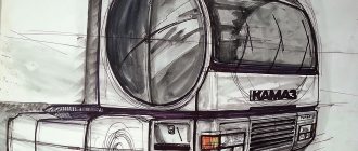
Compared to its predecessors, the appearance of the tractor has changed little. Everything is simple and concise, without frills. The main difference is the headlights, which the developers moved to the front bumper. Their shape has also changed - instead of round ones, the car is equipped with square ones. The sidelights, side lights and turn signals are made in one housing and, together with the fog lights, are located just below.
Features also include a modified bumper grille. Together with new, redesigned doors and powerful wheel arches, it gives the tractor an unusual and at the same time easily recognizable appearance. But, judging by the reviews, the grille is fragile, so for the owner of a KamAZ-6460, tuning begins with it.
The car has a 6x4 wheel arrangement, a powerful engine that allows you to overcome long climbs and confidently overtake even when the body is fully loaded.
The cab of the tractor was changed several times. Initially, no sleeping places were planned, but then one lower bed appeared. The latest development versions have two. The consumer can choose between a single, double or triple version, while not only the driver's, but also the passenger seats have independent air suspension.
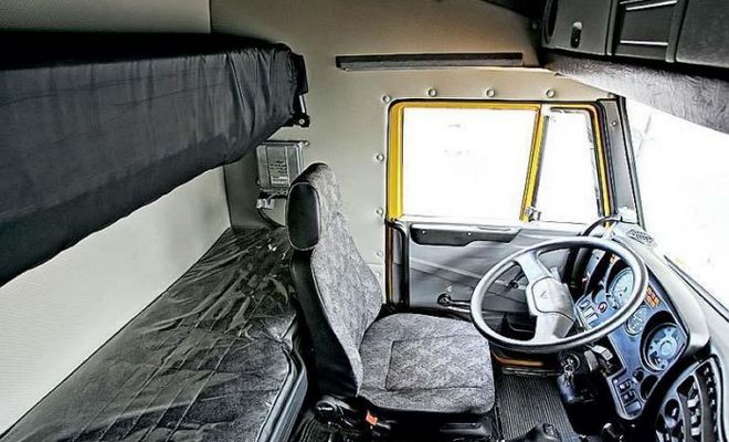
Together with the common aerodynamic cushion on which the cabin is mounted, this makes it possible to go on long trips in comfort. Especially for such trips, the developers offer an ultra-high type cabin. A special bonus of this configuration is the aerodynamic visor mounted above the windshield.
To access the engine, the tractor received a hydraulic lift with an independent drive, saving time when lifting or landing the cab in its place.
contents .. 21 22 ..KamAZ-6460. Electrical equipment
Electrical equipment of cars consists of the following systems: power supply, light signaling, external and internal lighting, instrumentation; heating systems, windshield cleaning and sound alarm systems, engine starting.
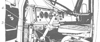
Below are the electrical diagrams of these systems and their descriptions. On the diagrams next to the symbolic image of the elements of electrical equipment, the numbers of the connected wires are shown, the letters indicate their color: B - white: G - blue: Zh - yellow; 3 - green; K - red; KCH - brown; O - orange; P - pink; C - gray; F - purple: H - black.
The power supply system (Fig. 107) serves to power consumers when the engine is running. The sources of electricity are two batteries G2 and G3 connected in series, a generator set G1 connected in parallel with the batteries. The negative terminal of the batteries is connected to the car body through the K17 ground switch with remote control.
The circuit is equipped with relay K16, which breaks the generator excitation winding circuit when the EPI is operating. In addition, when the switch key S21 of the instruments and the starter is in the working position, current is not supplied to the button S6 of the remote ground switch, which prevents accidental switching off of the mass while the engine is running (turning off the batteries is possible only after disconnecting the generator from the electrical system by setting the switch key of the devices and starter to neutral position).
The light signaling system (Fig. 113) is designed to notify drivers of other vehicles about making a turn (turn) or braking, as well as to signal the state of vehicle assembly units that affect traffic safety.
The light signaling system includes: hazard warning lights, braking alarms, turn indicators and indicator lamps for turning on the direction indicators of the vehicle and trailer, indicator lamps for the center differential lock, parking brake system, air pressure drops in the circuits of the pneumatic drive of the brake mechanisms, combined into blocks of indicator lamps, as well as associated switches, switches and relays.
The hazard warning light switch S14 ensures the simultaneous activation of all direction indicators in intermittent mode. At the same time, the control lamp mounted in the switch handle lights up; The turn signal indicator lamps in the indicator lamp unit may not light up. The turn indicators are turned on by combination switch 5 (Fig. 3) with the instrument switch and starter in the operating position. Relay-breaker V3 provides intermittent operation of the direction indicators of the car and semi-trailer; the operation of the indicators is indicated by lamps (separately for the car and semi-trailer) in block H3 of indicator lamps.
The brake signal in the rear lights turns on when the vehicle's braking systems are activated. In this case, the contacts of the brake signal switch S5 close, the intermediate relay K5 is activated and the brake signal lamps of the rear lights light up. The brake signal circuits are included in the power supply circuit, bypassing the instrument and starter switch.
The brake light also turns on when the parking brake system is applied. In this case, the contacts of sensor B12, installed in circuit III of the pneumatic drive of the brake mechanisms, close and the warning lamp lights up. A relay-breaker K2 is installed in the power supply circuit of the parking brake system warning lamp, as a result of which the lamp lights up intermittently. At the same time, through the intermediate relay, the brake signal lamp circuits of the rear lights light up.
The external and internal lighting system (Fig. 111, 112) is designed to ensure vehicle safety, as well as illumination of the driver’s workplace. The external and internal lighting system of a vehicle includes headlights, fog lights, headlights, rear lights, engine compartment lamp, glove compartment and bed lamps, sockets with instrument lighting lamps, cabin lamps, and a portable lamp.
The connection of all consumers to the power source is made according to a single-wire circuit, with the exception of the glove compartment lamp E18, the negative terminal of which is connected to the fuse panel. The low and high beam headlights E5 and E26, fog lights E1 and E25 and side lights are switched on using the combination switch S22 directly from the power source.
The system of control and measuring instruments (Fig. 109) is designed to monitor the operating mode of units and individual assembly units of the vehicle, as well as determine the speed of movement. Instrumentation consists of indicators and sensors. All indicators are installed on the instrument panel in the driver's cabin, sensors are located on the chassis and engine units.
The heating system is designed to maintain optimal temperature conditions in the cabin when the ambient temperature drops. Electric motors M3, M4 (Fig. 110) pump air passing through the cabin heater radiator. When installing electric motors, pay attention to the direction of rotation of their shafts.
The system uses a reversible electric motor ME 250. When the positive pole of the voltage source is connected to the red wire of the electric motor, right rotation is activated, and the negative pole - left rotation.
Electric motors are connected in parallel or in series and can operate in two modes. The mode is controlled using a key switch located in the cabin.
The sound alarm system includes electric and audio signals H9 (Fig. 110), designed to ensure traffic safety, and a relay alarm H2 (buzzer), indicating an emergency drop in pressure in the pneumatic circuits of the vehicle's brake mechanisms, for internal signaling in the cabin.
When the air pressure in the pneumatic system is 392.3...686.5 kPa (4...7 kgf/cm2), the sound should be clear.
Electro-sound signals H9 are located under the cabin and are activated by moving the combination switch handle up; The signals are powered through the intermediate relay K4 installed on the lower instrument panel.
The H2 signal is installed under the instrument panel and is included in the pressure drop signaling circuit in the brake pneumatic drive circuits. The signal is connected to the vehicle ground through a block of warning lamps and air pressure drop sensors; it sounds simultaneously with the lighting of any of the four control lamps, signaling a decrease in air pressure in one of the circuits.
The engine starting system diagram is shown in Fig. 108.
Electrical functional diagrams
Figures 177-186 show functional diagrams of electrical equipment of KAMAZ vehicles.
All diagrams have a single list of elements; The zones where the elements are located relate to the overall electrical circuit of the vehicle.
| Col. | |||
| 5 A | AT 2 | Fuel level sensor SYA MI 407 611-114-01 (or SYA MI 407 611-114-02) TU4573-002-12258598-93 | 1 |
| 5 A | AT 3 | Speedometer sensor 2001.3843 TU37.003.1270-75 | 1 |
| 5 A, 5V, 5V, 1A | B4, B5, B6, B13 | Pressure drop sensor in brake circuits 1, 2, 3, 4 MM 124D-3810600 TU37.003.546-76 | 4 |
| 1A | AT 8 | Oil pressure sensor MM370 TU37.003.387-78 | 1 |
| 1A | AT 9 | Emergency oil pressure sensor MM111 D-3810600 TU37.003.546-76 | 1 |
| 1A | AT 10 | Temperature indicator sensor TM-100A TU37.003.568-77 | 1 |
| 1A | AT 11 | Temperature alarm sensor TM111-08 TU37.003.569-90 | 1 |
| 1A | AT 12 | Parking brake warning lamp sensor MM 124D-3810600 TU37.003.546-76. | 1 |
| 2A | B15 | Temperature alarm sensor TM111-04 TU37.003.5 69-90 | 1 |
| IN 1 | B16 | Tachograph sensor | 1 |
| 5V, 2V | El, E25 | Fog lamp FG152A TU37.003.751-80 | 2 |
| 5V, 2V | E2, E24 | Front direction indicator UP1.3712 TU4573-001-07628635-97 | 2 |
| 5V, 1V | E3, E30 | Side direction indicator 56.3726 TU4573-032-058080936 | 2 |
| 5V, 1V | E4, E23 | Spotlight 2012.3711 TU37.458.043-80 | 2 |
| 5V, 1V | E5, E26 | Headlight 342.3711 TU37.003.1000-80 | 2 |
| 4A, 2A | E7, E20 | Rear lamp 7442.3716-08 TU RB 05882559.010-95 | 2 |
| 4B, 3B | E9, E16 | Marker lamp 26.3712. | 2 |
| 3B | E14, E15 | Cabin light P1.3714010 | 2 |
| 2B | E18 | Glove box lamp PK142B | 1 |
| 2B | E19 | Sleeper lamp PK142B | 1 |
| 2A | E21, E22 | Torch pin candle 1102.3740 | 2 |
| 2B | E27 | Engine compartment lamp PD308-B-0 TU37.003.187-80 | 1 |
| 3A | E28 | Spotlight (work area lighting) 2012.3711 TU37.458.043-80 | 1 |
| 4A | E34.E35 | License plate light FP131-AB | 2 |
| 2B | F1 | Fuse block 111.3722 TU37.003.754-76 | 1 |
| 3A | F2, F3 | Fuse block PR112 TU37.003.775-76 | 2 |
| 3A | F4 | Fuse PR119-01 TU37.003.731-76 | 1 |
| 1B | G1 | Generator 3122.3771 (2 kW) TU37.463.155-88 | 1 |
| 1A | G1 | Generator G273V (800 W) TU37.003.790-77 | 1 |
| 1A | G2, G3 | Battery 6ST-190A TU 16-729.384-83 | 2 |
| 3B | H1 | Brake system warning lamp block 2312.3803010-23 TU37.003.1109-92 | 1 |
| 3B | H2 | Alarm relay 733.3747-10 TU37.003.709-80 | 1 |
| 4B | H3 | Control lamp block 2312.3803010-24 TU37.003.1109-92 | 1 |
| 4A | H4 | Control lamp for turning on the center differential lock 2212.3803-14 TU37.003.1109-92 | 1 |
| 4A | H6 | Downshift control lamp 2212.3803-46 | 1 |
| TU37.003.1109-92 | |||
| 4A | H6 | Control lamp KOM 2212.3803-15 TU37.003.1109-92 | 1 |
| 2B | H9 | Signal set S306D-01/S307D-01 TU37.003.533-79 | 1 |
| 1B | H14 | Indicator lamp for high beam headlights 2212.3803-28 TU37.003.1109-92 | 1 |
| 4A | H17 | Air filter clogging indicator lamp 2212.3803-20 TU37.003.1109-92 | 1 |
| 4A | H18 | Range control lamp 2212.3803-35 TU37.003.1109-92 | 1 |
| 5V | K1 | Starter relay 738.3747-20 TU37.469.023-97 | 1 |
| 3B | K2 | Handbrake warning lamp breaker RS493 TU37.003.588-77 TU37.003.1010-80 | 1 |
| 3A | K3 | Heater motor relay 901.3747 TU37.003.1418-94 | 1 |
| 3B | K4 | Sound signal relay 901.3747 TU37.003.1418-94 | 1 |
| 3B | K5 | Brake signal relay 901.3747 TUZ7.003.1418-94 | 1 |
| 3B | KB | Relay for additional headlights 901.3747 TUZ7.003.1418-94 | 1 |
| 3B | K7 | Fog lamp relay 901.3747 TU37.003.1418-94 | 1 |
| 2B | K8 | Thermal relay for electric torch device 1202.3741 TU37.003.711-79 | 1 |
| 2A | K9 | Low beam relay 901.3747 TU37.003.1418-94 | 1 |
| 2A | K10 | High beam relay 901.3747 TU37.003.1418-94 | 1 |
| 2A | K12 | EFU switching relay 901.3747 TU37.003.1418-94 | 1 |
| 2A | K13 | Engine stop relay 738.3747-20 TU37.469.023-97 | 1 |
| 2A | K14 | Rear fog lamp relay 901.3747 TU 37 003.1418-94 | 1 |
| K15 | Relay KOM 901.3747 TU 37.003.1418-94 | 1 | |
| 1A | K16 | Relay for disconnecting the generator excitation winding 901.3747 TU37.003.1418-94 | 1 |
| 1A | K17 | Battery switch 1400.3737 TU37.003.574-74 | 1 |
| 3A | K18 | Windshield wiper relay 3502.3777 TU37.104.222-2001 | 1 |
| 5A | M1 | Starter 5662.3708-10 TU37.451.041-94 | 1 |
| 5V | M2 | Window washer 1112.5208-01 TU37.003.639-87 | 1 |
| 3B, 2A | M3, M4 | Heater electric motor ME250 TU37.003.789-76 | 2 |
| 2B | M5 | Windshield wiper 271.5205 | 1 |
| 5V, 5A | M14, M15 | Electric drive for headlight range control EPK06 | 2 |
| 4B | P1 | Tachometer 3631.3813 TU37.003.1251-85 | 1 |
| 4B | P2 | Indicating device 1211.3802 TU37.003.691 -81 | 1 |
| 3B | P3 | Pressure indicator 1908.3830 | 1 |
| 3B | P4 | Instrument cluster 28.3801 TU37.003.670-75 | 1 |
| 1B | P12 | Tachograph 1318.270000 0025 23 TU 4573-001-43820854-97 | 1 |
| 3B | R1 | Instrument panel light switch with rheostat VK416-B-01 TUZ 7.003.1174-83 | 1 |
| 5A | S1 | Reversing light switch VK403B TU37.003.108-76 | 1 |
| 5A | S1 | Reversing light switch | 1 |
| 5A | S2, S3 | Switch k.l. interwheel differential lock VK403B TU37.003.188-76 | 2 |
| 5A | S4 | Switch k.l. center differential lock VK403B TU37.003.108-76 | 1 |
| 5V | S5 | Brake light switch 15.3720 | 1 |
| TU37.003.1159-83 | |||
| 5V | S6 | Remote power switch button 11.3704-01 TU37.003.710-80 | 1 |
| 5V | S7 | Central light switch 581.3710-01 TU37.003.1211-86 | 1 |
| 5V | S8 | Additional headlight switch 3842.3710-02.06 TU37.003.1222-82 | 1 |
| 5V | S9 | Fog light switch 3842.3710-02.03 TU37.003.1222-82 | 1 |
| 4B | S40, S31 | Lamp switch 3842.3710-02.09 TU37.003.1222-82 | 2 |
| 5V | S11 | Rear fog lamp switch 3842.3710-05.04 TU37.003.1222-82 | 1 |
| 5A | S13 | Switch k.l. reduction gear VK403B TU37.003.188-76 | 1 |
| 4B | S14 | Hazard warning light switch 32.3710 TUZ 7.003.1106-82 | 1 |
| 4B | S15 | Button for switching on spark plugs for electric torch device 11.3704-01 TUZ 7.003.710-80 | 1 |
| 3A | S17 | Cross-axle differential lock switch VK343-01.14 TU 37.003.701-75 | 1 |
| 3A | S18 | Power take-off switch P602 TU37.467.525-77 | 1 |
| 4B | S20 | Windshield wiper switch with washer 4002.3709 TU37.003.1335-87 | 1 |
| 4B | S21 | Instrument and starter switch 2621-3704 TU3. TsT-1.051-94 | 1 |
| 4B | S22 | Switch for direction indicators, low and high beam 6602.3709 TU37.003.1336-87 | 1 |
| 4B | S23 | Heater electric motor switch P147-04.11 TU37.003.701-75 | 1 |
| 3B | S24 | Switch for raising and lowering the platform P147-06.15 TU37.003.701-75 | 1 |
| 1A | S52 | Neutral switch | 1 |
| 5A | S53 | PTO switch | 1 |
| 5A | S54 | Range switch | 1 |
| S55 | Power button KOM 11.3704-01 TU37.003.710-80 | 1 | |
| S56 | Switch KOM 3812.3710-02.30 TU37.003.1222-82 | 1 | |
| 3A | V1, V6 | Diode with protective housing 3403.3747 TU37.003.953-79 | 2 |
| 2B | V3 | Turn signal breaker RS951A2 TU37.453.056-82 TUZ7.003.990-80 | 1 |
| 4A | V8 | Headlight range control unit BUK29 TU4573-047-07530936-00 | 1 |
| V9, V10 | Vehicle on-board network protection unit BZS-2.321.3722 TU4573-001-26002172-96 | 2 | |
| 5B, 5B, 2A, 2B, 1B, 1B, 4B, 2B, 1B, 5B, 1B , 2A, 2B, 2B, 1B | X1, X7, X15, X16, X19, X23, X28, X29, X48, X60, X61, X62, X64, X65, X66 | Single-pin connector | 15 |
| 5B, 5B, 5B, 1B, 1B, 1B | X2, X4, X5, X20, X21, X22 | Six-pin connector | 6 |
| 5B, 4B, 4B, 3B, 3A, 4A, 4A, 4A | X3, X10, X11, X12, X41, X44, X45, X48. | Two-pin connector | 8 |
| 5B, 5A, 5A, 1A, 5A | X25, X26, X38, X42, X63 | Four-pin connector | 5 |
| 5V | X31 | Portable lamp socket 47K TU16-526.359-74 | 1 |
| 5A | X35 | External trigger socket PS315-3723100 TU37.003.229-79 | 1 |
| 3A | Y1 | Electromagnetic valve for cross-axle differential locking KEB420 TU 1-5540036-93 | 1 |
| 1A | Y2 | Fuel solenoid valve 1102.3741 TU37.003.740-79 | 1 |
| 1A | Y4 | Solenoid valve for power take-off KEB420 TU1-5540036-93 | 1 |
| 1A | Y5 | Electromagnetic valve for raising and lowering the platform KEB420 TU1-5540036-93 | 1 |
| 1A | Y6 | Electromagnetic valve for lowering the platform KEB420 TU1-5540036-93 | 1 |
| 2A | Y10 | Engine stop electromagnetic valve EM 17 TU3742-006-34013480-00 | 1 |
Rice. 107. Functional diagram of power supply with an 800 W and 2 kW generator with a built-in integrated voltage regulator.
The circuit has two options for the instrument switch and starter.
Rice. 108. Functional diagram of engine starting. The circuit has two options for the instrument switch and starter.
Rice. 109. Functional diagram of control and measuring instruments.
The circuit has an option for vehicles with two fuel tanks.
Rice. 110. Functional diagram of windshield wipers, heating and sound alarm.
Rice. 111. Functional diagram of interior lighting.
Rns. 112. Functional diagram of outdoor lighting.
Rns. 113. Functional diagram of external light signaling and wheel locking.
Rice. 114. Functional diagram of light and sound signaling of the brake system.
contents .. 21 22 ..
Specifications
Despite the common name - KamAZ-6460 truck tractor - the technical characteristics of the modifications have different engine power and load capacity, the models are equipped with different tire sizes, and additional equipment may be offered to perform special tasks.
The parameters of KamAZ-6460-63 stand out from other models in the series due to its additional hydraulic system and powerful diesel engine, which is called KamAZ-740.63-400. The presence of a power take-off allows the use of trailers with the tractor that require additional capabilities from the main vehicle, for example, dump bodies, tank trucks for transporting liquids, etc.
KamAZ-6460-73 received a reinforced engine that meets Euro-4 standards, a new fifth-wheel suspension with a possible load of up to 16 tons. At the customer’s request, individual assemblies are equipped with additional casings over the fuel tanks, allowing them to transport tanks with petroleum products.
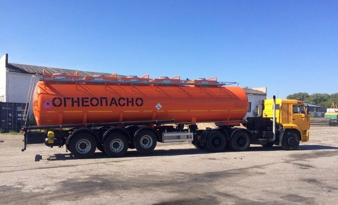
Overview of vehicle dimensions and load capacity:
- length - 6.5 m;
- width - 2.5 m;
- height - 3.83 m (extra high cabin).
The curb weight of the vehicle is 9.35 tons, the gross weight is 26 tons, of which 6 tons are on the front axle, 20 tons on the rear axle, while the load on the “saddle” is no more than 16 tons.
Power unit
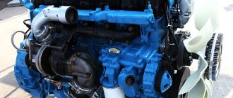
Engine power depends on the configuration. In the first versions it is 360 hp. With. The latest modifications have up to 400 hp. With. The cost of this is that the engine is sensitive to fuel quality. Both options meet environmental standards Euro-3 (the latter - Euro-4), have 8 cylinders with a V-shaped arrangement. Engine capacity - 12 liters. Turbocharging and pre-heating are included.
Despite the powerful engine, the KamAZ-6460 consumes fuel economically.
Costs per 100 km of travel do not exceed 27 liters, but in the case of poor road conditions and heavy loads, consumption can double.
If, when driving with a load, you constantly push the maximum speed (~95 km/h), then the consumption can reach 60 liters. The basic configuration has 2 tanks of 300 liters each.
Versions for export to European countries have improved characteristics, including a reduction in fuel consumption by 10% or more, as well as an increased service interval and Euro 5 and 6 environmental standards.
One of the distinctive features of the imported Cummins L360 power unit is the mechanical fuel control system.
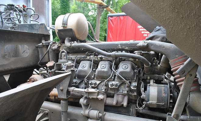
This method provided several advantages:
- lack of electronic control of the high pressure fuel pump;
- increasing the operating time between maintenance;
- simplification of design;
- trouble-free engine starting in winter;
- unpretentiousness in terms of fuel quality.
This power plant is equipped with tractors designed for international freight transportation.
Transmission
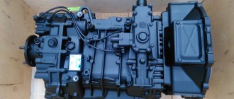
The main difference from other models of the plant was the gearbox. The plant orders German ZF specifically for this tractor. It has 16 stages and a single-disc clutch with pneumatic booster. Starting with model 63, cars receive locking center and cross-axle differentials.
Suspension
There are no innovations in this area. The car has a dependent spring suspension, the design of which completely replicates the options for other models of the plant.
Brake system
The tractor received standard drum-type brake mechanisms, the diameter of the drums was 420 mm. Smooth and safe stopping is ensured by ABS - anti-lock braking system.
Spare parts for KamAZ-6460 trucks (Euro 4)
The Kama Automobile Plant began producing KamAZ-6460 cars in 2003. The truck has a 6x4 wheel arrangement. KamAZ-6460 was widely used for constant work with a trailer and transportation of various cargoes, such as sand, crushed stone and other various bulk materials. KamAZ-6540 has a clutch that has excellent controllability on all kinds of roads. Complies with Euro-4 environmental standard.
KamAZ-6460 has a body with a metal platform that allows you to open the side and rear sides. The all-metal cabin is located above the engine and is designed with two berths with a high (or in some trim levels with an extra-high) roof. The gearbox is manual, 16-speed. It has a KamAZ-54115 platform with a rear layout. Thanks to our KamAZ-6460 spare parts catalog, you can easily find all the spare parts you need, because using the catalog is easy and convenient.
Gross semi-trailer weight, kg: 36500 Gross train weight, kg: 46000 Fifth wheel load, kg: 16500 Curb vehicle weight, kg: 9350 Engine: diesel turbocharged, with intercooled charge air KamAZ-740.63-400 (Euro- 3) Power kW (hp): 294(400) Arrangement and number of cylinders: V-shaped, 8 Cylinder displacement, l: 11.76 Maximum speed, km/h: 85
On the website you can buy spare parts for KamAZ-6460 in a special catalog. Our specialists will advise you on all questions and tell you about all the KamAZ-6460 spare parts that are right for you. By purchasing spare parts from Dynamics 76, you are guaranteed to purchase high-quality parts for KamAZ.
Advantages and disadvantages
The positive features of KamAZ-6460 include:
- the presence of air suspension not only in the driver’s seat;
- German checkpoint;
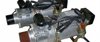
- good autonomous cabin heater;
- high ground clearance;
- high load capacity;
- wide choice of modifications;
- optimal dynamic performance.
There are also disadvantages. The main thing is called the spring suspension of the rear part, while analogues have long used pneumatics. Other disadvantages:
- small tank, not expandable;
- lack of engine choice (American is available only on export versions);
- whimsical to fuel quality;
- insufficient cabin build quality and low comfort.
Price
The price of the new KamAZ-6460 according to the manufacturer’s price lists starts from 3 million rubles. At the same time, the price of purchasing and renting a used model does not differ much from the factory one and largely depends on the year of manufacture. A car with low mileage and one that came off the assembly line less than 5 years ago may cost slightly less than a new one. Older cars - the first years of production - can cost less than 1 million.
When considering renting, you need to take into account that the tractor needs a trailer. Modifications differ in their characteristics and options. You can find prices of 1500-2000 rubles. per hour of work.
