Crane beam device
A beam crane is a technical device designed to lift and move cargo. According to the description given in the Brief Polytechnic Dictionary, a beam crane is a lightweight single-girder overhead crane with a manual or electric drive. A distinctive feature of the device is the presence of two support points, and not one, like most other lifting mechanisms. The crane beam supports can be fixed, rigidly fixed structures, or movable supports made like bridge supports. Most often these are rolled metal products mounted on the load-bearing walls of the room in which the mechanism is located.
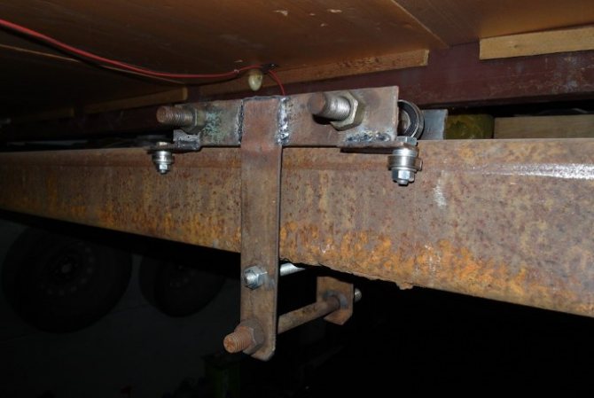
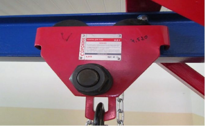
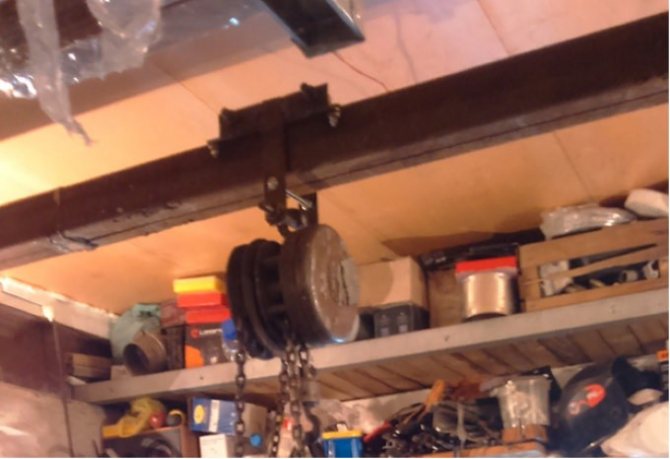
One of the supports of a homemade crane beam, made of two corners welded together, attached to the wall of the garage.
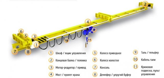
The crane beam consists of: load-bearing supports, the working beam itself, a slide for moving along the supports, a movable carriage, any lifting mechanism with a rotating hook (hoist, winch, hoist).
Registration of crane beams
Question:
Is it necessary to register a beam crane (with a lifting capacity of up to 10 tons) as a hazardous production facility in the RTN if it is installed on a foundation. According to information from the design organization, if the crane-beam is installed on a slab base, then it is not necessary to register, but if it is installed on a foundation base, then it is necessary. Can you explain?
Answer:
According to clause 1. Art.2. Federal Law “On Industrial Safety of Hazardous Production Facilities” N 116-FZ dated July 21, 1997 (with all amendments and additions):
“Hazardous production facilities in accordance with this Federal Law are enterprises or their workshops, sites, sites, as well as other production facilities specified in Appendix 1 to this Federal Law.”
The category of hazardous production facilities includes facilities where:
...permanently installed lifting mechanisms are used (with the exception of elevators, lifting platforms for the disabled), escalators in subways, cable cars, funiculars; ... See paragraph 3. Appendix 1 Federal Law-116 (as amended by Federal Law No. 22-FZ dated March 4, 2013).
Federal norms and rules in the field of industrial safety “Safety rules for hazardous production facilities where lifting structures are used” (as amended by Rostechnadzor Order N 146 dated April 12, 2016), further FNP PS establish the necessary requirements for:
- activities in the field of industrial safety at hazardous production facilities (hereinafter referred to as HIFs), which use permanently installed lifting mechanisms (hereinafter referred to as lifting structures), including employees of these HIFs.
According to clause 3. FNP PS: “The requirements of these FNP apply to ensuring the industrial safety of hazardous production facilities where the following lifting structures (hereinafter referred to as the PS, when it comes to the lifting structures listed in this paragraph) and equipment used in conjunction with the PS are used:
- a) lifting cranes of all types;
- b) overhead stacker cranes;
- c) pipe-laying cranes;
- d) cranes;
- e) construction hoists;
- f) lifts and towers designed to move people;
- g) electric freight trolleys moving along elevated rail tracks together with a control cabin;
- h) electric hoists;
- i) excavator cranes designed only to operate with a hook suspended on a rope or an electromagnet;
- j) replaceable load-handling devices (hooks, grabs, magnets) and removable load-handling devices (traverses, grabs, grabs, slings), used in conjunction with cranes for lifting and moving loads;
- k) containers for transporting goods classified as dangerous, with the exception of special containers used in metallurgical production (ladles, molds), as well as special containers used in sea and river ports;
- m) special removable cabins and cradles, hung on the load-handling parts of cranes and used for lifting and moving people;
- m) rail tracks (for supporting and suspended substations) moving on rails.”
In accordance with paragraph 146. FNP PS: “Only those hazardous production facilities where substations are operated are subject to registration, subject to registration with the bodies of the Federal Service for Environmental, Technological and Nuclear Supervision and other federal executive authorities in the field of industrial safety, which in the prescribed manner are granted the right to register subordinate facilities in the state register of hazardous production facilities (hereinafter
- federal executive authorities in the field of industrial safety, maintaining the register of hazardous production facilities).
“The following PS are not subject to registration with the Federal Service for Environmental, Technological and Nuclear Supervision:
- a) overhead cranes and jib cranes with a lifting capacity of up to 10 tons inclusive, controlled from the floor by means of a push-button device suspended on the crane, or from a stationary remote control, as well as remotely controlled via a radio channel or a single-wire communication line;
- b) jib-type cranes with a lifting capacity of up to 1 ton inclusive;
- c) jib-type cranes with a constant reach or not equipped with a slewing mechanism;
- d) adjustable cranes for the installation of masts, towers, pipes, installed on the structure being erected;
- e) PS used for educational purposes at training grounds of educational institutions;
- f) cranes installed on excavators, crushing and reloading units, spreaders and other technological machines, used only for the repair of these machines;
- g) electric hoists with a lifting capacity of up to 10 tons inclusive, used as independent substations;
- h) loader cranes installed on the foundation, loader cranes with a lifting capacity of up to 1 t and with a load moment of up to 4 t m inclusive;
- i) cargo construction hoists;
- j) rail tracks, replaceable load-handling devices, removable load-handling devices and containers;
- l) overhead stacker cranes;
- m) pipe-laying cranes.”
See paragraph 148. FNP PS.
It should be noted that there are various foundation foundations on which the beam crane rests, which are calculated for the load-bearing capacity for each type of overhead crane, but are not a criterion for registering the substation with Rostechnadzor.
Thus, if we are talking about a crane beam with a lifting capacity of up to 10 tons, controlled from the floor by means of a push-button device suspended on the crane, or from a stationary remote control or controlled remotely via a radio channel or a single-wire communication line, and registration of the substation as part of the hazardous production organization in the Rostechnadzor authorities with registration in the Register of Hazardous Production Facilities is not required.
Tools and materials
To create this mechanism in the garage, you will need the following tools and materials.
- Rolled metal – angle, channel, I-beam.
- Bearings of different sizes.
- Welding machine with electrodes.
- "Bulgarian".
- Drill or drilling machine.
- Actuating mechanism – hoist, hoist.
- Marking tool (ruler or caliper, tape measure, chalk or marker)
- Bolts, washers, nuts.
The length of the rolled metal is selected based on the size of the room, and its grade is determined from the calculations given below. Bearings can be taken in any suitable size. The quantity is selected according to the principle: 4 pcs. for one slide, 4 pcs. – for the second, plus 4 pcs. for the carriage (lift body). Total: 12 pieces. The bearings for the slide must be the same size; the carriage can be fitted with bearings of the same size or one size larger or smaller. Bolts for fastening must be selected with large metric threads. The actuator is selected according to its maximum load capacity and design loads.
Carrying out calculations
In order to make a crane beam in the garage with your own hands, you need to calculate the dimensions of the structure and the grade of rolled metal according to the load capacity. Such calculations are performed using special online calculators, which allow you to select the necessary materials with sufficient accuracy for handicraft production. These calculators require you to enter the dimensions of the structure and the maximum allowable weight that is expected to be lifted and moved. Then you need to make a working drawing and you can start working.
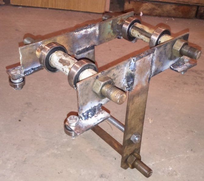
It is best to make the working beam of the mechanism from equal-flange I-roll, because when using welded corners it is very difficult to achieve uniformity of the rolling surface. Uneven rolling surfaces will lead to underloading of some bearings and overloading of others. The working beam slide can be made from a section of channel, the length of which will be equal to the width of the I-beam flange of the working beam. The size should allow it to slide freely along the span beam supports.
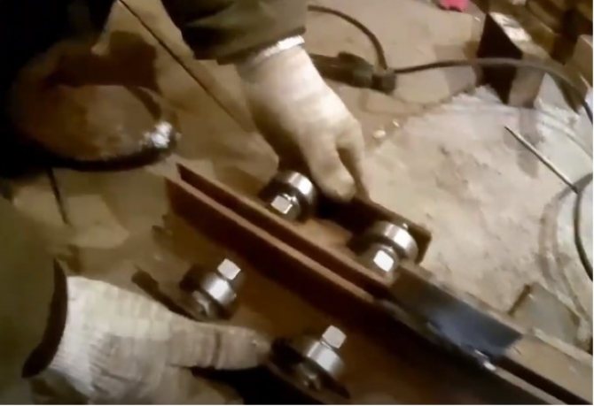
Here the bolts are used as racks for fastening the support bearings.
Drive types
There are 2 types of drives installed on the crane beams: manual and electric.
Manual variety
This type is suitable for handling loads that are light in weight. The movement speed of this type of device is lower than that of those made with an electric mechanism. In them, the working tool is represented by worm-driven mobile hoists
The drive is made up of a shaft, which is combined with running wheels. The transmission is connected to the traction wheel using a chain.
Electric drive is more common. To move cargo, it uses a winch or hoist, which are mounted on special trolleys.
The mechanism is activated by:
- gearbox;
- trolley wheels;
- electric motor.
Basic device parameters
The main parameter that distinguishes a beam crane is the weight of the load being lifted. In addition, the following features are highlighted:
- The load capacity of this mechanism depends on the type of its design. For support beams this value is 1-10 tons.
- Suspended structures have a smaller value, not exceeding four to five tons.
- The speed of the mechanism may vary.
Read also: What kind of oil is poured into the rokhlya
Hanging devices are somewhat slower. Their speed does not exceed 0.5 meters per second. In the description of this mechanism, data on the span size must also always be indicated. For this type of device, it ranges from 3 to 28 meters (sometimes 28.5). The span is supposed to be the area (space) that the device can serve.
This parameter can be divided into 2 categories:
- with one span (these devices are characterized by a length from 3 to 15 meters);
- with two spans (these devices correspond to a length from 7 to 12 meters).
Using suspended types of beam cranes, loads can be lifted to a height of 6-36 meters. For supporting types of crane beams, this value is lower and reaches 6–18 meters.
Metal variety
These beams are usually made in the shape of a rectangular box by welding four steel sheets.
Often, lattice trusses or bent sheets are used for its manufacture. This is done in order to increase the structure’s resistance to bending under the influence of significant weight loads.
The wall of the bridge, located in the body, is supporting. Consequently, the outer wall acts as an auxiliary one.
to make the auxiliary wall . Thanks to this solution, the weight of the entire structure is reduced. The cuts are made in such a way that the load-bearing capacity of the structure is not reduced.
Single and double beam varieties
Metal types of crane designs most often have frames with a double-girder device.
A single beam crane is also found in this type of device. It is usually made from an I-beam with a triangular or rectangular cross-section and, as in the case described above, is made in the form of a truss or sheet. Diaphragms are welded inside the main beams to strengthen the structure.
They are located at an angle of 90 degrees to the bearing axis of the beam. Their length is almost identical to the height of the walls. With a large length of the main beams, there were often situations where they sagged inward due to their inability to withstand the impressive weight of the loads being moved. To eliminate this drawback, the beams are first bent upward, thus forming the so-called construction rise.
the end beams is similar to rectangular boxes. Axle boxes and crane movement limiters are installed on them. In devices that are operated outdoors, additional anti-theft systems are placed inside the end beams. They protect the process of movement under the influence of strong winds.
The operation of this kind of mechanisms in construction and other areas greatly simplifies the performance of many works. And in some cases, using them at work is the only possible way to move or lift loads. This is why their prevalence is so high.
Lift carriage
The lift carriage is made from a section of channel, the length of which is equal to the length of the supporting part of this mechanism. The size of the channel is assumed to be equal to the width of the I-beam flange.
It is necessary to clarify that during the manufacture of the carriage, the support bearings on different sides of the carriage are not installed opposite each other, but “in a running motion.” This was done in order to distribute the load on the I-beam shelf as evenly as possible.
The carriage can be made from two metal plates of any shape - triangular, square, truncated cone. Support bearings are installed on the inner sides of both plates, and underneath the plates are combined into a single unit using bolts or welding. In the lower part, a rod or insert is installed between the plates, to which the fastening hook of the actuator clings. This type is used when using lifting devices that are attached to the lift body with a hook.
If it is envisaged that the lift will be fastened using a support plate, then instead of a bolt, a plate with holes for mounting bolts is attached under the hook. They fix the actuator on the carriage. For some types of carriages, especially for industrial use, an additional motor is mounted on the support platform, which, by rotating the support bearings, moves the lift body along the working beam. As a rule, an electric motor with a low speed is installed as such a motor, the power to which is supplied by a flexible cable on sliding suspensions. In conditions of handicraft production, when the crane beam is used infrequently and the volume of work is small, the installation of such a complex structure is hardly justified.
The self-propelled carriage is controlled using a multipolar switch, which further complicates the design. In a garage, when making a crane beam yourself, a simple non-self-propelled carriage, which moves along the beam manually using a drive cable or chain, is quite sufficient.
Some craftsmen make female lift bodies that are installed on the top flange of the I-beam, rather than on the bottom. In this case, the support bearings are installed inside the lift body, and the lift itself is assembled from two identical parts. The device becomes more voluminous, but its reliability increases. For better sliding along the beam, additional bearings are installed horizontally on the lift body, two on each side. This is done so that the lift body does not touch the plane of the beam.
Here the lifting mechanism is fastened with a fastening hook using the lowest bolt.
A homemade lift body designed to use a lifting device attached with a mounting hook to the bottom plate.
Assortment and main characteristics
There are two main types of lifting equipment: single-girder and double-girder crane beams. She may be:
- Supporting (the structure is installed on stationary supports).
- Suspended (the device is attached using a suspension to a path, for example, load-bearing beams of a building).
Supporting devices are considered more reliable, but suspended ones are more mobile and easier to install. The overhead crane can be manual or electric, controlled from the floor or remotely using a remote control. In the catalog, the suspended crane is presented in versions with one or two spans.
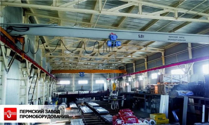
Single-beam electric overhead cranes, both suspended and support, are produced for air temperatures from -20 degrees Celsius to +40 (in a special version from -40 degrees Celsius). At the same time, support cranes have a lifting capacity of up to 16 tons with spans of up to 28.5 m, a height of up to 100 m, while the lifting capacity of overhead cranes is up to 12.5 tons (up to 10 in a two-span version) with spans up to 15 m (up to 30 in a two-span version ).
Installation of lifting mechanism
After assembling the lift body and its trial installation on the beam, it is removed again, and holes are drilled according to the size of the factory holes in the mechanism platform. The lifting mechanism is installed on the carriage, then the assembled device is installed on the working beam. Installation of a lifting device with a mounting hook is even simpler: it is simply hooked with the hook onto the carriage that is fully assembled and installed on the beam supports.
Crane beam assembly
The assembly of a homemade crane beam occurs as follows:
- the device supports are attached to the wall or ceiling;
- a carriage is installed on the prepared working beam;
- if the actuator is mounted on a support platform, then it is installed on the lift body;
- the assembled work beam is lifted and placed on supports;
- check smooth operation and adjust operating parameters.
In the case of attaching the lifting mechanism to the support platform, the assembly is complete.
An assembled crane beam with a lift, which is fixed with a fastening hook by the lower bolt.
Making a simple lifting device yourself in your garage is not that difficult. It is necessary to carry out the calculations correctly and boldly get to work. At the same time, you need to remember about safety precautions - any lifting device is potentially dangerous. For example, according to the existing requirements of Rostechnadzor, the presence of more than 30% broken threads in a steel rope (cable) makes such a cable unsuitable for further use.
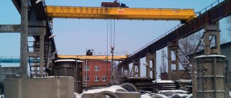
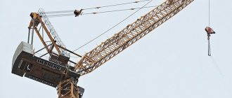
Overhead crane
An overhead crane has a clear definition according to GOST ISO 4306-1:2007. In accordance with the state standard, a crane is equipment with lifting elements for carrying loads over various distances. It is a steel platform that is perpendicularly attached to the bridge and moves along suspended or support-type crane tracks. The standard equipment for bridge equipment includes:
- Crane trolley with 1 or 2 lifting mechanisms;
- Cable or trolley conductors;
- Control unit (radio remote control or operator's cabin).
Very often it has two supporting platforms. Depending on the type of cargo, there are hook, grab, cast, magnetic and other types of grip units.
Read also: How to cook thin stainless steel with argon
Separately, it is worth noting the load-carrying capacity of a full-fledged mechanism. The range available to bridge engineering ranges from 3-1000 tons depending on the characteristics of the structure. Can move at a speed of 10 m/sec.
Installing a bridge device is quite labor-intensive and requires special equipment. Possible options:
- Fastening the beam under the movable base;
- Fastening the beam to a movable base.
The main advantage of the bridge structure is high speed of operation, good load capacity, large working area, mobility of the crane trolley, work with explosive and magnetic loads.