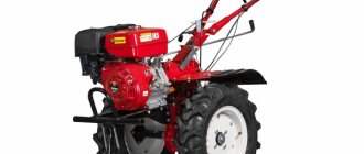
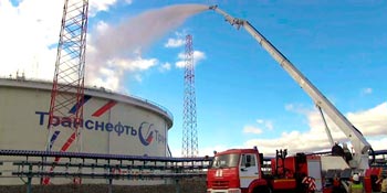
Fireman's car lift is a special fire truck equipped with special stationary superstructures in the form of rotary cranked, telescopic boom devices with a cradle on top.
Fireman's articulated car lift
Saving people and property during fires is the most important type of firefighting action. Their main methods are the movement of people and property, including ascent or descent using special technical means to a safe place and protecting them from fire hazards.
When carrying out these actions, non-mechanized and mechanized means are used. The first include stationary and manual (portable) fire escapes, various rescue devices (rescue hoses, ropes, etc.), inflatable and shock-absorbing devices, etc. The second category includes fire-fighting ladders (AL) and fire-fighting aerial lifts.
Fire trucks are mobile rescue equipment: they are used by fire and rescue units of fire and rescue garrisons.
Fire trucks have greater maneuverability than ladders, but lack such an important advantage of the ladder as the ability to continuously evacuate people without changing the position of the boom. At the same time, they have broader capabilities compared to ladder trucks for supplying water to heights, as well as for carrying out evacuation simultaneously from several positions (windows, balconies, different floors).
The load capacity of the chassis and the dimensions of the fire trucks must be such that their maneuverability in urban areas is not limited, and it is possible to install and maneuver fire trucks and fire trucks near objects near which there are no asphalt concrete surfaces. Therefore, they are built on highly cross-country chassis with a 6×6 or 6×4 wheel arrangement (depending on weight) with engines that ensure their operation in transport and stationary modes.
Fire trucks are designed for installation on sites with a slope of no more than 3° and can be safely used at wind speeds in any direction of no more than 10 m/s.
On this topic ▼
Firefighting foam lifters
Types, device and performance characteristics
Control panels for firefighting vehicle lifts are located on the platform and in the cradle, if it is provided for in the design. Firefighting ladders and vehicle lifts are equipped with automation and alarm systems that allow monitoring and adjusting parameters that affect the safety of their operation.
Among the foreign models of firefighting aerial lifts in our country, 30-meter articulated aerial aerial lifts Bronto Skylift 303 on a KamAZ-53213 or Isuzu LV136 chassis, as well as aerial lifts with an articulated-telescopic boom type Bronto Skylift F52HDT and F54HDT on a Scania chassis with a maximum lifting height of 52, respectively, are widespread in our country. and 54 meters.
The carrying capacity of the cradles of 50-meter car lifts reaches 400 kg with a maximum boom reach of 21 meters. On the right side of the boom along its entire length there is a telescopic ladder, consisting of 5 main and one end bends. The maximum load of the lift boom is 8 people (7 people on the ladder and 1 person in the cradle).
Purpose
Firefighting lifts are designed for:
- delivery of personnel and fire-technical equipment (FTE) to the fire site;
- lifting personnel, anti-tank equipment and equipment to heights;
- ensuring the implementation of rescue and rescue operations (ASR) at height;
- supply of fire extinguishing agents to extinguish fires at height.
Kinds
Fire trucks are:
- cranked (APK) - with articulated joints of the knees;
- telescopic (TPL) – with a telescopic connection of the knees;
- articulated-telescopic - with an articulated-telescopic connection of the knees.
A fire-fighting articulated auto-lift (APK) is a special fire-fighting vehicle equipped with a stationary mechanized rotary articulated and (or) telescopic lifting boom, the last link of which ends with a platform or cradle, designed for carrying out rescue operations at heights, supplying fire extinguishing agents at heights and possible use as a load-lifting crane with a folded set of elbows.
Firefighter telescopic ladder lift (TPL) is a special firefighting vehicle equipped with a stationary mechanized rotary cranked-telescopic boom (pack of knees), the last link of which ends with a cradle, and has a flight of stairs located on the side of the boom, designed for rescue operations and fire extinguishing in multi-storey buildings, as well as for other auxiliary operations.
Additional Description
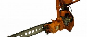
Experienced managers of companies specializing in repairs know very well how little effect manual movement of oversized materials up stairs has and how dangerous it is. This method leads to damage to the plaster and paint of staircases. In addition, such work greatly tires workers, which reduces labor productivity and creates a high risk of work-related injuries.
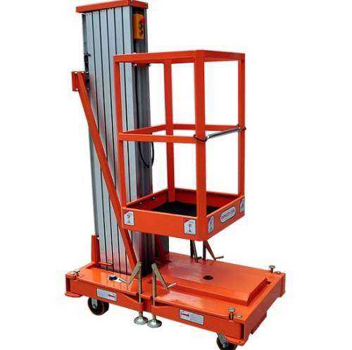
proposes in this case to abandon manual labor and use an excellent alternative - a mast lift . This equipment allows you to make work more efficient, save on labor costs, avoid problems with workers, and reduce the time required to complete work. PMG mast lifts move loads vertically, which is necessary when carrying out repair work, as well as for lifting various products.
The basis of this type of lift is a supporting mast or console. They can be vertical or inclined. Vertical lifts are designed on one or two masts. There are two installation options:
- on surface,
- on the pit.
The cargo mast lift can lift cargo to a height of up to 40 meters. The weight of the cargo should not exceed 2 tons.
Designers and manufacturers took a responsible approach to the issue of safe operation of mast lifts . The structure is equipped with a number of devices to ensure safe vertical movement of loads. Among them it is worth noting:
- sudden braking catcher, which allows you to hold the loading platform in the event of a break in the traction rope,
- devices protecting against rope loosening and overload,
- blocking platform railings.
Mast lifts can be installed inside and outside the building.
If your company plans to increase the efficiency and speed of work, then you need to do everything possible to automate it as much as possible. And here a cargo cantilever lift will become an indispensable assistant. We will produce for you a high-quality and durable lift that meets all the stated requirements.
Device
All types of firefighting vehicle lifts (see above) have the same design:

Types of firefighting vehicle lifts
1 – chassis; 2 – supports; 3 – spring locking mechanism; 4 – rotating frame; 5 – knee lift mechanism; 6 – set of knees; 7 – cradle
a – with articulated knees; b – with telescopic knee connection; c – with articulated-telescopic knee joint
In the future, the option with a telescopic connection of the knees will be considered.
The booms and cradle are controlled by hydraulic cylinders.
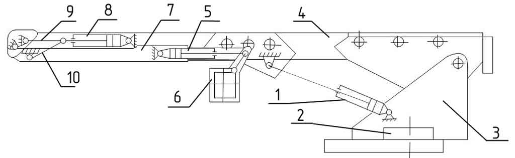
Basic kinematic diagram of lifting and extending the cradle
1 – hydraulic cylinder for lifting the boom kit; 2 – rotation mechanism; 3 – rotating frame; 4 – telescopic boom; 5 – hydraulic cylinder for leveling the cradle; 6 – cradle; 7 – articulated boom; 8 – hydraulic cylinder for lifting the articulated boom; 9, 10 – levers
Hydraulic cylinder 1 (there are two of them on the agro-industrial complex) with dimensions 160×110×1200 mm (piston diameter, rod, piston stroke) provides lifting of a set of booms: telescopic 4 and articulated 7. Hydraulic cylinder 8 (160×110×1440 mm) for lifting the articulated boom 7 provides levers 9 and 10 for lifting it by 180°. On each boom 7 there is a hydraulic cylinder 5 for leveling the cradle 6. This is carried out by a special leveling control unit (BUG).
The cradle with a load capacity of 300 kg accommodates 4 people. It is rotated by a special hydraulic cylinder to turn right and left by 45°.
Fire monitors are usually installed in the cradles, or places for their attachment are equipped. The barrel can be rotated left and right by 50°, and up and down by 65° and 40°, respectively.
Water is supplied to the fire monitor through special water conduits of a telescopic device located inside the booms, which have a box-shaped rectangular cross-section.
The cradle is equipped with a device that limits the load capacity.
The cradle has a control panel.
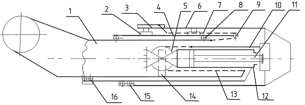
Scheme for extending telescopic sections
1 – first section; 2, 14 – slider; 3 – tensioner; 4 – second section; 5, 8, 9, 15, 16 – rollers; 6 – telescope base; 7 – shift chain; 10 – traction; 11 – rod; 12 – hydraulic cylinder; 13 – extension chain
Telescopic boom 4 consists of three sections placed one inside the other.
All sections of the telescopic boom move relative to each other on rollers and slides. The rod 11 of the hydraulic cylinder 12 is fixed to the end of the base of the telescope 6, and the hydraulic cylinder 12 moves freely, resting with the slider 14 on the surface of the first section 1. When extended, the hydraulic cylinder 12 moves to the left and pulls out the second section, rigidly connected to the hydraulic cylinder. At the same time, the first section is pulled out by chain 13. The first section 1 is pulled out through the roller 5 using a chain 13. One end of the chain is attached to the first section, and the second is secured to the end of the base of the telescope 6 by means of a rod 10.
When the sections are shifted, the hydraulic cylinder 2 moves to the right, retracts the second section 4. At the same time, through the roller 9 with a chain 7 connected to the first section, the entire system will be pulled into the base of the telescope 6. The tension of the chain 7 is carried out by the tensioner 3.
Non-rotating lifting-mast device of a submarine
The invention relates to the field of applied fluid mechanics and is intended for use on submarines (submarines) to reduce vibration, reduce flow noise and increase the reliability of mast-lifting devices (HMDs).
PMUs are installed on submarines and serve to provide communications, navigation surveillance, radar, celestial navigation and other measurements.
As a rule, the PMU is a round cylindrical mast with one or another attachment at the free end (radar antenna post, whip antenna, etc.) and installed in two or three round supports rigidly connected to the submarine hull. When raising and lowering the PMU moves along its longitudinal axis.
PMUs are divided into rotating, that is, those that rotate about their vertical axis during operation, and non-rotating, that is, those that do not rotate about their vertical axis.
When a submarine ascends to periscope depth or when moving in a periscope position, periodic hydrodynamic forces, caused by the separation of vortices from its surface, act on the raised PMU. These forces cause vibrations of the PMU, the amplitude of which at the free end in some cases exceeds the diameter of its pipe.
Vibration negatively affects the strength of the PMU, causes large errors in the operation of antenna posts and causes a decrease in the service life of the PMU. In addition, the noise caused by the flow around the PMU, the so-called flow noise, and the noise caused by the vibration of the PMU, as studies show, can reach unacceptable levels for newly designed submarines.
From all that has been said, it follows that measures aimed at reducing vibration of the pumping unit are of great importance.
The prototype of the proposed device is the “Non-rotating retractable submarine device” according to the author. St. No. 1839914.
The prototype is a PMU with a pipe and a fairing of large relative thickness attached to it in the rear part with a cut off aft part.
The disadvantages of the prototype include the following:
1. The large relative thickness of the fairing and the separation of the boundary layer that occurs near the aft section are the causes of significant noise emission during the flow.
2. Complex geometry of the fairing, which leads to more complex and expensive manufacturing technology for the PMU and its supporting structures.
The purpose of the present invention is to reduce the levels of vibration and noise emission of the PMU, reduce the breakers behind the mast, simplify the manufacturing and installation technology and reduce the likelihood of detecting a submarine when the PMU is operating using radar.
This goal is achieved using the combined design of the PMU. The mast of the device consists of two parts. Its upper part 1, streamlined by the flow, has a lenticular cross-section (see Fig. 1). Moreover, at the bow and stern ends of this profile there are protrusions 3 that fit into the guides of the PMU supports. The lower part of the mast 2 has a circular cross-section with a diameter equal to the chord of the profile of the upper part. So the supports remain round, as for conventional PMUs, only in the upper two supports there should be recesses - guides. The relative thickness of the profile of the upper part of the mast, as shown by design studies in relation to the developed PMUs, can change within the range of 0.35÷0.65.
For a PMU with a small load in the plane of the frame, a PMU version without protrusions included in the grooves of the upper supports is possible. Then the edges of the fairing are made radially rounded.
The proposed technical solution has the following advantages compared to the traditional design of the PMU. First of all, due to a decrease in the coefficient of drag force, the part of the PMU that goes into the flow, accordingly, the sound power of the vortex noise (flow noise) decreases by 2–4 times, calculated by the formula
Where: ; dн - pipe diameter or fairing width;
L—pipe or fairing extension; — flow speed;
C is the speed of sound in water; - density of water;
Sh is the Strouhal number.
At the same L, dн, , Sh, the noise power emitted by the PMU with a fairing will be 4-9 times less than that of the PMU with a round pipe. Considering that the width of the fairing, according to design studies, is 35–65% less than that of the pipe, we should expect a decrease in sound power by more than 10 times.
For a PMU with a fairing, the height and width of the breaker created by the PMU will be significantly reduced. These values, in accordance with the data of model and full-scale tests, will decrease in proportion to the decrease in Cx, i.e. 2÷3 times. Naturally, the probability of detecting a submarine in the PMF breakers will become lower.
Tests of dynamically similar models of PMU with fairings for one of the enterprise's themes showed that for PMU with the proposed cross-sectional shapes, the vibration amplitude will be 4–6 times less than that of a PMU with a round pipe. Consequently, for the PMU according to the proposed technical solution, the noise level resulting from the vibration of the PMU will be significantly reduced. The reduction in noise level can be assessed by the noise intensity, determined by the formula
where , is the circular frequency of oscillations,
c is the speed of sound in water, M is the bending moment, R is the distance to the point under study. As can be seen from the formula, the noise intensity will decrease in proportion to the decrease in torque, which in turn is proportional to the amplitude of the oscillations.
Significant differences between the proposed technical solution and the prototype are:
1. The mast consists of two parts of different sections.
2. The upper part, lentil or wing section, has or does not have (according to claim 2) protrusions in the bow and stern parts that fit into the recesses of the guide supports.
3. The lower part has a diameter equal to the chord of the profile of the upper part without taking into account the protrusions.
All this allows us to consider the proposed device to satisfy the “novelty” criterion.
Analysis of patent and scientific and technical literature did not allow us to find technical solutions with similar essential features. Therefore, we can conclude that the proposed solution meets the “significant differences” criterion.
The invention relates to shipbuilding, namely to lifting and mast devices for submarines. The lifting-mast device contains guide supports in the durable hull of the submarine and the wheelhouse fencing and a retractable mast made in the upper part of a lenticular shape in cross section, with protrusions on the bow and stern edges. At the same time, the retractable mast in the lower part is made round in cross section and fits into the strong hull of the submarine. The technical result is to reduce vibration and noise emissions. 1 ill.
Design features
Firefighting aerial lifts, like aerial ladders, have a fixed and rotating part. The non-rotating parts and rotation mechanisms of AL and APK are identical. Their main difference lies in the design of the cradle extension mechanisms.
The main mechanisms and units of car lifts are:
- base chassis;
- platform with supporting structures for the transport position of the boom;
- power group;
- hydraulic system;
- a support device including a frame, hydraulic outriggers;
- lifting and rotating part, consisting of a rotating tower, lifting booms and a cradle;
- built-in water and foam communications;
- mechanism for deploying booms, turning the turret and turning the cradle around a vertical axis;
- electrical equipment with locking and alarm system;
- controls.
Standard sizes
Firefighting car lifts, depending on the maximum working height of a fully unfolded car lift, should be manufactured in the following standard sizes:
| Standard size | Lifting height of the cradle, m |
| APK 10-15 | 10-15 |
| APK 16-21 | 16-21 |
| APK 22-28 | 22-28 |
| APK 29-36 | 29-36 |
| APK 37-48 | 37-48 |
| APK 49-56 | 49-56 |
| APK 56-64 | 56-64 |
At the customer's request, it is allowed to manufacture a firefighting aerial lift with a working height of more than 64 m with parameters according to the technical conditions for a firefighting aerial lift of a specific standard size.
Use of telescopic lifts in construction
Scaffolding, often used in various construction projects, takes a long time to erect, towers take up a lot of space, and stepladders are unreliable when working at heights. In contrast to this equipment, the telescopic lift is very compact, its price is not particularly high, it is quite mobile and convenient in everyday use.
A telescopic mobile lift is a device that performs the tasks of vertically lifting and lowering loads and people, and carrying out various works at height. Today they are quite widely used on construction sites for various works:
- during installation work;
- finishing works;
- electrical installation work;
- external and internal repair work;
- finishing works;
- various service works;
- when maintaining building facades;
Telescopic lifts are divided into areas of use:
- according to the maximum lifting height of the platform - usually 6 -12 m from the ground to the working platform.
- according to the size of the platform and load capacity - for 1 and 2 seaters and 150 and 300 kg.
What is the working height of the lift
The working height of a lift tower refers to the height that a person on a telescopic lift tower can reach. Usually it is equal to the maximum lifting height of the lift tower plus two meters. This characteristic is worth paying attention to, because often sellers of telescopic lifts indicate in the descriptions and basic technical characteristics exactly the maximum working height, while it is also necessary to indicate the height of the floor of the match telescopic lift tower.
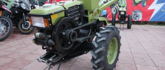
The mobile telescopic lift is raised to the height of the working platform using a special drive. Each working lift mast has its own electric drive, powered by one common hydraulic station.
One of the main features of modern mobile telescopic lifts is the special smoothness of lifting and stable fixation of the platform with a person at a certain height. This is achieved through the use of an electric drive in combination with a mechanical lowering-lifting system.
An important point is that the towers of such lifts have an emergency platform lowering valve. For example, if there is a power outage, a person who is currently on the ground can use a special emergency valve to lower the working platform solely using hydraulics.
The telescopic lift can be powered in several ways:
- from the power supply 220V;
- from 12V batteries;
- combined power supply - mains and batteries.
Modern mobile telescopic lifts comply with all requirements and standards for safe operation and have proven themselves to be excellent when working on construction sites in our conditions.
Laser levels, their types and application features
Do-it-yourself iron furnace cladding
The highest fire truck lift
On this topic ▼
Car lift Bronto Skylift F 112 HLA
Description and performance characteristics
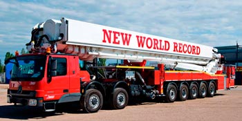
The Finnish company Bronto holds the height record for telescopic car lifts. Their telescopic car lift, Bronto Skylift F 112 HLA, is capable of lifting firefighters to a height of 112 meters. The record is that the platform can be at a height of 90 meters with the boom extending 25 meters outwards.
The mechanism is mounted on a standard Mercedes-Benz Actros 7660 chassis, modified into a seven-axle vehicle by Paul Nutzfahrzeuge. Five axles of the unusual chassis are steerable, and four are driven. In the transport position, the car lift has a height of 4 m and a length of 19 m, which allows movement on public roads. The curb weight of the “champion” reaches 77,000 kg.
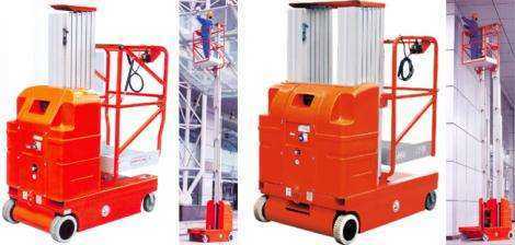
A mobile telescopic lift is an indispensable assistant in many matters.
Mobile telescopic lifts today are an indispensable device that is actively used both in construction and in other areas, for example, in manufacturing. This device is equally useful for performing a whole list of repair, finishing, installation and maintenance work that needs to be done at height.
Telescopic towers can be used with equal success both outside and indoors; they are actively used when working with large glass showcases, facades of modern huge shopping centers, warehouses and hangars, production and industrial facilities.
The main purpose of using this device is to quickly lift workers and loads accompanying their work to the required height. Thus, any installation or repair actions are carried out faster, easier and with greater convenience.
The start of the operation of the tower is carried out at the command of the managing operator, who is provided with two control units: one of them is installed in close proximity to the operator himself, the second is located on the lift chassis. The tower design uses not only a power supply system from a 220 V electrical network, but also from batteries. Also installed here are mechanical and hydraulic systems that perform the task of fixing the raised platform and make the process of raising and lowering the platform smooth. This provides additional convenience and safety.
This combined system of many mechanism options is very effective and safe. For example, if, while working at height, the power supply to the tower suddenly stops, then after opening the emergency valve, a hydraulic mechanism is activated that will smoothly lower the platform from the height. The emergency stop feature also provides operators and workers with many benefits and added safety.
Telescopic towers are easy to use. This became possible thanks to the following points:
- Low height of the equipment when folded, which makes transportation easier;
- The main material for making the tower is aluminum. It is lightweight and highly durable, making transportation, installation and operation of the device easier.
The manual telescopic lift itself can be transported even using an ordinary large elevator, since it fits easily there. An important feature of the device is that its platform drops very low and makes it easy to load tools and materials. The platform itself is very high quality and securely fenced, which will allow you to work without fear of an accidental fall. The machine operator climbs up the inside of the structure, which further increases his safety.
The “Temp” telescopic lift is also very popular due to its convenience and ease of use; you can read more about it on our website.
As for some of the disadvantages of telescopic mobile towers, there is only one - not too high load capacity, which imposes its own severe limitations. As a rule, this parameter for different device models is in the range of 100-300 kilograms. The maximum height that such a tower can raise is 20 meters. But do not forget that the height of the person working on the platform is also of considerable importance, since it can add up to 2 meters to the working height.
A mobile telescopic tower is an indispensable device when performing a large range of work. It is recommended to use it at an ambient temperature of -10 – +38Cº. These are some of the most popular types of special equipment on the construction market, which can be safely used in industry, construction, business and work in warehouses.
Designation and marking
The designation of a firefighting vehicle lift has the following structure:
AKP-32 (43118) mod. XHA-XX XX X,
Where:
- AKP / TPL – fireman's articulated car lift or fireman's telescopic car lift with a ladder, respectively;
- 32 – lifting height 32 meters;
- (43118) – index of the base chassis model according to the automotive industry classification (in this case, KamAZ-43118);
- Maud. ХХА – designation of the fire ladder model according to the developer’s system, indicating the modernization (A – first, B – second, etc.);
- XX – two-digit (three-digit) digital index to designate the model (01, 02, etc.);
- XX – conventional letter designation of the manufacturer;
- X – designation of a regulatory document (GOST, TU).
| Symbol of agro-industrial complex on fire extinguishing diagrams | Symbol of TPL on fire extinguishing diagrams |
Maintenance and inspection
On this topic ▼
Maintenance and repair of fire trucks
Types, procedure, timing
Ensuring the readiness and reliability of firefighting aerial lifts. For the effective use of automatic transmission or AL, maintenance and technical examination .
Maintenance includes all types of ongoing maintenance, as for fire ladders. The list of works is regulated by factory instructions.
Technical examination. Technical examination is carried out in order to ensure reliable operation of all automatic transmission mechanisms. The operation of all automation, blocking and alarm devices is checked along the entire border of the cradle's movement field, called the reach zone. Technical inspection is carried out by the owner. There are two types of technical examination:
- Partial – at least once a year.
- Complete – at least once every three years.
In addition, the load limiter is tested at least once every 6 months.
The working field (reach zone) is the area outlined by the top of the boom (the outer edge of the cradle) when maneuvering it with the maximum permissible reach and height for the corresponding lifting capacity. Thus, it includes the safe operating area of a fully loaded cradle, covering the lift height and boom reach. The zone is set by the manufacturer.
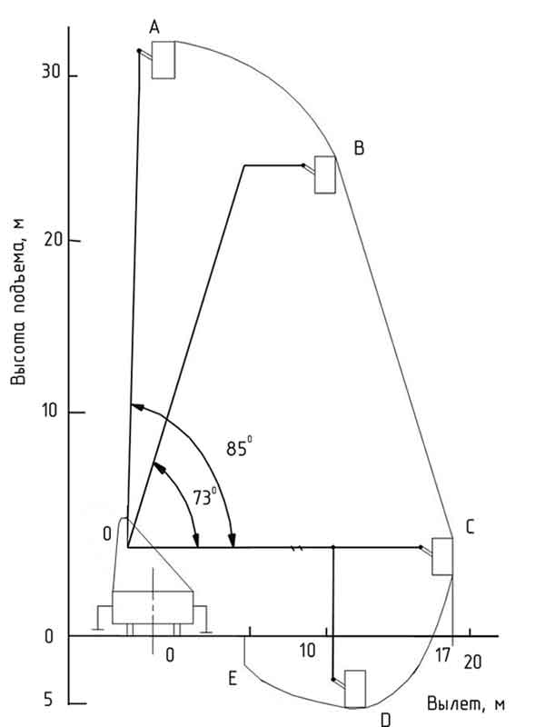
Working field of a firefighting vehicle lift using the example of AKP-32(4310)
During a partial technical examination, the following is carried out:
- external inspection (during an external inspection, the condition of the automatic transmission as a whole, its mechanisms, structural elements, and electrical wiring is checked;
- checking the operation of automation, blocking and alarm devices;
- dynamic tests.
A complete extraordinary technical examination is carried out in case of replacement of design elements and assembly units, as well as after a major overhaul of the automatic transmission.
Full technical examination includes:
- visual inspection;
- no-load test;
- checking the operation of automation, blocking and alarm devices;
- static and dynamic tests.