28.08.2017
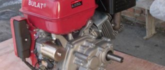
SMD motors are compact, economical, light weight, and easy to reconfigure (you can change the power of the device). All this ensured that these elements, intended mainly for agricultural machinery, became very popular in the CIS countries. The motors are equipped with high-pressure hydraulic pumps in order to maintain the hydraulic system. When installed on agricultural machines, they are supplemented with modern spark arresters. The devices are equipped with fuel filters that perform fine cleaning, which are washed from time to time without the need to disassemble the device, which facilitates maintenance.
The SMD-22 model is intended for grain harvesting machines “Niva”, SKD-6 M, “Yenisei”. Its modification with the prefix “a” is used on Yenisei combines.
Technical characteristics of the SMD-22/22a engine
Both motors have the following parameters:
- rated power - 145 hp. With.;
- operating power - 140 l. With.;
- rated speed - 2000 rpm;
- min. stable idle speed - no more than 650 rpm;
- Max. idle speed speed - no more than 2130 rpm;
- The nominal power mode differs in specific fuel consumption - 165 g/l. With. h;
- The operating power mode has a specific fuel consumption - 171 g/l. With. h;
- the main line of the lubrication system has an oil pressure of 2.8–4.5 kgf/cm2 (nominal speed) and at least 1.0 kgf/cm2 (min. stable idle speed);
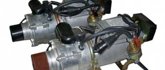
- the starting system is represented by a P-10UD starting engine, which has an RPD1.000 M gearbox;
- structural weight - 735–880 kg.
Engine cooling system SMD-60/62
The SMD-60/62 engine cooling system is closed. Water circulation is carried out by a centrifugal pump. The fan is six-blade, the radiator is six-row, tubular-plate, brass. System capacity - 48 l. The water pump and fan are driven from the crankshaft pulley via a belt drive. The belts are tensioned using a tension roller.
Coolant is pumped by a pump through channels in the front cover into the longitudinal water distribution channels of the right and left rows of crankcase cylinders. From the distribution channels it flows through the windows to the cylinder liners and cools them. From holes in the top plate of each cylinder bank, coolant is directed into the cylinder heads and discharged through a drain pipe into the radiator.
The SMD-60/62 diesel cooling system includes cooling of the starting motor and brake compressor. Coolant enters the starting engine through a pipe from the cavity of the sixth cylinder and is discharged from the head into the drain pipe of the left bank of cylinders. Coolant flows to the brake compressor from the distribution channel of the right bank of cylinders through a rubber hose and is discharged through a tube into the cavity of the water pump.
During operation of the starting engine, thermosiphon circulation of water occurs in its water jacket, but it is not so intense as to ensure long-term operation. Therefore, it is not recommended to idle for more than 3 minutes to avoid overheating of the starting motor.
To maintain the normal temperature regime of the SMD-60 diesel engine, a curtain is installed in front of the radiator, which regulates the air flow through the radiator depending on the load and time of year. On the engines of T-150 tractors produced since 1975, two thermostats are installed for faster warm-up after start-up and temperature control.
The radiator filler plug has a steam-air valve to regulate the pressure in the radiator. The steam valve releases steam into the atmosphere at a pressure in the system exceeding atmospheric pressure by more than 0.5 kgf/cm2, and the air valve releases air into the radiator at a vacuum of more than 0.01 kgf/cm2. The normal water temperature in the system is within 80-97° C. A short-term (no more than 5 minutes) increase in water temperature to 105° C is allowed.
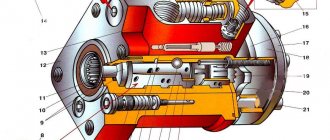
The design of the water pump roller seal is similar to that used on the SMD-14 diesel engine. The seal parts are interchangeable with these parts of the SMD-14 diesel engine (Fig. 57). In order to increase the wear resistance of the seal, the bushing 6, which works in contact with the graphite washer 7, is made of BR OS-5-25 bronze. To monitor the operation of the seal, a hole 20 is made in the pump housing. The appearance of water leakage from the hole indicates wear of the sealing parts. To remove the impeller 14 from the pump shaft in the event of replacing seal parts, three mounting holes 13 are provided for installing a puller.
On engines manufactured since January 1975, the fan is driven by two belts measuring 11-16X11X1450 instead of one belt measuring II-19X 12.5X 1450 mm. In this regard, the design of the pulleys on the crankshaft, water pump and tension roller has been changed.
The tension of the fan drive belts is changed by moving the tension roller along the groove of the bracket using a bolt that is screwed into the threaded hole of the roller axis. The tension roller bearings are permanently lubricated with grease and therefore do not require periodic lubrication.
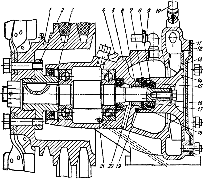
Rice. 57. Water pump for engine cooling system SMD-60/62 - diagram: 1 - pulley; 2 - hub; 3 - retaining ring; 4 — lubricant supply tube; 5 - pump housing; 6 — bushing; 7 — sealing washer; 8 - cuff; 9 — tube for draining water from the compressor; 10 — tube for removing air from the pump; 11 - cover; 12 — gasket; 13 - hole for puller; 14 — impeller; 15 - spring; 16 — pump roller; 17 — cuff ring; 18 — oil seal cage; 19 — retaining ring; 20 — control hole; 21 - channel for draining lubricant from the pump.
leave a comment
Structure of the SMD-22/22a engine
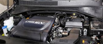
The engines are in-line 4-stroke, 4-cylinder, turbocharged and liquid cooled. The cylinders with a displacement of 6.3 liters have a diameter of 120 millimeters. The piston has a stroke of 140 mm.
The devices consist of:
- crankcase block;
- cylinder heads;
- crank mechanism;
- gas distribution mechanism;
- assembly units of fuel and air supply systems;
- cooling, lubrication and exhaust systems;
- starting device.
Repair of the cooling system of the T-150 (T-150K) tractor, Special equipment
The engine cooling system is closed with forced water circulation.
The main components of the cooling system are the water pump, fan and radiator.
Water is poured through the radiator neck until the entire diesel cooling system and the starting engine are filled. The water level should be 60-70 mm below the upper flange of the filler neck.
When the cooling system is filled, air is removed through a hose from the top of the water pump housing into the water pipe of the left cylinder head.
The water cooled in the radiator is pumped by a centrifugal pump into the water supply channels of the crankcase and through the windows in the channels enters the cavity between the walls of the block and the liners, washing the liners, cooling them.
Water heated during engine operation from the crankcase through the water-conducting holes in the crankcase and cylinder head rises into the water jacket of the cylinder heads, from where it enters the upper radiator tank through drainage channel 6 and pipe 9.
Passing through the tubes of the radiator core, the water is cooled by the air flow created by the fan.
When the starting motor is operating, local thermosiphon circulation of water occurs in the water jacket of the cylinder, and rapid heating of the starting motor is ensured.
The water temperature in the system can be adjusted using a curtain controlled by a chain from the tractor cabin. The temperature of the cooling water leaving the engine is controlled by a remote thermometer.
A plug with a steam-air valve is installed on the upper radiator tank. The steam valve serves to remove the resulting water vapor and opens when the excess pressure in the radiator increases to 0.5-0.7 kgf/cm2, and the air valve communicates the internal cavity of the radiator with the surrounding atmosphere when a vacuum of 0.01 kgf/cm2 occurs.
Drain water from the cooling system through two drain valves located on both sides of the crankcase and through the drain valve located on the pipe of the lower radiator tank.
Water pump. A centrifugal type water pump is attached to the front engine cover on a special platform.
The pump shaft rotates in a cast iron housing on two ball bearings. At the front end of the roller, a hub is mounted on a segment key, to which fan pulley 4 and a six-blade fan are attached with six bolts.
The water pump bearings are lubricated with diesel oil supplied from the engine oil line through a tube. Two rubber seals seal the oil cavity.
An impeller is installed at the rear end of the roller. The end of the roller entering the water cavity is sealed with a rubber cuff, which is pressed against the sealing washer by a thrust spring. A special brass clip is provided to center the spring.
The water pump roller is driven into rotation from the engine crankshaft pulley through the fan pulley using a belt drive.
The belt is tensioned by a tension roller, which rotates on two ball bearings with disposable lubrication, mounted on a fixed axis 6. A spacer ring is installed between the bearings. The front bearing is clamped by a cover, which is attached to the roller with two bolts.
Between the roller and the cover, on the one hand, and the shield, on the other, there are gaps for air circulation to ensure cooling of the bearings.
Water radiator. The engine cooling system uses a unified water radiator model 1UA. It is mounted at the front of the frame on stamp-welded brackets attached to the frame side members with three bolts on each side. Additionally, the radiator in the upper part is hingedly connected by a rod to a bracket fixed to the engine. The length of the rod is adjusted by a threaded fork, which is locked with a nut.
Vibration insulation of the radiator is provided by rubber gaskets installed above and below the shelves of the radiator brackets, as well as rubber washers installed on both sides of the rod mounting bracket to the engine. To prevent deformation of the rubber gaskets when tightening the radiator mounting bolts, a spacer sleeve is provided between the plates. The spacer is installed between the stamped thrust washers.
The radiator consists of the following main parts: core, upper and lower tanks and side struts. The core of the tubular-plate type radiator is made of vertical flat-oval brass cooling tubes and horizontal cooling brass plates soldered to them. The tubes are arranged in six rows of 43 in the four middle rows and 41 in the two outer rows. The total cooling surface of the radiator is 24.5 m2.
Upper and lower brass tanks are attached to the core support plates, which have a trough-shaped cross-section, between which two side stamped-welded steel posts are installed. Rubber sealing gaskets are installed between the flanges of the tanks and the support plates. The upper tank contains a filler neck, hermetically sealed with a type “B” car plug.
A pipe is welded into the filler neck, connected by a rubber hose to a water and steam removal tube, attached with two brackets to the left radiator support.
The plug is equipped with a steam-air valve. When there is excess pressure in the radiator, water vapor acts on the valve diaphragm, moves it upward, compressing the spring, and connects the internal cavity of the radiator through the steam outlet pipe to the atmosphere.
When there is a vacuum in the radiator, the air valve opens. In this case, the outside air, passing through the steam outlet pipe and the hole in the diaphragm, acts on the air valve, moves it down, communicating the internal cavity of the radiator with the atmosphere.
On tractors produced in 1971-1972. water radiators were equipped with tractor plugs, and the steam-air valve was placed in a separate housing, which was attached to the upper tank.
Two cast aluminum water supply pipes are installed on the lower radiator tank. A steel pipe using durite hoses connects the water supply pipes to the engine water pump.
A plug-type drain valve is located in the lower inlet pipe. The tap is opened and closed with the lower mesh of the radiator guard removed using a handle pivotally connected to the tap. The position of the handle, corresponding to an open or closed tap, is painted on the front frame beam. For ease of draining water from the radiator, a drain hose is attached to the tap.
A stamped fan casing (diffuser) is attached to the side posts of the radiator. To prevent air leaks from the engine compartment, rubber flaps are attached to the side pillars in front, and a lower apron is attached to the rear.
An oil cooler with a shutter is attached to the front radiator side struts. The curtain is designed to regulate the temperature of the engine and consists of a canvas sheet, a roller, a frame and guide rods. One edge of the canvas is fixedly connected by an axis to the oil radiator struts, and the other is secured to a rotating roller using hooks. The roller is a tube, inside of which there is a spring with tips, and the tip is rigidly connected to the tube using a pin.
The roller, using cylindrical protrusions of the tips, is connected to a stamped frame, which is hingedly connected to the guide rods. The guide rods are secured in the vertical posts of the oil radiator using cotter pins and are vibration-isolated by installing rubber bushings.
The curtain is controlled from the driver's seat using a cable and chain. When you move the chain towards you, the frame with the roller moves upward, the curtain fabric unwinds, and spring 6 is twisted. The curtain is wound onto the roller under the action of a spring when the chain is released. The curtain can be fixed in any intermediate position by installing a chain link in the slot of the guide sleeve located on the front panel of the cabin.
Home → Directory → Articles → Forum
There are still questions on the topic:
«Engine cooling system SMD-62
«
© 2007-2017 Stroy-Tekhnika.Ru - information system for construction equipment.
Materials: https://stroy-technics.ru/article/sistema-okhlazhdeniya-dvigatelya-smd-62