Do-it-yourself MTZ 82 PTO adjustment video
When assembling at the factory or after repair (for example, after replacing the brake bands), adjust the control mechanism in the following order:
1. Set the eccentric axis 15 (Fig. 56) to its original position so that the flat “B” is on the right vertically and secure with a locking plate 17 and bolt 16;
2. Disconnect rod 4 (Fig. 55);
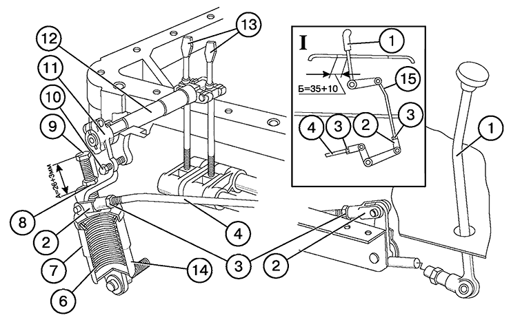
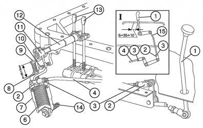
Rice. 55 Rear PTO control: 1 — control lever; 2 — adjusting fork; 3, 8 — locknuts; 4 - traction; 6 — springs; 7 — outer glass; 9 - thrust bolt; 10 — installation bolt (only for adjustment); 11 — control roller lever; 12 — control roller; 13 — adjusting screws; 14 — inner glass; 15 - thrust. Option “I” - for tractors with a unified cab.
3. Turn out bolt 9 to release spring 6;
To ensure safe disassembly of the unit, make sure that when turning out bolt 9, the upper cup 7 is in constant contact with it until the spring is completely decompressed.
4. Remove the rear axle hatch cover to gain access to screws 13;
5. Fix lever 11 in neutral by inserting an M10X60 bolt or rod 10 with a diameter of 8 mm into the hole on the lever and the corresponding hole on the rear axle housing;
6. Remove the locking plate 26 (Fig. 56), tighten the screws 21 until they stop with a force of 10 kgf using a wrench or pliers 100 mm long (torque 1 kgf*m), and then unscrew each screw 2-2.5 turns;
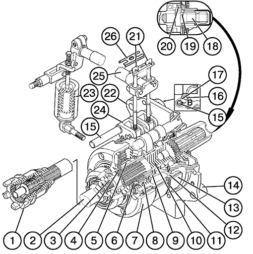
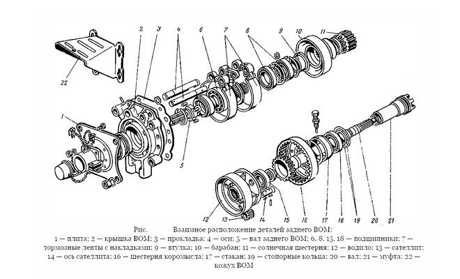
Rice. 56 Rear PTO planetary gearbox: 1 — drive shift clutch; 2 — ring gear shaft; 3 - nut; 4 - carrier; 5 — sun gear; 6 — satellite; 7 - ring gear; 8 — satellite axis; 9 — brake drum; 10 — PTO shaft; 11.13 — brake band; 12 — switching drum; 14 — rear cover; 15 — eccentric axis; 16 — bolt for fixing the locking plate; 17 — locking plate; 18 — removable shank; 19 — locking plate of the removable shank; 20 — shank fixing bolt; 21 — adjusting screws; 22, 24 — lever; 23 — spring mechanism; 25 — control roller; 26 — locking plate of adjusting screws.
7. Remove the bolt (rod) 10 (Fig. 55) holding the lever 11 in the initial position for adjustment;
8. Screw in bolt 9, directing its toe into the recess of the lid of the glass 7 to size “A” = 26. 29 mm;
9. Move lever 11 back to the “ON” position;
10. Install rod 4, by adjusting rods 4 and 15, set the swing zone of lever 1 in the middle part of the control panel slot. After completing the adjustment, reinstall the locking plate 26, the rear axle hatch cover, lock the rods 4 and 15 (Fig. 55), as well as bolt 9. In operation, if:
- The PTO slips;
- when switching, control lever 1 rests against the front or rear part of the control panel slot;
- the activation force on lever 1 is more than 12-15 kgf (120-150 Nm);
- unclear fixation of lever 1 in extreme positions or its unequal stroke when turning on and off,
adjust the band brakes using the external adjustment mechanism, for which:
- Install lever 11 (Fig. 55) in neutral, fix it in this position by inserting rod 10 with a diameter of 8 mm or an M10X60 bolt into the hole on lever 11 and the corresponding hole on the rear axle housing;
- Unscrew bolt 16 (Fig. 56), remove plate 17 from the splined shank on axis 15;
- Using a key S=13 mm, turn the eccentric axis 15 clockwise until the gap between the brake band and the PTO drum is selected (this can be determined by the inability to turn the PTO shaft by hand);
- Place plate 17 in place and tighten bolt 16;
- Remove the locking bolt or rod from lever 11 (Fig. 55).
After several external adjustments, the eccentric axis 15 (Fig. 56) may take the extreme left position (flat “B” will become vertical to the left), which indicates that the external adjustment reserve has been exhausted. In this case, turn the eccentric axle counterclockwise to its original position (the flat on the right is vertical), and then carry out the adjustment operations as described above (during assembly at the factory or after repairing the PTO). When the adjustment is carried out correctly, lever 1 (Fig. 55) in the “on” or “off” position should not reach less than 30 mm to the edge of the control panel slot and clearly pass through the neutral position.
On some batches of tractors, there may be no mechanism for external adjustment of the PTO control (items 15, 16, 17, Fig. 56). In this case, carry out the adjustment as indicated above for adjusting the PTO control after repair or during assembly at the factory. On tractors with a small cabin, size “B” is 50-60 mm. The effectiveness of the PTO brakes and the absence of slipping depends only on the spring mechanism, primarily on the presence of free zones for the operation of it and the levers associated with it. PTO slipping means that the spring mechanism or levers experience additional resistance when moving due to lack of lubrication in the hinges, increased contamination, abutment (touching) against adjacent tractor parts, etc.
TOP 7 best walk-behind tractors with power take-off shaft
The review of the best walk-behind tractors included seven models from reliable and trusted brands. These are middle-class gasoline and diesel walk-behind tractors with an optimal price-quality ratio, well-designed technical components and excellent ergonomics. The units are designed for most agricultural work in the garden, dacha or personal plot. Thanks to the power take-off shaft, various attachments can be attached to them:
- Plows and harrows;
- Hillers, cutters;
- Hitch for planting and digging potatoes;
- Mowers;
- Snow blowers;
- Carts for transporting various goods.
Standard delivery does not always include a full set of equipment. It must be purchased separately or in sets, depending on your needs. Reliable manufacturers always provide a wide selection of various components for their equipment.
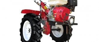
1. PATRIOT Ural with Extreme wheels (440 10 7581) 7.8 hp.
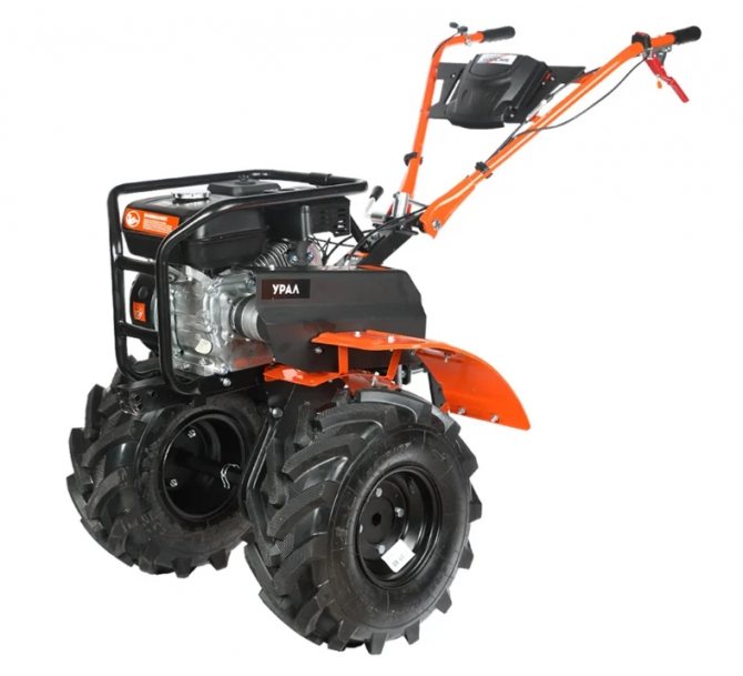
The powerful mid-class walk-behind tractor is distinguished by its high maneuverability on difficult soil, thanks to its large 50 cm Extreme wheels with deep tread. The domestically assembled unit is equipped with a durable P175FC gasoline engine with a power of 7.8 hp. sufficient for cultivating loose or rough soil, virgin soil. For convenience, the depth of the cutters can be adjusted. In terms of reliability, the walk-behind tractor can compete with more expensive analogues, which has gained popularity among experienced users. Among the technical shortcomings is weak welding of the opener fastening.
Advantages:
- high-quality assembly;
- cutters 90 cm wide;
- copes well with high loads;
- solid cast iron gearbox housing;
- on the steering wheel there is a box for keys;
- ease of maintenance;
- detailed and clear instructions.
Flaws:
- weak coulter attachment.
Daewoo Power Products DATM 80110 8 HP
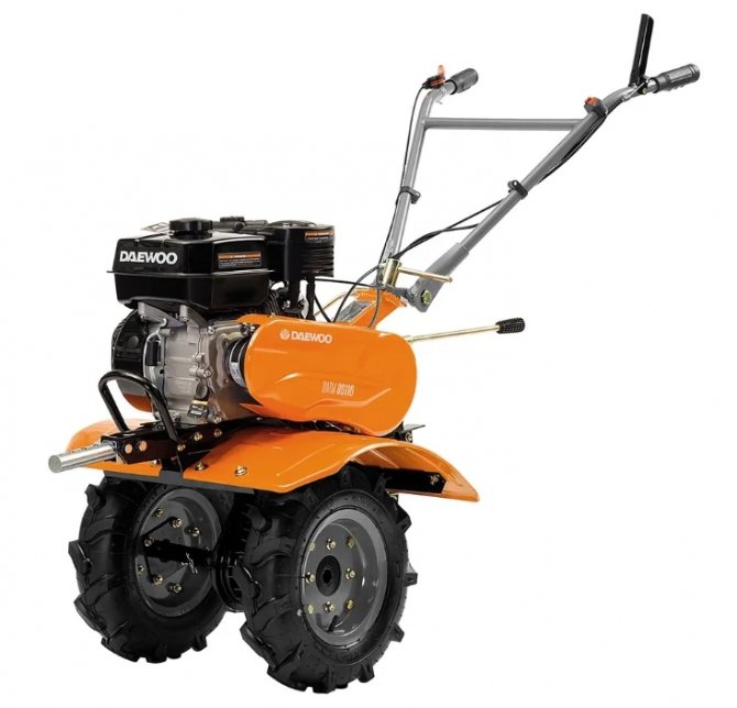
The strong and durable walk-behind tractor of the 225 series, according to reviews from owners, is very easy to use. The control panel is adjustable in two planes, professional handles do not tire the operator’s hands. Plus minimal vibrations and smooth running, which, coupled with good quality, made the walk-behind tractor in demand. Saber-shaped removable cutters are excellent for virgin soil and clay soil, and are adjustable in width. The successful model has no serious disadvantages; users noted only a short gearbox lever and expensive replacement belts.
Advantages:
- robust design and good assembly;
- hardened cutters are adjustable in width from 60 to 110 cm;
- cast iron gear reducer housing;
- reinforced opener;
- air filter with the “Cyclone” system;
- excellent maneuverability;
- perfect balancing;
- protection against corrosion and rust.
Flaws:
- expensive belts, but they are always on sale;
- short gear lever.
BISON MTB-400 7 hp.
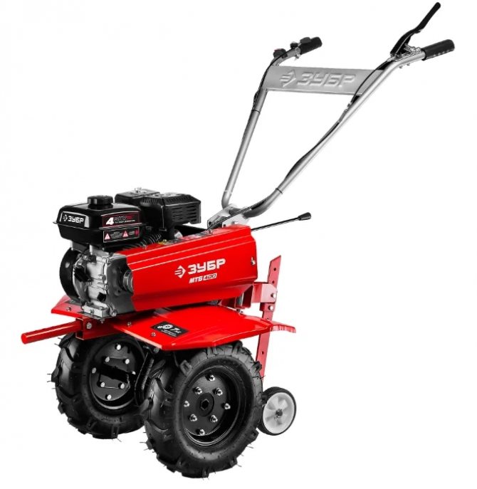
A high-quality walk-behind tractor from a domestic brand with reverse and low gear has become one of the cheapest in its segment. Despite the budget, the manufacturer equipped the model with a gear-chain reducer with an increased working life and a belt drive. Large pneumatic wheels provide excellent maneuverability. Moreover, the walk-behind tractor is easy to control, the coulter is combined with wheels and the walk-behind tractor can be moved without damaging the paving slabs or lawn. The set includes 6 cutters, furrow width 60-85 cm. The maximum depth of 35 cm, according to the owners, is somewhat overestimated by the manufacturer. However, the new product for 2020 is one of the best-selling models, which has received many positive reviews.
Advantages:
- low noise level;
- universal hitch;
- self-sharpening cutters;
- reliable gearbox;
- easy to start;
- 5 years warranty.
Flaws:
- picky about oil dosage;
- inflated technical characteristics.
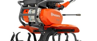
Huter MK-9500 9.5 hp
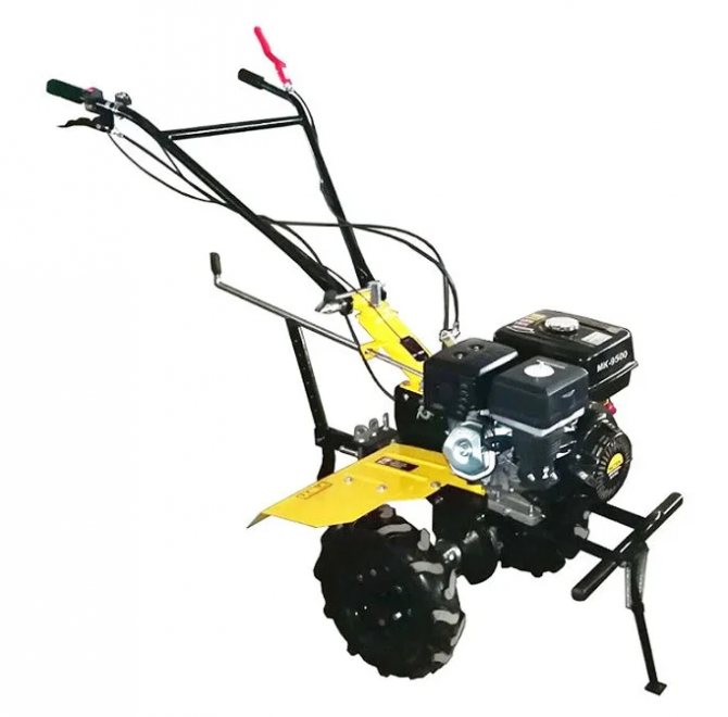
The most powerful model in the rating can rightfully be called a multifunctional agricultural machine. Thanks to its significant power supply, it is capable of any tasks related to cultivating the soil and caring for a personal plot. The high torque of the engine allows not only plowing, hilling, and snow removal, but also transporting bulk loads that are beyond the capabilities of light-class models. According to reviews, this is a very good walk-behind tractor with a wide range of capabilities, but its heavy weight and dimensions limit maneuverability.
Advantages:
- great functionality;
- high power;
- practical and reliable;
- 4-stroke internal combustion engine;
- excellent maneuverability;
- easy gear shifting;
- ease of maintenance.
Flaws:
- not suitable for small areas.
CHAMPION DC1163E 5.85 HP
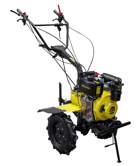
The popular model of a walk-behind tractor with a diesel engine has proven itself to be one of the most reliable and economical to operate. Maximum fuel consumption at average load does not exceed 290 g per kW/h, which is the best indicator in the class. The tractive effort of a diesel engine, even at low speeds, exceeds most gasoline counterparts. And to perform most jobs, according to the owners, half of its power is enough. The walk-behind tractor also features an electric starter and convenient controls. Users consider the only drawback to be the lack of a downshift range.
Advantages:
- efficiency;
- front support for stability;
- fast start;
- not demanding on fuel quality;
- high traction force.
Flaws:
- no downshifts.
Neva MB1B MA (RS950) 6.53 hp.
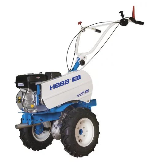
The Russian-made walk-behind tractor is assembled on a high-strength frame and is equipped with the most reliable units. The power plant uses a high-torque motor from the American manufacturer Briggs&Stratton RS950 series with reduced fuel consumption and a cast iron liner that prevents wear of the piston group. And the MultiAGRO multi-speed gearbox, developed by NEVA, is responsible for transmitting torque to the wheels. Its advantage lies in the optimal selection of movement speed for more efficient work performance. Thanks to these features, Neva MB1B, according to the owners, has become one of the best models of walk-behind tractors with a power take-off shaft in the middle class.
Advantages:
- low fuel consumption;
- three-speed gearbox with reduction row;
- high-resource internal combustion engine;
- excellent traction capabilities;
- high-quality cutters;
- cultivation width up to 125cm;
- Operation at sub-zero temperatures is allowed.
Flaws:
- high price.
Interskol MTB-1200/7 7 hp.
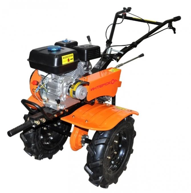
Since its introduction, the new product from the Russian company Interskol has won the trust of customers thanks to its excellent build quality and thoughtful design. The cultivator with a PTO is designed for year-round operation with various attachments available in the manufacturer’s range. Its seven horsepower is enough to cultivate all types of soil, including virgin soil, which is why this walk-behind tractor is recommended for purchase not only for private use, but also for work on farms. In addition to its main functions, the walk-behind tractor easily copes with transporting goods over long distances and is characterized by increased comfort.
Advantages:
- processing width per pass 1200 mm;
- high torque;
- comfortable steering with adjustments;
- long warranty (2 years);
- spacious fuel tank – 6 liters;
- Suitable for use on large areas.
Flaws:
- The included cutters are of poor quality.
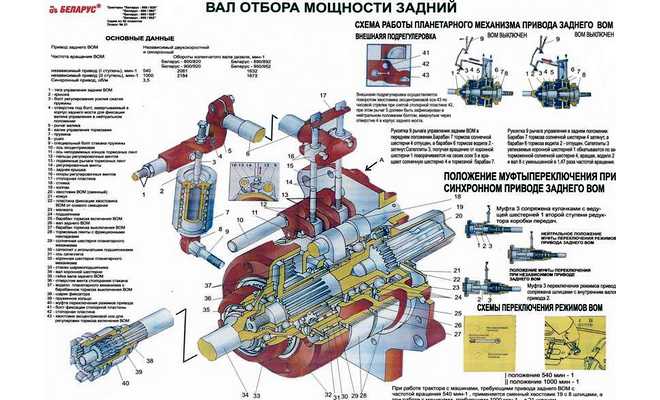
Diagram of the power take-off shaft of the Belarus MTZ-82 tractor
The diagram of this tractor device system includes:
- clutch support disk;
- drive type gear parts;
- side semi-independent take-off shaft and two-speed independent shaft;
- gear elements and driven shaft;
- gear clutch;
- intermediate and secondary shaft;
- gear drive parts and retaining bolt;
- carrier;
- stopping brake mechanism.
PTO MTZ-82 - diagram and drawing can be found in the user manual.
The main mechanism is a rear-type gearbox with 2 stages and a dependent and independent switching mechanism.
The rotation speed is carried out using a clutch, which is located on a spline on the machine. The device responsible for the mechanical control of the PTO is a hexagonal element located on the rear cover of the clutch housing.
Switching the cam mechanism sets the drive: the lever is moved forward, and the entire system begins to work; when the handle is moved to the “Off” position, the system stops working.
The lever can be in 3 positions: if you turn it clockwise, the dependent type will be installed; if you turn the handle counterclockwise, the device will switch to an independent type; the middle position is synchronous operation (the motor must be turned off before setting this position).
Independent and synchronous PTO drives "MTZ-82"
So, the design of the PTO of the MTZ-82 tractor is the same as that of the MTZ-80. The rear power take-off shaft of the MTZ-82 tractor is of a combined type. This means that the PTO can be equipped with both independent and dependent, that is, synchronous, drive. With an independent drive, the shaft rotation speed is determined by the rotation speed of the diesel engine, and with a dependent (synchronous) drive, it is determined by the speed of the tractor.
The independent PTO drive is connected directly to the engine flywheel. This ensures that the power take-off shaft rotates at a speed independent of the tractor speed. It will not affect the purity of rotation of the PTO and the engaged or disengaged clutch. The drive is independent - two-speed. It has two rotation speeds (540 or 1000 rpm), with a power unit speed of 2100 rpm.
The synchronous PTO drive is connected directly to the drive gear of the 2nd stage of the MTZ-82 gearbox gearbox. Therefore, the rotation speed of the power take-off shaft is tied to the speed of the tractor and is 3.5 revolutions for every meter of distance traveled by the tractor.
Switching to an independent or synchronous drive is carried out by a clutch moved using a leash located on the cabin floor. Namely: if the clutch driver is moved counterclockwise, then the synchronous drive is activated; if you turn it clockwise, the independent drive turns on. The middle position of the leash is “neutral”. In each of these positions, the shift clutch can be secured using a spring clamp.
The non-synchronous type should be started only when the engine is not running, or at the very minimum crankshaft speed. Synchronous - only on a tractor that is stopped.
We recommend reading: Chetra T9: technical specifications
The rotation speed of the power take-off shaft is standardized in certain values (540, 1000 rpm) specifically for correct operation with mounted and trailed equipment. Because otherwise, working on an additional device at an inappropriate speed can lead to either insufficient performance or damage to it.
When the independent drive is turned on, rotation from the internal drive shaft, which is located inside the secondary shaft of the gearbox, is transmitted through the shift clutch to the ring gear shaft of the PTO planetary gearbox.
When the synchronous drive is engaged, the clutch moves forward, disengaging from the internal shaft of the independent drive and connecting to the hub splines of the 2nd stage gearbox drive gear.
Adjusting the power take-off shaft
Adjusting the MTZ PTO (power take-off shaft):
- Place the vehicle on a special viewing platform.
- Set the axis of the central disk of the main system to its original position.
- The applied mark should be located on the right side in a vertical position, i.e. o will be on the right.
- Secure the risk using locking plates and screws.
- Disconnect the rod.
- Unscrew the cup screws to release the spring mechanism.
- Remove the rear drive axle hatch cover to gain access to the tension bolt head.
- Place the clutch handle in neutral mode and secure it with the M10*60 locking bolt. It screws into the hole on the lever, which should be located on the rear of the drive axle housing. After this, the locking plate is removed; it can be removed by removing the locking handle.
- Screw the thrust bolt into the outer glass until about (27-31 mm deep).
- Move the handle to the “On” position.
- Reinstall the traction mechanism. Then adjust the handle play by setting the required handle swing zone in the middle hole of the control panel slot.
- Check the speed rotation at the rear PTO shift speed.
After checking, the shaft is installed back on the MTZ-82 tractor.
Nuances of adjustment
Additionally, adjustment of the band brake mechanism may be required in cases where:
- the shaft begins to tow;
- the handle rests against the slot during switching;
- to activate the PTO, a force of more than 16 KGS is required;
- there is unstable fixation in extreme positions;
- The PTO engages unevenly (it either doesn’t work or works).
Procedure for adjusting the band brake mechanism:
- Set the handle to synchronous mode. Fix the position of the handle.
- Unscrew the nut and remove the plate from the shank slot.
- Using an open-end wrench, turn the axle mechanism clockwise until the gap between the gearbox and PTO is selected.
- Place the plate in its original position and tighten all the nuts into place.
- Remove the locking bolt from the handle.
- Perform adjustment.
- Turn the axle counterclockwise.
- Reassemble the mechanism in reverse order.
If, after performing work to adjust the brake mechanism, the axle has shifted to the left side of the vehicle body, this means that the power unit has used up its correction reserve.
In this case, you need to turn the eccentric counterclockwise, returning it to its original position. After this, the shaft is adjusted again.
Power take-off shaft on tractors MTZ-80 and MTZ-82
Power take-off shaft MTZ-80 (82)
- What is PTO?
- PTO adjustment
- Possible breakdowns
Adjusting the MTZ 80 PTO is a mandatory and regular procedure. The PTO circuit provides the attachment with the necessary force, which is transmitted directly from the power plant. Essentially, it is a combination device that requires regular maintenance. Otherwise, the tractor loses its functionality and is sent for repair.
In this article, we will look at which PTO is installed on the MTZ-80 tractor, the principle of its operation, adjustment, repair and possible problems. By the way, the MTZ-82 tractor is equipped with exactly the same device. Therefore, the PTO maintenance and repair scheme for these two machines is identical.
What is PTO?
The abbreviation PTO stands for power take-off shaft, which is installed on the MTZ-80 tractor or similar MTZ-82 to provide drive for mounted systems and units.
PTO shank
According to the installation method, the PTO can be of a side or rear type. The most optimal are rear-mounted power take-off shafts. They are installed on most wheeled vehicles and on the MTZ-80 tractor in particular. According to the principle of operation, the PTO of the MTZ-82 tractor can be of three types:
- Synchronous. In other words, such a shaft is called dependent. The speed of the unit directly depends on the mode of movement of the equipment. The drive to the power take-off shaft comes directly from the gearbox gearbox. The average rotation speed is 3.5 revolutions/1 meter of travel.
- Independent. Such a mechanism is connected directly to the MTZ-82 engine. Its rotation frequency depends on the engine flywheel with which the tractor is equipped. In addition, whether the clutch is on or off plays a role. For MTZ-80, the shaft rotation speed is 540 or 1000 rpm.
- Combined. Such a PTO can operate in the two modes listed above.
PTO adjustment
In order for the power take-off shaft installed on the tractor to function normally, it must be periodically inspected and adjusted. This applies not only to the MTZ-82, but to all tractors in general. The adjustment scheme looks like this:
- The eccentric axis is set to its original position. The applied mark should be on the right and located vertically. The position is fixed using locking plates.
- The rod is disconnected.
- The cup bolts are unscrewed to release the springs.
- The rear axle hatch cover is dismantled. This provides access to the head of the tension screw.
- The lever is moved to the neutral position and secured with a bolt. Then the locking plate is removed and the screw is tightened until it stops. After this, the bolt securing the lever can be removed.
- The thrust bolt is screwed into the outer cup.
- The lever is moved to the “on” position. Traction is installed.
- By adjusting the thrust, the required lever play is set.
- Upon completion of the adjustment, all parts are returned to their places, the rods and mounting bolts are reinforced with locknuts.
Possible breakdowns
The PTO installed on the MTZ-82 tractor may not work correctly for the following reasons:
A visual inspection revealed cracks in the lugs and the control roller. There are deep dents on the cup with springs
The MTZ-80 tractor definitely needs to be repaired; the troubleshooting diagram looks like this:
- align the holes of the shift roller and the rear axle. This can be done using the control lever. When the holes match, the installation bolt is screwed into them;
- the locknut of the adjusting bolt is loosened, which, in turn, is screwed into the lever of the switching roller until it stops;
- the locking bolt is screwed into the glass. Then the adjustment bolt is carefully removed;
- thus, the glass with springs is removed entirely. It is then disassembled and worn or damaged parts are replaced.
Claw Clutch Problems
In this case, the cabin of the MTZ-82 tractor is dismantled and the gearbox is disconnected from the rear axle. After this, the coupling is replaced. Repairing this part is not practical.
Extraneous noises produced by the rear axle
The power take-off shaft installed on the MTZ-80 tractor operates jerkily. Most likely, the spline joints have become unusable or the teeth of the central gear have ground off. The work flow diagram looks like this:
First you need to dismantle the PTO. The shaft is pressed out and the condition of the gear is assessed. To do this, the rear axle and dog clutch are disconnected. If large gaps are visually observed or the gear moves freely, the power take-off shaft must be sent for repair. After replacement, the shaft is reinstalled and adjustments are made.
The PTO shank moves freely
This means that the locking nut has become loose. As in the previous case, the unit is completely dismantled from the MTZ-82 tractor. If possible, the thread is restored and the nut is tightened until it stops. If not, you will have to disassemble the entire structure and carry out more labor-intensive repairs.
coupling
Upon visual inspection, oil smudges are visible on the shaft cover
This indicates wear of the cuff or gasket. In this case, the shaft is dismantled and the gasket between the PTO cover and the rear axle is replaced. If the leak comes from the shank side, the stopper ring is removed, the shaft is pressed out and the cuffs are replaced.
Possible faults
Possible breakdowns, repairs and malfunctions:
- Jamming of the shaft handle on machines: turning on requires a lot of effort from the driver. In this case, it is recommended to inspect the spring cup or cam-type coupling for damage and wear of parts.
- Increasing extraneous noise as torque increases. Such a malfunction may be associated with wear of the PTO splines and elements of the planetary gear mechanism. It is also worth inspecting the cuffs for elasticity and damage.
- The shaft is unstable and jerky. The breakdown may be related to the splined connections of the mechanism. Either the gear moves too freely along the base, because her teeth were worn out. It is necessary to disconnect the rear axle from the dog clutch. Inspect the width of the gaps. If the gap is too large, it is recommended to replace the shaft.
- The engine is not running at full power. The band brakes should be replaced and adjusted.
- The tail shaft moves too freely. In this case, it is recommended to tighten the loose nuts. Threads may need to be replaced.
Common malfunctions that occur during PTO operation
- A fairly common problem when operating the MTZ-82 PTO is jamming of the shaft control lever, or difficult, with significant effort, control of the clutch driver. This occurs due to a malfunction of the reinforcement mechanism (spring cup), or wear of the claw coupling.
- Extraneous noises that are increasing, along with an increase in the transmitted torque, as well as traces of grease on the back cover indicate significant wear of the shaft splines, parts of the planetary gearbox, and possibly loss of elasticity or destruction of the cuffs.
- If the power take-off shaft is unusually noisy and jerky, then most likely the splined joints have become unusable. Or the teeth of the central gear have worn out (ground down). In this case, the shaft is pressed out and the condition of the gear is assessed. You will need to disconnect the rear axle and dog clutch. If a visual inspection shows significant gaps, or the gear moves completely freely, then the PTO requires serious repairs. After replacement, the shaft is mounted in place, and it must be adjusted.
- When the MTZ-82 tractor does not produce the required maximum power when working with attached equipment, the reason for this lies in the band brakes. They require appropriate adjustment or complete replacement. In cases where adjustment does not help to get rid of such a problem, there is a need to remove the PTO from the tractor and control the thickness of the brake bands. When the thickness has decreased to 2.5 millimeters and below, these worn bands are replaced with new ones.
- The PTO shaft moves too freely. This sign means that the tension on the locking nut has become loose. The power take-off shaft needs to be removed from the MTZ-82 tractor. The fixing nut must be tightened until it stops. And, if possible, restore the thread, or “cut a new one.”
- A visual inspection reveals significant oil leaks on the power take-off shaft cover. This is a common sign of a worn cuff or gasket. In such cases, the PTO of the MTZ-82 tractor must be dismantled and the gasket between the PTO cover and between the rear axle must be replaced. If a leak occurs from the shank side, then you need to remove the stopper ring, press out the shaft and replace the cuffs.
We recommend reading: Bulldozer T-130: technical characteristics
In all cases when, in order to correct malfunctions, the power take-off shaft needs to be separated from the tractor, to do this, you first need to unscrew the rear cover fastening bolts, and then press out the PTO assembly with technological bolts. After this, you need to remove the brake bands and check their thickness. As already indicated, the brake band requires replacement with a new one if its actual thickness is less than two and a half millimeters. Typically, significant wear of the brake bands is indicated by the continued rotation of the shaft end when the PTO is turned off, as well as by its uneven rotation.
In any cases where the speed reducer gearbox has been dismantled or dismantled, it is necessary to check or adjust the PTO. To do this, a jack is installed under the drive wheels of the MTZ-82 tractor. After which the power take-off shaft rotates, alternating engagement of various gears. When performing such an operation, the power take-off shaft of the MTZ-82 tractor must be switched to synchronous mode. While turning, the gear wheels should rotate freely.
Material taken from the Tractor Review website (https://tractorreview.ru) - be sure to look at the information from the original source
Adjusting the rear PTO control mechanism
Maintenance of the rear PTO consists of timely adjustment of the control mechanism .
The need for adjustment may be due to:
- a) resting the PTO control lever against the lower edge of the cab, which may result in emergency PTO slipping.
- b) increased stroke of the PTO control lever.
- c) increased effort when moving the control lever from the “ON” position. to the "OFF" position.

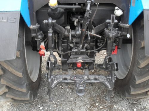
Rear PTO control
- 1 - control lever
- 2 - adjusting fork
- 3 - lock nut
- 4 - thrust
- 5 - spring cup
- 6, 7 — mounting bolt and nut
- 8 - spring
- 9 - glass lid
- 10 - lock nut
- 11 - thrust bolt
- 12 — installation bolt (only for adjustment)
- 13 — control roller lever
- 14 — control roller
- 15 — adjusting screws
Adjust the rear PTO control in the following sequence:
- Loosen the lock nut 10 (Fig. above) and tighten the thrust bolt 11 until it becomes possible to lock the cup cover 9 with the spring cup 5; screw in locking bolt 6 until it stops.
- Unscrew the thrust bolt 11 completely from the lever 13 together with the lock nut 10, then lower the spring assembly (consists of parts 5-9).
- Disconnect rod 4 from control lever 1.
- Align the hole on the lever 13 with the threaded hole on the rear axle housing and fix this position of the lever by tightening the installation bolt 12, size M10X60 mm.
- Provide free access to cover 15 (see figure here) of the rear axle and remove it.
- Screw in the adjusting screws 15 (Fig. above) until they stop; tighten them one by one, applying a torque of 8-10 N*m (0.8-1 kgf*m), then unscrew each screw 3 turns.
- Unscrew the installation bolt 12.
- Turn the spring assembly up and screw the thrust bolt 11 into the lever 13, directing its conical part into the recess at the end of the cover 9, until the mounting bolt 6 can be easily rotated.
- Unscrew bolt 6 enough to ensure free movement of spring cup 5 in relation to cup cover 9.
- Securely fix bolt 11 in lever 13, and bolt 6 in cup cover 9, tighten locknut 10.
- When folding or screwing the fork 2 onto the rod 4, lengthen or shorten the latter so that the adjustment margin “K”, that is, the distance from the rod fork to the lower edge of the cabin in the “ON” position of the control lever, is 45-50 mm.
- Finally connect rod 4 to lever 1 and replace the removed parts.
Warning: the spring assembly is compressed with a force of at least 200 kgf (2000 N). To avoid injury when removing or installing the spring, securely fix the cup cover relative to the spring cup by screwing bolt 6 into nut 7 until it stops in the spring or lock the cup with the lid using a special clamp.
Rear PTO
The rear shaft is a combined mechanism, that is, it can operate in two modes:
- Independent. In this mode, the number of shaft revolutions depends on the tractor engine speed. The drive, connected through a clutch to the diesel flywheel, provides two operating frequencies - 540 rpm and 1000 rpm at engine speeds above 2100 rpm.
- Dependent (or synchronous). In this mode, the shaft speed is determined by the speed of the tractor. In this case, the PTO receives rotation directly from the gearbox. The shaft rotates 3.5 turns per 1 meter of distance traveled by the tractor. Accordingly, the higher the speed, the faster the PTO will spin.
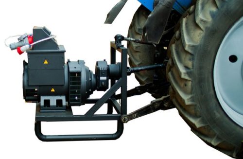
PTO MTZ-80, 82
The power take-off shaft (PTO) is designed to drive active working parts of machines aggregated with a tractor, as well as for stationary machines. Depending on the location on the tractor, the power take-off shaft can be rear or side.
The most common are rear power take-off shafts. On tractors MTZ-80, 82 the rear PTO is combined, as it can have an independent or dependent (synchronous) drive.
The independent drive is connected directly to the engine flywheel, which ensures PTO rotation speed regardless of the tractor speed and whether the main clutch is on or off.
The independent drive has two rotation speeds (540 and 1000 min) at an engine speed of 2100.
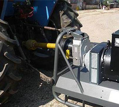
Side PTO
A side PTO is necessary to operate mechanisms and accessories that are mounted on the tractor in the front or side. Structurally, it is a separate mechanism in a cast iron body, attached with pins and bolts to the left hatch of the tractor gearbox.
The side PTO has only an independent drive and is connected to the gearbox.
To engage the side PTO, you need to pull up the rod, which is located in the cab to the left of the tractor driver’s seat. In this case, the rotary lever moves the roller with the driver, and the movable gear meshes with the gearbox gear. The side PTO operates in two modes: 535 rpm and 735 rpm. The mode is switched by a reduction gearbox.
PTO composition
The main components of the power take-off shaft include a 2-speed gearbox, a drive switch from independent to synchronous and a planetary gearbox.
The main mechanism that is responsible for turning on a certain type of drive and changing the torque is a planetary gearbox.
Planetary reductor
Its main part is the carrier. A sun gear is mounted on the carrier hub on a bronze bushing. Bushings are pressed into the carrier, on which three satellites are mounted. Using a spline connection, the carrier is engaged with the shaft. The shaft ends in a shank from which power is taken off. The carrier itself is covered by a ring gear with a drive shaft, to which rotation is transmitted through a clutch.
Prices for walk-behind tractors with power take-off shaft.
As already noted, such a device is not cheap at all, and various types of additional equipment for it are also not cheap. And therefore, in any case, it is worth considering the feasibility of such an acquisition. It is worth buying it if you really need all these functions. After all, you can simply plow a plot and take care of potatoes using a conventional walk-behind tractor or an inexpensive electric cultivator. But if other options are also in demand, and if you intend to use the unit constantly and not from time to time, then it will really be the best solution for you.
Depending on the set of functions, characteristics described above and the manufacturer, the final price is determined. Our online store Cheaptool is the official dealer for the sale of the best Italian gardening equipment BCS and French Caiman. We provide the most favorable conditions for our clients. If you have difficulty making a choice or need additional information about the product or prices, we invite you to visit our showroom in Moscow, where we will answer any question you may have and help you buy the best walk-behind tractor with a power take-off shaft for your dacha and demonstrate the performance of the product.
PTO malfunctions and adjustments
Given the simplicity of the design, the PTO mechanism of MTZ tractors does not require special maintenance procedures. The PTO control elements are the most susceptible to malfunctions. If any of the following symptoms appear:
- the on/off lever rests on the floor;
- the lever stroke is too large;
- turning on and off the PTO requires a lot of effort;
It is necessary to check for integrity and wear of parts, and, if necessary, make adjustments or repairs. Repair may also be necessary if the shaft begins to slip.
External adjustments
- The control lever is moved to the neutral position and fixed with an 8 mm thick rod.
- The slab and fence are removed from the shaft.
- The fastening bolt is unscrewed, the locking plate is removed from the shank, then the axle is turned clockwise until the gap between the drum and the belt is selected.
- The locking plate is installed back on the eccentric axle and secured with a bolt.
- After this, the lever can be unlocked.
If external adjustment has been made repeatedly, the axis may be turned all the way and it will not be possible to turn it further. In this case, you need to turn it counterclockwise to the extreme left position and start adjusting again.
A correctly carried out procedure can be seen if the control lever does not reach the end of the slot by about 3 cm and clearly passes (with a click) through the neutral position.
After repair work or replacement of any parts, internal adjustments must be made:
- The eccentric axis is set to its original position (far right) and fixed with a plate.
- The drive type control lever in the neutral position is locked with an 8 mm thick rod in the hole in the rear axle housing.
- The adjusting screws must be tightened with a force of 10 Nm and loosened by 2-2.5 turns.
- The power lever is set to the central position by adjusting the length of the rods.
- Use an adjusting bolt to achieve a distance of 32-35 mm on the control lever and tighten it with a lock nut.
- The fixing rod is removed.
If, when the PTO shaft is turned off, its shaft continues to rotate, or uneven rotation is observed during operation, it is necessary to adjust the brake bands. The adjustment is made as follows:
- The hatch cover is removed.
- The adjusting bolts are screwed in until they stop.
- The installation bolt is screwed into the lever and the bridge body.
- The servo-boost mechanism is completely removed.
- The rod is disconnected from the control lever.
- The adjusting bolts are loosened until the PTO shaft can be turned by hand.
- By twisting the fork the length of the pull is adjusted.
- The rod is attached to the lever.
- The servo-boost mechanism is installed in place.
PTO control "MTZ-82"
The planetary gearbox of the power take-off shaft on the MTZ-82 is controlled by 2 band brakes. The first brake drum is welded to the carrier, the 2nd drum is connected via a splined coupling to the sun gear.
To turn on the MTZ-82 power take-off shaft, the control lever in the cab should be moved to the rearmost position. The brake on the sun gear drum is applied while the brake on the carrier is released.
We recommend reading: YaMZ 534 engine: technical characteristics
From the ring gear, rotation is transmitted through the satellites to the carrier, and then from it directly to the shaft. The rotation speed decreases at this time according to the gear ratio of the planetary gearbox - by 1.47 times.
When you need to turn off the PTO gearbox, the control lever is moved to the extreme forward position. The brake on the sun gear drum is released, and the carrier brake is tightened. In this position, the carrier does not move, and the ring gear runs idle on the satellites. At the same time, the satellites rotate, also idle, the sun gear relative to the carrier hub.
The rotation speed of the power take-off shaft is switched by means of a clutch mounted on the shaft spline. The mechanism that does this is a hexagon located in the bottom cover of the one-piece clutch housing.
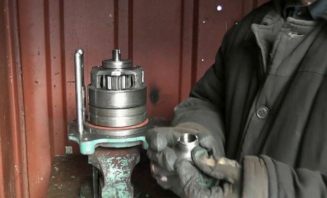
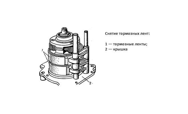
PTO dismantling
If the brake bands are heavily worn, and adjustment cannot achieve the desired effect, it may be necessary to dismantle the PTO to replace them.
- Remove the PTO visor and the shaft end cap.
- Remove the covers and unscrew the adjusting bolts of the brake bands.
- Using special technological bolts, the shaft is pressed out of the rear axle housing.
- If the thickness of the tapes is less than 2.5 mm, they must be replaced.
Situations when noise appears, which increases in proportion to the increase in torque, oil emissions on the housing may indicate that the shaft splines, elements of the planetary gearbox are worn out, perhaps the sealing lips have lost their elasticity or have collapsed. In such cases, it is also necessary to dismantle the PTO to assess the technical condition of its parts. If defects are found, damaged elements must be replaced.