81 82 83 84 85 86 87 88 89 .. CHECKING AND ADJUSTING THE FUEL INJECTION ADVANCE ANGLE OF YAMZ-236N, YaMZ-236NE2, YaMZ-236NE, YaMZ-236BE2, YaMZ-236BE, YaMZ-236B ENGINES
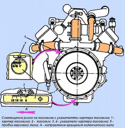
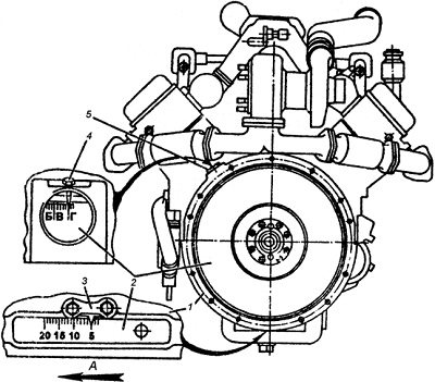
To adjust the fuel injection advance angle, two hatches are provided on the flywheel housing (see Fig. 63), and the angle values are marked on the flywheel in two places. For the lower indicator 3, these values are made on the flywheel in digital expression, and for the side indicator 4 - in alphabetic expression,
in this case, the letter “A” corresponds to the numerical value of 20°; letter “B” -15°; letter “B” -10°; letter "G" -5°.
Rotate the engine crankshaft clockwise (as viewed from the fan side) until the marks on the crankshaft pulley and the timing gear cover or on the flywheel with the indicator align, corresponding to the installation angle of the fuel injection advance:
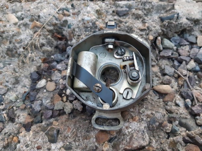
Rice. 63. Combination of marks on the flywheel with flywheel housing indicators: 1-flywheel housing; 2-flywheel; 3, 4 - flywheel housing indicators; 5-top hatch plug; A - direction of rotation of the crankshaft
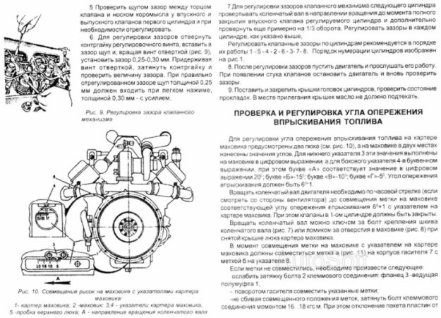
In this case, the valves in the 1st cylinder must be closed.
You can rotate the crankshaft with a wrench using the crankshaft pulley mounting bolt or a crowbar using the holes in the flywheel (Fig. 61) with the flywheel housing hatch cover removed.
When the marks are aligned, mark “A” on the end of the coupling (Fig. 64, 65) should align with mark “B” on the indicator. If the marks are not aligned, adjustments must be made.
The procedure for adjusting the injection advance angle of YaMZ-236NE2, BE2 engines (Fig. 64):
Loosen the tightening of bolt 2 of the terminal connection: flange 3 - drive coupling half 1;
By turning the damper coupling, align the indicated marks;
Without disrupting the aligned position of the marks, tighten the terminal connection bolt to a torque of 16.18 kgf-m. In this case, the deviation of the plate package from its position in one plane should be within ±1 mm. Take measurements near the places where the plates are attached. If corrugations appear on the plates 4, they are eliminated by alternately loosening and then tightening with a torque of 11.12.5 kgf-m the four bolts 5 securing the plates to the flange of the coupling half and to the damper coupling;
Check that the injection advance angle is set correctly.
Rice. 64. Drive coupling for the high-pressure fuel pump of YaMZ-236NE2, BE2 engines: 1-drive half-clutch; 2-bolt terminal connection; 3-flange of the coupling half; 4-plate drive; 5-bolts for fastening the drive plates; 6-washers; 7-damper clutch; 8-pointer; 9- high pressure fuel pump; A-mark on the damper coupling; B-mark on the index
Rice. 65. Drive coupling for the high-pressure fuel pump of YaMZ-236N, B, NE, BE engines: 1-drive shaft; 2-drive plates; 3-driving coupling half; 4-bolts; 5-bolt terminal connection; 6-bolts; 7-half-coupling driven; 8-fuel injection advance clutch; 9-high pressure fuel pump; A-mark on the coupling; B-mark on the index
The procedure for adjusting the injection advance angle of YaMZ-236N, B, NE, BE engines (Fig. 65):
Check the tightness of the coupling half 3 on the drive shaft 1 and the tightness of the terminal bolt 5 (tightening torque 43.2.58.9 N-m (4.4.6 kgf-m));
Unscrew (loosen) two bolts 4 and by turning the advance clutch, use the oval holes on the flange of the coupling half to align the marks “A” and “B”;
Without disrupting the aligned position of the marks, tighten the bolts 4 of the drive with a tightening torque of 43.2-58.9 Nm (4.4.6 kgf-m). In this case, the deviation of the plate package from its position in one plane should be within ±1 mm. Take measurements near the places where the plates are attached;
After turning the crankshaft, check that the injection timing is set correctly. The discrepancy between the marks should be no more than one division or 1° of rotation of the crankshaft.
Check the presence of oil in the fuel injection advance clutch (YAMZ-236N, B, NE, BE engines), and, if necessary, add oil. To check, install the coupling with the holes in the upper position and remove the plugs. When the clutch is slowly turned 70°, oil should begin to flow out of one hole. After adding oil, tighten the plugs.
The adjustment principle is absolutely independent of the brand of the power unit; it is common to all diesel engines.
Fuel supply advance angle and its installation. For the YaMZ 238 engine, the advance value is driven in near the mark located on the body of the injection advance clutch (from the end). This should be the number 20 or 18. As for the injection advance angle, it is usually determined by the first cylinder. It is checked using a manual booster pump, which is used to pump the power supply system of the power unit with fuel, making sure to first loosen the plugs on the injection pump housing to remove air. Once there are absolutely no air bubbles left in the fuel that comes out from under the plugs, they must be wrapped. Then you need to connect to the fitting of the corresponding fuel section. pump momentoscope, having previously removed the high pressure pipe of the 1st cylinder.
The injection timing is adjusted as follows. The power unit stop bracket is placed in the working position (the fuel supply by the plungers remains turned on) and the glass tube is filled with fuel by rotating the crankshaft. There should be no air bubbles entering the tube. Then it is necessary to remove the fuel from the glass flask so that its level is approximately in the center of the tube. This is achieved by shaking the flask. Next, the crankshaft is turned with maximum care. The rotation is made in the direction of rotation and is carried out using a key, while it is necessary to constantly monitor the position of the meniscus, which is located in the glass tube. The start of fuel supply to a certain section of the pump will correspond to the moment when the meniscus begins to rapidly rise upward. At this moment, the risk, which is located on the crankshaft pulley, should be opposite the risk with the numerical value indicated on the timing gear cover. During the entire angle setting procedure, an accuracy of ±1 must be maintained. The number on the mark must correspond to the one stamped on the housing injection advance coupling from the end. If the numbers do not correspond, then precise adjustment of the injection advance angle is carried out by shifting the fuel pump drive coupling relative to the flange. This is done with loosened mounting bolts. After the adjustment is completed, the bolts are tightened as tightly as possible, then the injection advance level is checked again. It is important to consider that the injection advance angle increases when the coupling half moves in the direction of its rotation. If you shift the drive coupling half by one division relative to its flange, then this will correspond to 4 divisions on the flywheel or on the timing gear cover. On injection advance couplings that were produced before 1963, the numerical value 0 was set. Now, instead of zero, the numerical value 18 is set (18° to the high altitude of the 1st cylinder). Marks with a value of 0 on the flywheel and gear cover until 1964 corresponded to an angle of 20° to east. m.t. 1st cylinder. The second mark is on the timing gear cover when counting from the zero mark in the direction. crankshaft rotation corresponded to an angle of 18°, and the fourth, in turn, corresponded to an angle of 16° to c. m.t. 1st cylinder. The second short mark on the flywheel, if counted from the 0 mark against the direction of rotation of the crankshaft, should correspond to an angle of 18°, and the fourth, respectively, 16° to e. m.t. 1st cylinder.
Based on personal experience, I can give the following tips and recommendations:
1) It is better to make a momentoscope yourself from several tubes. The first tube should be put on the fuel outlet twisted from the injector of the 1st cylinder, the last tube (having an internal diameter of about one and a half millimeters, transparent) should be located in a vertical position.
2) Leaks from the tubes are not allowed. It is necessary to carefully check that the tubes are put on tightly.
3) You need to pump up the diesel fuel to see it in the transparent tube. This is done by rotating one of the shafts. What kind of shaft it will be - choose for yourself.
4) After all of the above, you need to look at the marks on the flywheel. One of these marks indicates the beginning of fuel injection (ignition), the other - TDC of the 1st cylinder.
5) You should notice a slight rise in the diesel fuel in the tube while turning the shaft. This should happen before the 1st piston approaches TDC. This, in fact, is injection. Where the fuel rises, the shaft must be rotated extremely slowly.
6) The injection pump on the sliding mounts must be rotated so that the fuel injection itself corresponds to the injection mark marked on the flywheel. That's the whole task.
21 22 ..
Checking and adjusting the fuel injection advance angle of YaMZ-238PM and YaMZ-238FM engines
The fuel injection advance angle must be set using a momentoscope installed on the fitting of the 1st section of the fuel injection pump.
The injection advance angle should be:
For the YAME-238FM engine -23 °; for the YAME-238PM engine -22 °. The fuel injection advance angle must be set in the following order: make sure that the marks on the injection advance clutch and the drive half-clutch of the fuel pump drive are in the correct relative position. The marks should be on one side;
Remove the high pressure pipe of the first section of the injection pump;
Install a torque scope on the fitting of the first section of the pump (see Fig. 29);
Turn on the fuel supply using the regulator bracket;
Pump fuel into the engine power supply system by unscrewing the handle of the manual booster pump and, moving it up and down, pump the system for 2-3 minutes. After pumping, screw the pump handle all the way;
Rotate the engine crankshaft clockwise (as viewed from the fan side) using a wrench by the pulley mounting bolt or a crowbar by the holes in the flywheel until fuel appears in glass tube 1 (see Fig. 29). Pour excess fuel out of the glass tube by shaking it with your finger;
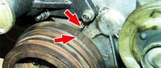
Rotate the crankshaft counterclockwise approximately 1/8 turn. Then, slowly turning it clockwise, carefully monitor the fuel level in the glass tube. The moment the fuel begins to move in the tube corresponds to the start of fuel supply by the 1st section of the pump. With proper adjustment, at the moment the fuel begins to move, the mark on the crankshaft pulley 2 should be opposite the corresponding mark on the timing gear cover (Fig. 30) or a similar mark on the flywheel 2 should coincide with the pointer on the flywheel housing (Fig. 31).
If at the moment the fuel begins to move in the pipe, the marks have not yet aligned, it is necessary to unscrew the bolts and turn the fuel pump drive shaft coupling on the flange against the direction of its operating rotation, then tighten the fastening bolts and check the injection timing again. The discrepancy between the marks should be no more than one division or 1° of crankshaft rotation.
If, at the moment the fuel begins to move, the risk tube has already passed the combined position, the drive roller coupling must be turned in the direction of its operating rotation. The displacement of the drive shaft coupling relative to its flange by one division corresponds to four divisions on the flywheel or timing gear cover.
After adjusting the advance angle, the coupling mounting bolts must be tightened.
If the engine is equipped with a high-pressure fuel pump drive of a new design with indicator 13 (Fig. 32), then the fuel injection advance angle is adjusted without a momentoscope as follows. Align the marks shown in Fig. 30 and 31; in this case, the mark “a” (Fig. 32) on the end of the coupling 12 should be aligned with the mark “b” on the indicator 13. If the marks “a” and “b” are not aligned, you need to unscrew the two nuts 7 and turn the injection advance clutch by oval holes on the flange
6 coupling halves align the indicated marks. Without disrupting the aligned position of marks “a” and “b”, tighten the nuts
7 bolts and flange of the coupling half and, by turning the crankshaft, check that the injection timing is set correctly.
Spare parts for Ural, Kraz, MAZ, Kamaz trucks. Engine parts YaMZ-236, YaMZ-238
Dismantling and installation of the YaMZ-236 fuel pump
___________________________________________________________________________
To adjust the fuel injection advance angle of the YaMZ-236 diesel engine of the MAZ-5551, MAZ-5335, 5336, 5337 and Ural-4320, 43206, Ural-5557 vehicles, two hatches are provided on the flywheel housing (see Fig. 40), and on the flywheel in Angle values are shown in two places.
For the lower indicator 3, these values are made on the flywheel in digital terms, and for the side indicator 4 - in alphabetic expression, while the letter “A” corresponds to the value in digital terms of 20°; letter “B” -15°; letter “B” -10°; letter "G" -5°.
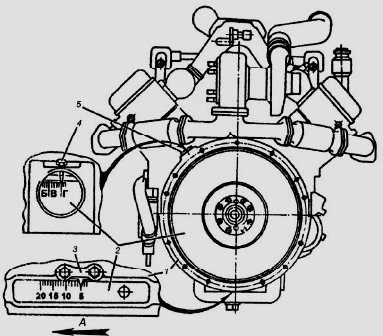
Fig.40. Combining the marks on the YaMZ-236 flywheel with the flywheel housing indicators
1 – flywheel housing; 2 – flywheel; 3, 4 – flywheel housing indicators; 5 – top hatch plug; A – direction of rotation of the crankshaft
Rotate the crankshaft of the YaMZ-236 engine of the Ural-4320, 43206, Ural-5557 and MAZ-5551, MAZ-5335, 5336, 5337 cars clockwise (as viewed from the fan side) until the marks on the crankshaft pulley and the timing gear cover align .
Or on the flywheel with a pointer corresponding to the installation advance angle of fuel injection YaMZ-236N, B: 15º+1º - on engines equipped with a V-shaped injection pump, the installation angle of advance of fuel injection is 10º...11º.
In this case, the valves in the 1st cylinder must be closed. You can rotate the crankshaft with a wrench using the crankshaft pulley mounting bolt or a crowbar using the holes in the flywheel with the flywheel housing hatch cover removed.
When the marks are aligned, mark “A” on the end of the coupling (Fig. 41) should align with mark “B” on the indicator. If the marks are not aligned, adjustments must be made.
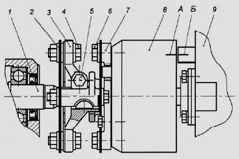
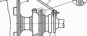
Fig.41. Fuel pump drive coupling for YaMZ-236 N, B, NE, BE engines
1 – drive shaft; 2 – drive plates; 3 – driving coupling half; 4 – bolts; 5 – terminal connection bolt; 6 – bolts; 7 – driven coupling half; 8 – fuel injection advance clutch; 9 – high pressure fuel pump; A – mark on the coupling; B – mark on the index
The procedure for adjusting the injection advance angle of YaMZ-236N, B, NE, BE engines:
Check the tightness of the coupling half 3 on the drive shaft 1 and the tightness of the terminal bolt 5 (tightening torque 43.2...58.9 Nm (4.4...6 kg/cm));
Unscrew (loosen) two bolts 4 and by turning the advance clutch, use the oval holes on the flange of the coupling half to align the marks “A” and “B”;
Without disrupting the aligned position of the marks, tighten the bolts 4 of the drive with a tightening torque of 43.2...58.9 Nm (4.4...6 kg/cm). In this case, the deviation of the plate package from its position in one plane should be within ±1 mm. Take measurements near the places where the plates are attached;
After turning the crankshaft, check that the injection timing is set correctly. The discrepancy between the marks should be no more than one division or 1º rotation of the crankshaft.
During TO-2, check the presence of oil in the fuel injection advance clutch of YaMZ-236 engines of MAZ-5551, MAZ-5335, 5336, 5337 and Ural-4320, 43206, Ural-5557 vehicles and, if necessary, add oil.
To check, install the coupling with the holes in the upper position and remove the plugs. When the clutch is slowly turned 70º, oil should begin to flow out of one hole. After adding oil, tighten the plugs.
Check and adjust the amount and uniformity of fuel supply in the following order:
Check the tightness of the discharge valves, for which:
Install a sealed plug on the bypass valve, supply fuel through the supply channel of the fuel pump at a pressure of 0.1...0.12 MPa (1.0...1.2 kgf/cm2);
When the rack position corresponds to the supply being turned off, fuel leakage from the fittings is not allowed for two minutes. If there is a leak, replace the discharge valve.
Check the opening pressure of the discharge valves of the YaMZ-236 fuel pump, which should be 0.85...1.15 MPa (8.5..11.5 kgf/cm2).
The pressure control of the start of opening of the injection valves is carried out at the moment the fuel begins to move from the fittings of the pump sections with a gradual increase in pressure at the inlet to the fuel pump and the position of the rack corresponding to the supply being turned off and the bypass valve hole being plugged.
If necessary, adjust the valve opening pressure by changing the number of shims. A 0.1 mm thick gasket changes the valve opening pressure by 0.1 MPa. Install a 0.4 mm thick gasket between the spring and the adjusting shims.
Check the fuel pressure in the line at the inlet to the fuel pump of the Ural-4320, 43206, Ural-5557 and MAZ-5551, MAZ-5335, 5336, 5337 vehicles.
The pressure should be 0.075-0.025 MPa (0.75-0.25 kgf/cm2) at a camshaft speed of 1030 min-1 for fuel injection pumps 604.5, 604.5-10 and 980 min-1 for fuel pumps injection pump 607.5, 607.5-10 when the control lever rests on the maximum speed limit bolt. If necessary, unscrew the bypass valve plug and use washers to adjust the opening pressure.
Check the power reserve of the YaMZ-236 injection pump rack. The power reserve of the rack is understood as the free movement of the rack (backlash) in the direction of turning off the feed at 450-500 min-1 and when the governor control lever rests on the bolt for limiting the minimum rotation speed.
If there is no power reserve of the rack, it is necessary to unscrew the power adjustment screw all the way and then use the rocker bolt to adjust the power reserve of the rack within 1-1.5 mm and lock it.
Check the start of turning off the starting fuel supply at 230–250 rpm when the control lever rests on the minimum speed limit bolt when the rack begins to move. If you need to increase the speed, remove the spring hook from the rack lever and screw it into the spring.
To reduce the speed, the hook is turned out. After this, place the hook on the rack lever.
Check the value of the average starting fuel supply, which should be at least 230 mm3/cycle at 80-10 min-1 of the pump camshaft. It is adjusted by the rocker screw only in the direction of increasing the fuel supply. After adjustment, caulk the rocker screw. Check the supply is turned off.
When the governor control lever rests on the maximum speed limitation bolt, check the rotation speed of the pump camshaft - corresponding to the beginning of the rack ejection, determined by the moment the rack begins to move in the direction of turning off the supply.
The start of rack ejection should occur at a rotation speed of (1065-1085) min-1 for the YaMZ-236N, YaMZ-236NE engines and (1025-1045) min-1 for the YaMZ-236B, YaMZ-236BE engines. Adjustment is made with the maximum speed limit bolt.
Check the rotation speed corresponding to the end of the rack ejection, determined by the moment the fuel supply to the injectors stops, when the governor control lever rests on the maximum speed limit bolt. The end of the feed cut-off should occur at a rotation speed of 50-100 rpm higher than the start frequency of the rack selection.
The injection pump of the YaMZ-236 diesel engine of the MAZ-5551, MAZ-5335, 5336, 5337 and Ural-4320, 43206, Ural-5557 vehicles is adjusted using a double-arm lever screw.
When the screw is screwed in, the rotational speed of the end of the ejection decreases; when turned out, it increases. At the same time, the start of shutdown also changes, so subsequent checking and adjustment is necessary.
Check the operation of the boost fuel supply corrector as follows:
Wash the mesh filter of the fitting in clean gasoline and blow it thoroughly with compressed air.
Clean the calibrated hole in the corrector body with soft wire with a diameter of (0.5–0.7) mm.
Check the tightness of the membrane cavity. To do this, supply air under a pressure of 0.06-0.01 MPa (0.6-0.1 kgf/cm2) to the hole on the cover 6 of the membrane housing. When the supply air duct is completely blocked, the pressure drop in the membrane cavity over a period of 2 minutes should not exceed 0.01 MPa (0.1 kgf/cm2).
Set the rotation speed of the YaMZ-236 cam shaft to 650-10 min-1, supply oil under pressure of 0.25–0.3 MPa (2.5-3 kgf/cm2) to the corrector, the control lever should be against the maximum limit bolt speed limit.
Adjustment of the cyclic fuel supply value of YaMZ-236 for Ural-4320, 43206, Ural-5557 and MAZ-5551, MAZ-5335, 5336, 5337 vehicles with an excess pressure on the membrane of 0 MPa is performed using the lever adjusting bolt. When screwing a bolt in, the feed increases, when turning it out, it decreases. After adjustment, lock the bolt with a nut.
The amount of cyclic fuel supply at intermediate air pressures on the membrane is adjusted by the spring housing. When the spring housing is screwed in, the fuel supply decreases; when turned out, it increases.
After adjustment, secure the spring housing with a nut. Before replacing a worn diaphragm (if necessary), you need to measure the amount of protrusion of the rod from the lower end of the nut at the diaphragm and rod assembly.
After this, replace the membrane and assemble it with the rod with the same amount of rod protrusion with an accuracy of 0.1 mm. When installing the boost corrector after dismantling (if necessary) on the regulator, use the stop lever to move the YaMZ-236 rack to the extreme off position and install the boost corrector into the regulator body, then release the stop lever.
Check the adjustment of the boost corrector and whether the fuel supply is turned off by the regulator.
Check that the cyclic feed is turned off with the stop lever. When turning 40-45 degrees from the original position, the fuel supply from the injectors of all sections of the fuel pump at any speed in any position of the regulator control lever should be completely turned off.
Dismantling and installation of high pressure fuel pump YaMZ-236
Dismantling the fuel injection pump section YaMZ-236
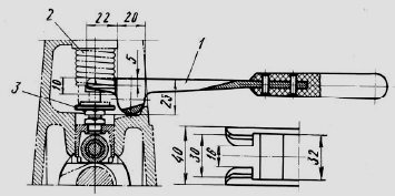
Fig.42. Lever for removing the injection pump pusher plate of the YaMZ-236 diesel engine
1 – lever; 2 – pusher spring; 3 – pusher plate
Disassemble the pump section of the YaMZ-236 injection pump in the following order:
Remove the side cover and rack cap.
Using a special lever (Fig. 42), compress the pusher spring and remove the lower pusher plate.
Remove the locking blocks, unscrew the fittings and remove the seats along with the discharge valves from the pump body with a special puller. To remove, screw the puller mandrel onto the threads of the discharge valve seat until the bushing stops against the pump body.
By turning the eccentric of the puller upward, remove the discharge valve seat.
Unscrew the locking screws of the plunger bushing and remove the plunger pairs from the pump body.
Squeeze slightly and remove the spring from the pump housing along with the upper plate, rotary sleeve and ring gear.
Remove the pusher from the guide in the housing.
Fig.43. Installing the Rotary Bushing with Ring Gear
Assemble the pump section of the YaMZ-236 injection pump for MAZ-5551, MAZ-5335, 5336, 5337 and Ural-4320, 43206, Ural-5557 vehicles in the reverse order.
When assembling, pay attention to the following:
The discharge valve with seat, as well as the plunger pair, are precision pairs, and each of them can only be replaced as a set;
Install the rotary sleeve with the ring gear assembly in the middle position of the rack (relative to the pump body) so that the slot of the rim is in the plane of the axis of the hole for the locking screw in the YaMZ-236 pump housing, and the middle tooth of the rim is in the middle cavity on the rack ( Fig. 43);
When installing the plunger pair, make sure that the rubber O-ring is put on the plunger sleeve; the flat at the bottom of the plunger shank should face the bushing retaining screw;
After tightening the locking screw of the plunger bushing, check the mobility of the rack and the amount of its stroke, which should be at least 25 mm; the rail should move easily, without noticeable difficulties;
Tighten the fitting to a torque of 100 - 120 Nm (10-12 kg/cm), after tightening each fitting, check the movement of the rack. After assembly, adjust the fuel pump with the regulator on a bench.
Installation of fuel injection pump on the YaMZ-236 engine
Install the driven coupling half onto the advance coupling (damper coupling) and secure with bolts.
Turn the injection advance clutch so that the bosses of the driven half-clutch are in a horizontal position and the mark on the end of the clutch is in the pointer area.
Install the coupling half flange assembled with the drive coupling half and plate packs on the drive shaft, while protrusion “a” on the coupling half flange should be on the left side when looking at the drive from the fan side.
Install the YaMZ-236 high-pressure fuel injection pump of Ural-4320, 43206, Ural-5557 and MAZ-5551, MAZ-5335, 5336, 5337 vehicles with an advance clutch (with damper) assembly onto the engine and secure it with bolts.
Before tightening the drive pinch bolt and after setting the injection advance angle, adjust the flatness of the plate packs by moving the coupling half flange along the drive shaft.
Install the fuel pump on the engine cylinder block in a vertical position, tighten the fastening bolts evenly, preventing the pump from clogging. The final tightening torque of the pump mounting bolts is 30-40 Nm (3-4 kg/cm).
Connect the sections of the YaMZ-236 diesel pump to the injectors with high-pressure fuel lines.
Adjust the injection advance angle.
Check the presence of oil in the housings of the high-pressure fuel pump and regulator, if necessary, add oil to the level of the hole for the oil drain pipe. Connect the oil inlet and outlet pipes and fuel lines.
After starting the engine, adjust the minimum idle speed of the crankshaft as follows:
Loosen the lock nut and unscrew the buffer spring housing by 2 - 3 mm.
Use the minimum rotation speed limit bolt (the control lever must rest against this bolt) to adjust the minimum idle speed until slight fluctuations in the crankshaft speed of the YaMZ-236 engine appear.
When the bolt is screwed in, the engine speed of the MAZ-5551, MAZ-5335, 5336, 5337 and Ural-4320, 43206, Ural-5557 cars increases, and when screwed out, it decreases.
Screw in the buffer spring housing until the instability of the rotation speed disappears.
It is strictly forbidden to screw in the buffer spring housing until its end aligns with the end of the locknut. After adjustment, secure the minimum speed bolt and the buffer spring housing with nuts.
The minimum idle speed can also be adjusted on a new engine during the initial period of its operation.
To adjust the fuel injection advance angle, two hatches are provided on the flywheel housing (see Fig. 1), and the angle values are marked in two places on the flywheel. For the lower indicator 3, these values are made on the flywheel in digital terms, and for the side indicator 4 - in alphabetic expression, while the letter “A” corresponds to the value in digital terms of 20°; letter “B” -15°; letter “B” -10°; letter "G" - 5°.
You can rotate the crankshaft with a wrench using the crankshaft pulley mounting bolt or a crowbar using the holes in the flywheel (Fig. 2) with the flywheel housing hatch cover removed.
At the moment of aligning the marks, mark “A” on the end of the coupling should align with the tip of the pointer (Fig. 3) or with the mark “B” on the pointer (Fig. 4). If the marks are not aligned, adjustments must be made.
Adjustment of UOVT in YaMZ 238
To set the spray advance angle, there are two control holes on the rotary wheel (flywheel) housing. And on the rotation wheel itself, angle reference points are marked at two points. The lower indicators are expressed in numbers, and the side indicators are expressed in letters.
To adjust the fuel spray advance angle, open the hole on the flywheel housing, rotate the engine crankshaft until the notches on the shaft pulley align with the timing gear housing or on the flywheel with a reference point. The resulting value should correspond to the setting angle of advance of the VT (6°–7°). These actions are performed, as a rule, with the valves in the 1st cylinder of the engine closed.
The crankshaft can be turned either with a wrench using the mounting bolt of the shaft wheel, or with a crowbar attached to the holes in the flywheel.

When aligning the marks, the indicators “A” on the end of the clamping device (coupling) must coincide with the arrow of the indicator or the letter “B” on the indicator. If the marks are not level, you need to continue adjusting.
Procedure for using a substitute
When working to set the advance angle, sparking must not be allowed in the engine compartment.
The ignition adjustment work depends on the engine brand. Setting the ignition timing without using a strobe is carried out according to the same principle as using it:
- You need to start the engine, first engaging neutral gear.
- Then, watching the displacement of the marks, slowly twist the distributor cap.
- When combining marks, the process should be stopped.
On a note. It must be remembered that the part illuminated by pulsed light appears static.
Sequence of adjusting the fuel injection advance angle
For high-quality adjustment:
- checking the tight fit of the coupling half on the drive shaft and tightening the terminal bolt;
- unscrew the two bolts and the rotary advance clamping device using oval holes, align the marks “A” and “B” on the damper coupling flange;
- tightening the bolts on the drive;
- performing measurements near the places where the plates are attached (the permissible separation of the plate package from the plane level is ±1 mm);
- turn the crankshaft and check that the UOVT is set correctly (the permissible discrepancy between the marks is equal to one division or 1° of crankshaft rotation);
- checking the oil level in the OVT clamping device;
- checking the correct installation of the UOVT.
To check this, you should place the clamping device with the holes in the upper position and unscrew the plugs. If you slowly rotate the clamping device 70°, lubricant should begin to flow from one hole. After adding oil, you need to tighten the plugs.
How to install the ignition on Yamz 236 video
CHECKING AND ADJUSTING THE ANGLE OF FUEL INJECTION ADVANCE OF ENGINES YaMZ-236N, YaMZ-236NE2, YaMZ-236NE, YaMZ-236BE2, YaMZ-236BE, YaMZ-236B
To adjust the fuel injection advance angle, two hatches are provided on the flywheel housing (see Fig. 63), and the angle values are marked on the flywheel in two places. For the lower indicator 3, these values are made on the flywheel in digital expression, and for the side indicator 4 - in alphabetic expression,
in this case, the letter “A” corresponds to the numerical value of 20°; letter “B” -15°; letter “B” -10°; letter "G" -5°.
Rotate the engine crankshaft clockwise (as viewed from the fan side) until the marks on the crankshaft pulley and the timing gear cover or on the flywheel with the indicator align, corresponding to the installation angle of the fuel injection advance:
Rice. 63. Combination of marks on the flywheel with flywheel housing indicators: 1-flywheel housing; 2-flywheel; 3, 4 - flywheel housing indicators; 5-top hatch plug; A - direction of rotation of the crankshaft
In this case, the valves in the 1st cylinder must be closed.
You can rotate the crankshaft with a wrench using the crankshaft pulley mounting bolt or a crowbar using the holes in the flywheel (Fig. 61) with the flywheel housing hatch cover removed.
When the marks are aligned, mark “A” on the end of the coupling (Fig. 64, 65) should align with mark “B” on the indicator. If the marks are not aligned, adjustments must be made.
The procedure for adjusting the injection advance angle of YaMZ-236NE2, BE2 engines (Fig. 64):
• loosen the tightening of bolt 2 of the terminal connection: flange 3 - drive coupling half 1;
• by turning the damper coupling, align the indicated marks;
• without disturbing the aligned position of the marks, tighten the terminal connection bolt to a torque of 16.18 kgf-m. In this case, the deviation of the plate package from its position in one plane should be within ±1 mm. Take measurements near the places where the plates are attached. If corrugations appear on the plates 4, they are eliminated by alternately loosening and then tightening with a torque of 11.12.5 kgf-m the four bolts 5 securing the plates to the flange of the coupling half and to the damper coupling;
How to set the advance angle on the YaMZ-238 engine
Setting the advance angle VT depends on the characteristics of each coupling individually, and the selection of the advance clamping device at the front end of the housing with numbers 18 and 20.
The UOVT should be set in the following sequence:
- Disconnect the high pressure pipe from the pipe of the 1st section of the injection pump.
- Fix the torque meter (momentoscope) on the pipe of the 1st section.
- Pump fuel with a hand pump into the engine power supply system, having previously unscrewed one of the plugs to bleed air from the injection pump housing.
- It is necessary to pump the system until the leaking fuel stops foaming, then tighten the plug tightly.
- You need to make sure that the fuel supply with the regulator bracket is turned on, and start turning the engine crankshaft to the right until fuel appears in the glass tube (chamber) of the torque meter.
- While continuing to slowly turn the crankshaft, you need to carefully watch the fuel in the glass chamber of the device.
How to set the ignition on a Lifan walk-behind tractor
Without performing a high-quality installation of how to set the ignition, it is necessary to perform a certain set of actions. On different brands of cars, the ignition settings have several differences.
Spark plugs and wires “fly” infrequently. Usually, the matter is in adjusting the ignition, and often problems occur due to the fault of the car owners themselves, who want to “improve” something during the operation of the engine. But, as we know, there is no need to refine something that works well. Especially if you don’t have the proper qualifications. It will only get worse.
Fundamentally! Before removing the distributor, if such a need arises, simply use chalk to mark the position in which it was. This will make the job much easier later.
- Remove the distributor cover.
- The ignition should be set to the first or fourth cylinder. For this purpose, a 13 mm wrench, a voltammeter, and a spark plug wrench will be useful. Although the method for setting the ignition is similar for each cylinder, you still do this following the example of the first one.
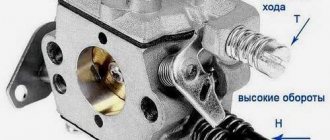
- There are 3 marker strips on the timing cover: medium, short and long. The small one is advanced by 10°, the medium one is 5°, the long one is not advanced.
- Remove the spark plug from the first cylinder. Our client is left with no need to unscrew the spark plugs. One is enough. The hole should be plugged with a rubber stopper (or at least with your finger).
- Using a special wrench, turn the crankshaft until the compression stroke begins in the first cylinder. An indicator that the compression stroke has begun will be the ejected plug.
- Turn until the mark located on the crankshaft pulley aligns with the mark on the cover. For 92 or 95 gasoline, it is recommended to use a regular label; if 72 or lower, then it is recommended to use a long one.
- Release the latches and remove the distributor cover.
- Rotate the crankshaft so that the external contact of the distributor rotor corresponds to the first cylinder (sequence: 1-3-4-2).
- Return the distributor, but do not tighten the nut completely.
- Now, of course, we will deal specifically with the question of what, how to adjust the ignition.
- Using a voltmeter, we check the circuit: connect one end to the “low-voltage” terminal provided by the ignition coil, the other to ground. This is necessary, first of all, to make sure that there are no problems in the wires and that the ignition coil itself is working.
- Turn on the ignition. Slowly turn the distributor so that the voltage goes to zero. If it is zero, then nothing needs to be done.
- Later, we turn the distributor until a voltage of 12 V appears, and in this position we already tighten the nut. This can also be done using a 12-volt light bulb. Here the direction of the current does not matter.
- Turn off the ignition. Place the distributor cover.
READ Lifan Diesel Engine for Motoblock
Ignition Lifan and DM 1
Now we need to check the correctness:
- Start the engine and start driving in a straight line up to 45 km/h.
- Switch to fourth gear and sharply increase the gas. After 2-3 seconds, a “beat” appears in the form of pops, hum, etc. It will disappear during acceleration.
- If the “beats” do not go away, it means that the ignition is very “early”; if they do not appear at all, it means that the ignition is “later”. The ignition should be adjusted again. If the earlier passage is turned one-half of a notch clockwise, if later, then counterclockwise.
- An important point: when our client needs to adjust, stock up on paint (or at least chalk) to mark the adjusted best position.
- Do not turn the pulley with the distributor removed! This will lead to complete confusion of all marks, and you will have to “regulate” from scratch.
In Russian cars, at the base of the distributor, 4.5 crescent moon icons of various sizes should be noted: one small, the other long. They need to cooperate.
To facilitate adjustment, foreign cars use special hazards that simply need to be combined. In many cases, figuring out how to set the ignition is much easier.
READ How to Cut Skirting Boards at 45 Degrees
The fundamental difference between diesel engines and gasoline units is that there is no forced ignition of the fuel. There are simply no spark plugs. The fuel is ignited by compression in the cylinder. For this purpose, accurate injection operation is required, so that by the time of compression, fuel and oxygen are already in the cylinder with a good percentage.
This ignition adjustment takes place similarly, unfortunately, to the preparatory removal of a set of decompression accounting programs.
Today, it will be useful to remove the oil filler neck and the engine meter.
The lever is set to the last position. Using a torque scope, we check the presence of a jet when cranking the crankshaft. The injection timing must correctly correspond to the injection mark on the flywheel.
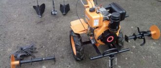
The cultivator is hitting the return line MTD T330t and why do you need a key 11
You should be aware that these are different units in their multifunctional capabilities. The difference between a walk-behind tractor and a walk-behind cultivator is that the latter is designed to work specifically with the ground (for example, plowing), while a walk-behind tractor is something universal. It works as a cultivator, but can also function as a pump, for example. A trimmer is a mower, then equipped with an internal combustion engine (usually electronic).
READ How to Install a Rotary Mower on a Walk-behind tractor
But their motor design is virtually monotonous. Accordingly, you can regulate the ignition of a walk-behind tractor, a walk-behind cultivator (a cultivator with an internal combustion engine) and a trimmer, of course, according to the same scheme. Their motor is designed identically. When, the motor of gasoline electric stations is also designed in a similar way.
To adjust the ignition on a walk-behind tractor, you simply need to adjust the gap. We insert paper folded 4 times between the flywheel and the mounting of the module, which is responsible for igniting the walk-behind tractor (usually, the module is not dismountable), press a little and tighten the module mounting bolts. When the flywheel is rotated, a steady, powerful spark should appear on the removed spark plug. What remains for our client to do? Sometimes it may be necessary to select a gap with sheet thickness options. It is important that there is no friction after removing the sheet.
Source
Fuel traffic assessment
- the fuel in the chamber begins to move;
- the marks on the rotary wheel casing coincide with the line whose value coincides with the number on the end of the OVT coupling;
- the mark on the crankshaft pulley is opposite the line with a similar number on the timing gear housing.
If at the time of the start of fuel movement in the chamber this coincidence of marks is not yet present, you need to:
- unscrew the mounting bolts;
- turn the motor shaft coupling half on the flange in the opposite direction of torsion;
- retighten the mounting bolts;
- check the position of the UOVT again.
When, during the start of fuel movement in the chamber, the marks have already passed the alignment point, you need to:
- Turn the motor shaft coupling half along the thread on the flange;
- the displacement of the coupling by one value unit relative to its flange is equal to 4 divisions on the flywheel or timing gear housing.
Stages of work
Setting the ignition timing with a strobe light is quite simple. Necessary:
- Carefully read the instructions for safe operation of the device.
- Turn off the engine.
- Connect the device to the battery using special clamps, strictly observing the polarity.
- Attach the signal cable to the spark plug wire of the first cylinder to form a connection with the device.
- During operation, it is necessary to prevent wires from getting into rotating units.
- Locate the white marks on the crankshaft pulley (or flywheel) and engine housing.
- Place the gearshift lever in neutral.
- Start the engine.
- Using dielectric gloves and waiting for the idle speed to stabilize, slightly loosen the bolt securing the distributor turns.
- Using a strobe lamp, highlight the previously found marks.
- Slowly rotate the distributor body until the marks coincide.
- Turn off the engine.
- Turn off the device.
- Having fixed the distributor body, you should test the vehicle.
How to check the accuracy of the fuel injection value
The discrepancy in readings should not exceed 1°. To check the accuracy of setting the feed advance angle on the YaMZ-238 you need to:
- Place the fixing element from the recess on the flywheel without securing it in the upper position.
- Rotate the crankshaft one and a half turns.
- Rotate the crankshaft moderately and observe the fuel in the glass chamber of the measuring device.
When the fuel begins to move in the chamber, the marks on the rotary wheel casing should coincide with the digital value indicated on the end part of the OVT coupling. Or the notch on the crankshaft impeller should be opposite the mark with a similar number on the camshaft housing.
If at the beginning of the movement of fuel in the chamber the marks have not yet coincided, you need to unscrew the fastening bolts, then rotate the motor shaft coupling half on the flange in the opposite direction of torsion, tighten the fastening bolts back, and again check the position of the fuel injection advance angle.
The steps above must be performed with special equipment. If there is not enough experience, knowledge and material and technical base to correctly set the engine ignition and regulate the fuel injection pump, it is better to turn to professionals with this issue. Incorrectly installed fire protection equipment is the cause of serious, expensive and, often, irreparable breakdowns.
Video on the topic: YaMZ-238 - drive, injection angles and fuel injection pump screw
source
Procedure for adjusting the ignition on turbocharged engines of the YaMZ 238 series
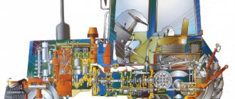
The 238 series Yaroslavl Motor Plant engine family is one of the most popular types of diesel power units.
The main difference between the engine systems of the series and the YaMZ 236 is the presence of additional two cylinders, which changed the technical performance of the engine for the better. However, the operation of even the most advanced mechanisms can raise a lot of questions among car owners. Especially when one of the most important mechanisms suddenly begins to act up. One of the frequently asked questions among truck drivers is how to set the ignition on the YaMZ 238. Before starting to study this issue, it is worth familiarizing yourself with the installation features of diesel units of the YaMZ 238 series. In total, the line contains quite a lot of modifications of advanced units of different systems, including YaMZ 238 M2 engine.
Adjustment
If you have identified a problem with out-of-phase phases, then you just need to find out how to set the ignition on a Ural motorcycle. This will make your life much easier in the future. Please note that the electronic ignition on the Ural motorcycle is regulated completely differently.
So, you need to adjust the ignition of the Ural motorcycle. To work, you will need wrenches, a screwdriver, and it is advisable to take a test light. Adjustments are made in the following order:
- First, set the engine to the top dead center position of the first cylinder, and this should be the compression stroke. You can check this as follows: unscrew the spark plug, plug the hole with paper and crank the engine. When the resulting plug is knocked out, you can stop, this is the desired position.
- Loosen the fastening of the breaker body, after which it is turned all the way clockwise, and a 12-volt test light is connected to the contacts;
- Turn on the ignition and turn the breaker housing until the light turns on. As soon as it lights up, you should stop and secure the lid. This completes the setting of the advance angle.
Izh Jupiter 5 ignition adjustment is done in approximately the same way. Now you know how to configure this system on your motorcycle.
After long and tedious attempts to start the motorcycle, it was decided to adjust the carburetor, but before you start adjusting the carburetors, you need to have the ignition adjusted. Because if the ignition is not configured correctly, it is very difficult to start the motorcycle, as in my case.
Design features of Yaroslavl diesel engines of the 238 series
The design of YaMZ-238 diesel engines assumes the presence of eight cylinders arranged in a V-shape. The volume of the combustion chambers is 1858 cm3 each. The diesel engine is a four-stroke type, with the cylinders operating in a 1-3-6-2-4-5-7-8 pattern. The power unit is equipped with a direct fuel injection system, and the compression ratio is 16.5.
The cylinder-piston group consists of a silumin piston complete with a cast iron liner. The CPG is attached to a cast iron connecting rod equipped with a bronze insert. The connection is made using a floating pin in combination with locking rings. The opposite end of the connecting rod is secured to the crankshaft journal with bolts. In this case, bronze sliding bearings are used.
The arrangement of cylinders in the units is two-row. There are four cylinders in each row. A separate cylinder head is attached to each row. Common to the two cylinder heads is a gear-driven camshaft. The crankshaft is equipped with counterweights and has 5 support points.
Gray cast iron is used as the material for casting the engine cylinder block. The casting of the main solid part that unites the cylinders of the unit is carried out in conjunction with the upper part of the housing. Modifications of cylinder blocks of YaMZ units produced before 2008 and currently are somewhat different: the “skirt” is somewhat shortened, and the engine itself has undergone certain modifications.
Differences between YaMZ turbocharged diesel engines
The need to increase the power of the diesel engine led to significant modifications to key components.
The characteristics of the crankshaft were changed, the structure of the cylinder block and CPG was modified. The power units of the YaMZ-238 family have acquired a system with pressurized air through a turbine. The main element of the system is a turbine installed in addition to the engine. To confidently comply with Euro-1 standards, turbocharged diesel engines of the 238 series received a liquid-oil heat exchanger, a high-performance water pump, and the CPG was supplemented with an effective cooling system. Plus, the diesel engine was equipped with a charge air cooling system and an improved fuel system.
Diesel units YaMZ-238 Turbo, corresponding to the Euro-0 standard, are essentially the same forced engines YaMZ 238 M2. One of the main design features compared to atmospheric modifications is the YaMZ 238 turbine in an improved version.
Further improvement of turbocharged diesel engines for heavy trucks made it possible to create structurally new components that comply with Euro-2 standards - this is how a series of Yaroslavl DE engines arose. The main feature of these models was a modified high-pressure fuel pump.
Despite solid work on improving the "heart" of the truck, some parameters require adjustment in accordance with the characteristics of the vehicle and its features. One of the most important tasks for the correct and safe operation of a heavy truck is the correct setting of the injection (ignition) timing on diesel engines.
The presence of a turbine - a unit capable of increasing engine power by more than 50% - requires a special approach to the selection and installation of individual mechanisms. Thus, the turbine on the MAZ YaMZ 238 is most often used of the TKR 9-12 type, as well as similar modifications. Such injection systems are capable of working with most engines of the YaMZ 238 series without any particular difficulties. Productivity in this case reaches a level of 0.25-0.35 kg/s at a rotor speed of up to 50 thousand revolutions per minute. There are also similar models of Czech-made turbines.
Procedure for setting the injection advance angle
The designers of turbocharged systems have taken care of the convenience of setting ignition parameters on heavy-duty engines - two holes can be found on the flywheel housing. The part itself bears marks that help set the angles. It looks like marks on the flywheel, equipped with numbers from 5 to 20 with an interval of 5° (on the lower indicator) and marks with letters from A to G (on the upper crankcase indicator).
To adjust the injection advance angle, open a hole in the housing and rotate the crankshaft until the notches on the pulley and timing gear housing are aligned. In this case, the obtained value should correspond to 6-7° - the setting parameter for the injection moment. When the shaft is rotated, the valves in the first cylinder must be closed.
To ensure correct adjustment and uninterrupted operation of the unit, you must carefully perform the following sequence of actions:
- check how tightly the coupling half is seated on the drive shaft and tighten the terminal bolt;
- unscrew a pair of bolts and rotate the clamping device through special holes until marks A and B on the damper coupling are aligned;
- tighten the fasteners on the drive;
- take measurements in the areas where the plates are attached (permissible deviation +/- 1 mm);
- turn the crankshaft and check that the fuel injection advance angle is set correctly (the error is one division or 1 degree of shaft rotation);
- measure the oil level in the clamping device;
- carry out actions to check the parameters of the injection advance angle.
You can check how well the YaMZ 238 turbo engine can perform its functions after adjusting the ignition and check the sufficiency of oil by installing the coupling with the holes facing up and removing the plugs. When turning the clutch until an angle of 70 degrees is reached, oil should come out of one of the holes. If necessary, add oil and then return the plugs to their place.
Setting the advance angle
The required advance value is located next to the special mark. The YaMZ 236 fuel injection advance clutch is where this risk is applied. The normal value is 20 or 18 points. The angle of the fuel mass itself is determined by the primary cylinder.
Control is carried out using a conventional pump. So, they work on the power supply system of a car engine, without fail, first opening the valves through which air escapes from the engine. After the air masses have come out without any residue, the plugs are wrapped. Next, you should connect the momentoscope device to the fittings of the special section from the fuel pump. Before carrying out the procedure, it is necessary to remove the injection pump of the Yamz 236 cylinder.
Read also: Connection diagram for generator 2108 to 2106
The advance is adjusted as follows:
- the bracket from the working power apparatus is transferred to the working state;
- drain all the fuel from the glass container until the volume of liquid reaches the mark in the middle part of the tube;
- carefully turn the crankshaft.
All movements must be made strictly in the direction of torsion. The current position of the meniscus in the tube must be constantly observed and monitored. Its sharp rise signals the start of fuel start-up by a certain section. The line marked on the pulley should be opposite the line with the number marks. The procedure for setting the angle requires special accuracy up to 1 value.
Method of adjusting the ignition using a strobe
Before you begin the tuning procedure, you must warm up the engine until it reaches optimal operating temperature. Then connect the device to the truck’s network and follow these steps:
- Unscrew the nut on the distributor cap;
- remove or plug the vacuum regulator hose from the distributor (if any);
- Reduce engine speed to a minimum and illuminate the marks using the device. If the ignition installation is done correctly, the moving mark should coincide with the fixed mark;
- make adjustments if the marks do not match: turn off the unit, loosen the distributor fasteners, turn its housing to the required amount;
- perform a re-check using the device;
- If successful, secure the fixing nut to the body.
Ignition adjustment on diesel units
In other cases, it may be necessary to adjust the ignition timing. To do this, just unscrew the locking screw a little and set the position of the distributor so that the mark coincides with the mark. The locking screws should then be tightened. They must be tightened using a torque wrench to control the tightening force. The tightening value should be 25 N/m.
After this, you need to connect the temperature sensor and sharply press the gas pedal three times. Then look again at the coincidence of the marks. If the circumstances are positive, the measuring instruments should be removed. Do not forget about the previously disabled fan drive.
How to check the correct injection angle
In addition to the described methods for adjusting the injection timing, it is possible to experimentally select the parameters of the injection timing on vehicles where a YaMZ 238 turbine is installed. To do this, it is necessary:
- Having installed the pulley, try to start the engine. If the attempt is unsuccessful, turn the fuel pump pulley in relation to the belt by 2-4 teeth. Try to start the engine again;
- After starting the diesel engine, you need to evaluate the quality of its operation. Extraneous noises and knocks during engine operation indicate the need to turn the pulley 1-2 teeth in the direction opposite to rotation. If the result of starting the unit is an abundance of smoke, it means that there is a late injection advance angle. Then the pulley needs to be turned 1 tooth in the direction of rotation.
There is another way:
- Remove the tube supplying fuel under pressure to the first cylinder of the unit, put a transparent flexible hose on it and install it vertically.
- Turn on the ignition and rotate the pump pulley. This must be done extremely carefully.
- Assess the fuel level in the tube and fix the limit at the top point.
- Having noted the moment of the highest fuel level, leave a mark on the pulley.
- Carry out the steps to install the crankshaft and camshaft.
Upon completion of the procedure, start the diesel engine and monitor its operation. If signs of a late or early injection angle are observed, repeat the adjustment steps.
Expert advice
It is best to make a torque scope yourself so that the device fits perfectly to the engine. You can create a device from several tubes. During operation, it is necessary to monitor the tightness of the tubes and prevent leaks.
Another important point is the process of pumping diesel fuel until the tube appears in sight. Inflating is done by rotating the shaft. A rise in the fuel mass will be noticeable when the shaft is rotated before directly approaching the elements of the first piston. It is important to rotate the shaft smoothly and very slowly.
With slippery fastenings of the YaMZ 236 m2 fuel injection pump, it is important to rotate it so that the injection of the fuel mass corresponds to the injection designation on the flywheel.
Turn the engine so that the flywheel pulley scale shows 20 degrees. At the same time, so that the mark on the fuel pump coupling is at the top; if the mark on the fuel pump pulley is not visible from above, then turn the engine another 360 degrees, again setting 20 degrees according to the mark on the crankshaft pulley.
Unscrew the two fastening bolts on the fuel pump coupling and turn the coupling to the maximum late ignition. This means that if you look at the pump from the radiator side, then counterclockwise.
Read also: Fuel-air mixture ratio
Then unscrew the high-pressure fuel supply pipe to the first cylinder from the fuel pump. And the recess on the plunger, the place where the tube stood, should be drained of fuel by blowing or using a cloth.
Next, rotate the clutch clockwise in the direction of early ignition, very slowly, you can tap it with a mounting tool, since it is difficult to do this with your hands slowly and without jerking. Scroll until fuel appears slightly, slightly in the recess of the plunger, in the cone of the place where the high-pressure tube is screwed onto the first cylinder, on the pump. Fill this cone a third to a quarter full.
Owners of heavy-duty vehicles with diesel engines produced at the Yaroslavl engine plant are faced with problems adjusting the ignition of the high-pressure fuel pump (HPF). However, how to set the ignition of the YaMZ 238, adjust and check the fuel injection advance angle (FIA) can be found in this article.