Has your D-160 (D-180) engine worked so many hours that there is no point in repairing it? So it’s time to replace the tractor’s “heart”!
How to quickly and inexpensively replace the engine of a T-170, T-130, B-10 tractor?
The answer to this question is known to regular customers of PromTorg LLC!
Our company supplies D-160, D-180 engines for T-170, T-130, B-10 tractors, produced by ChTZ. Prices for these products are available to everyone. Depending on the volume of supplies, we also provide discounts to regular customers.
Engine D-160 for bulldozers T-130, T-170, B-10M after major overhaul
New supply of D-160, D-180 engines for bulldozers manufactured by ChTZ-Uraltrak after major overhaul.
What is more profitable - an overhauled engine or a new one?
Given the current economic situation in the country and the sharp increase in the dollar exchange rate, the price of new engines has almost doubled! Therefore, purchasing an overhauled engine is becoming increasingly important. Decide for yourself - engines that have been overhauled have a lifespan of up to 90% of a new engine at half the cost!
What does a major renovation include?
1. Replacement of the piston group (liner, piston, rings)
2. Replacement of main and connecting rod bearings
3. Grinding/polishing of the crankshaft (no more than P1)
4. Repair of the cylinder head, adjustment of valve clearances, processing of the cylinder head plane
5. Adjustment (repair if necessary) of fuel injection pump and injectors
6. Replacement of all rubber goods and gaskets
7. Repair (replacement if necessary) of starter, generator, pneumatic compressor, turbocharger
8. Replacing the clutch (if the engine is supplied with the 1st complete set)
9. Running in the engine on a stand under load
10. Painting
Completeness
We can offer you engines of two complete sets:
№1 complete engine with electrical equipment (starter, generator), pneumatic compressor, clutch. In this complete set, the engine is usually purchased for converting a vehicle from a gasoline to a diesel engine.
№2 engine without electrical equipment, without pneumatic compressor, without clutch. Usually purchased with an existing but failed engine.
Guarantees
6-month warranty on all overhauled engines from the date of receipt.
Delivery
If you are from another region, then this is not a problem! We will promptly send the engine using a transport company convenient for you to any region of the Russian Federation. At the same time, we will deliver the engine to the transport company’s terminal in Nizhny Novgorod free of charge, but you only pay for inter-terminal transportation to your city.
ATTENTION!!!
We inform you that recently there have been a lot of low-quality products on the engine market. Painted engines with high output are offered by sellers as having undergone a major overhaul! For example, a D-245.12 engine that has undergone a high-quality overhaul and is fully equipped cannot cost 100,000 rubles! Don't give in to salesmen's persuasion, buy reliable engines!
The main operating principle of our company is a decent attitude towards our customers and supplying only high-quality products!
Adjustment of mechanisms and components of the D-180 engine
_______________________________________________________________________________________
Centering the D-180 diesel When installing the D-180 diesel engine on the frame of the T-170 tractor (bulldozer), the following operations must be performed to center it. Maintain dimension 31+2 between release clutch 6 (Fig. 16) and clutch brake 5 extended as far as it will go.
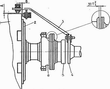
Fig. 16. Centering diagram of the D-180 engine of the T-170 bulldozer. Check the position of the crankshaft axis relative to the axis of the upper shaft of the T-170 gearbox (axial displacement no more than 0.3 mm, transfer no more than 0.7 mm). When checking, use a rigid device, which should be secured to the flange of the upper shaft of the T-170 tractor gearbox with coupling 5 disconnected. Use bolts to set dimensions A and B at the top point of the flywheel to 1-1.5 mm, make a mark and, turning the flywheel and flange with the device, measure dimensions A and B in the next three positions every 90°. The difference in measurements at four points of size A is allowed no more than 0.6 mm, size B - no more than 0.7 mm. Adjust using gaskets installed under the supports of the D-180 diesel engine. The maximum thickness of a set of gaskets under each diesel engine support is no more than 18 mm. When the thickness of the gasket set is more than 10 mm, use gaskets 10 mm thick with welding of the gaskets to the side members. It is also necessary to check the centering of the diesel engine size 31+2 mm when replacing the gearbox or clutch of the T-170 tractor. Adjusting the gaps in the gas distribution mechanism of the D-180 engine of the T-170 bulldozer Adjust the gaps on a warm diesel engine. Before adjustment, tighten the nuts securing the cylinder heads (tightening torque for large nuts is 300-400 Nm (30-40 kg/cm), small nuts 180-240 Km (18-24 kg/cm), as well as the nuts securing the rocker arm shaft struts, torque 160- 200 Nm (16-20 kg/cm) Checking and adjusting the clearances is carried out in the following sequence: Set the decompressor lever to the lower position (for a diesel engine with ESSP - to the clockwise position (to the right) until it stops) and turn the diesel crankshaft D- 180, setting the piston of the first cylinder according to the marks on the flywheel to the top dead center corresponding to the end of the compression stroke. Set the decompressor lever to its original position and use a feeler gauge to check the gap between the rocker arm striker and the end of the valve rod in the first, second, third and sixth valves (normal gap 0 ,25-033 mm). If it is necessary to adjust the gap, you should loosen the lock nut of the adjusting screw on the rocker arm of the valve (Fig. 17) and use a screwdriver to set the adjusting screw to a position in which the 0.3 mm feeler gauge will fit tightly into the gap between the rocker arm striker and end of the valve stem. Tighten the locknut and check the clearance again. Fig. 17 Check the gap between the rocker arm and the tip of the decompressor rod at the first and third valves of the D-180 diesel engine of the T-170 bulldozer. The gap should be at least 0.5 mm, and when the decompressor is turned on, the valve stroke should be 0.7-2.5 mm.
The gap is adjusted by rotating the tip of the rod with the locknut loosened. After adjustment, tighten the locknut and check the valve clearance and stroke again. The valve stroke is measured by an indicator. If there is no indicator, you should set the decompressor lever to the lower position (for a diesel engine with ESSP - to the clockwise (to the right) position until it stops, and use a crowbar to lift the short arm of the rocker arm until the valve stops in the piston. In this position, the gap between the rocker arm and the tip of the engine decompressor rod D-180 of the T-170 bulldozer must be at least 0.5 mm. Rotate the crankshaft one turn and adjust the gap between the rocker arm striker and the end of the valve stem at the fourth, fifth, seventh and eighth valves and the gap between the rocker arm and the tip of the decompressor rod at fifth and seventh. Adjusting the fuel pump of the D-180 engine The D-180 fuel pump, regulator and nozzle are factory-adjusted fuel equipment mechanisms, therefore, they must be disassembled and adjusted by qualified mechanics in specially equipped workshops. Checking the fuel supply advance angle. Disconnect from pump high pressure pipe and screw the torque scope onto the section of the first cylinder. Remove the middle panel and top cover of the T-170 clutch housing to observe the markings on the outer cylindrical surface of the flywheel and the indicator on the clutch flywheel housing. Set the decompressor lever in the lower position (for a diesel engine with ESSP - in the clockwise position (to the right) until it stops) and using the crank handle to turn the crankshaft of the starting engine, rotate the crankshaft of the D-180 diesel engine until air bubbles are completely removed from the momentoscope tube (on In a tractor with an ESSP, a handle located in the spare parts is used to turn the diesel crankshaft. Removing the fuel pump with regulator from the D-180 diesel engine and installing them Close the fuel tank pass-through valve. Disconnect the high-pressure fuel lines from the fuel pump sections, the fuel supply pipe to the fuel priming pump, the fuel inlet and outlet pipes from the fine fuel filter and the fuel line from the fuel priming pump, and the rod of the fuel supply control lever. Close the openings of the disconnected tubes and fittings with safety plugs. Unscrew the bolts securing the regulator housing to the diesel engine bolt and to the timing gear housing. Suspend the fuel pump with a lift. Pull the pump towards you, remove the regulator body from the mounting pins, move the pump to the left and remove it from the diesel engine. To correctly install the fuel pump of the D-180 engine, remove the inspection hatch cover on the timing gear housing. Rotate the diesel crankshaft until the tooth with mark “C” of the small camshaft gear appears in the housing hatch. Position the regulator shaft drive gear so that the tooth cavity marked “C” coincides when installing the pump with the tooth marked “C” of the small camshaft gear. The remaining assembly operations are in the reverse order. Adjusting the D-180 diesel injectors of the T-170 bulldozer D-180 injectors are subject to testing for injection start pressure and fuel atomization quality. To do this, remove the nozzle from the D-180 diesel engine, clean it of dirt and install it on a special stand. For a correctly adjusted nozzle of the D-180 engine of the T-170 bulldozer, the fuel injection start pressure should be: 21 MPa (21 kgf/cm2). If fuel is supplied through the injector being tested earlier (later), it is necessary to adjust it, unscrew the cap, loosen the lock nut of the adjusting screw and, turning it with a special screwdriver, adjust the spring tension. When the adjusting screw is screwed in, the injection start pressure increases, and when unscrewed, it decreases. Once you have finished adjusting, tighten the locknut and install the cap. The quality of fuel atomization should be checked at a frequency of 60-80 injections per minute. The beginning and end of the injection must be clear, the fuel must be supplied from all five holes finely atomized to a mist-like state. If the fuel comes out of a washed and cleared nozzle in the form of a stream, or thickening, leakage, and droplets are observed in the mass of mist-like fuel, then the nozzle is not suitable for operation and must be replaced. It is allowed to check and adjust D-180 injectors using a reference injector. To do this, connect the injector being tested and the reference injector to the fuel pump section through a tee. (In this case, the remaining D-180 nozzles must be disconnected from the pump sections). Set the fuel supply control lever to the maximum flow position and, turning the diesel crankshaft with the starting engine, pump fuel through the nozzle (on a tractor with ESSP, turn the crankshaft using a handle from a spare parts kit). A correctly adjusted injector should inject fuel at the same time as the reference one. Adjusting the engine control drives D-180 Drive the fuel supply control lever D-180 - disconnect the rod from the lever - set the fuel control lever to the “Up all the way” position, and the lever back all the way; — adjust the length of the rod until the holes in the rod fork and the lever are aligned and then, shortening the rod by (5±2 mm), connect it to the lever. Check the fixation of the fuel supply control lever D-180 in the maximum rotation speed position (the lever position is “Top all the way”). When you press the pedal all the way, the lever should not move. If necessary, adjust the accelerator brake with the screw, screwing it in to the minimum force sufficient to hold the lever. Adjusting the drive of the diesel fuel supply control pedal D-180: — disconnect the spring from the hook and the rod from the lever; — move the rod forward and set the outer lever of the fuel pump regulator to the minimum speed position; — set the pedal down all the way; — with the adjuster lever and pedal in the established positions, connect the rod. If the size from the floor to the extreme point of the pedal is less than 170 mm, repeat the adjustment by connecting the rod to the hole. Connect the spring.
_______________________________________________________________________________________
_______________________________________________________________________________________
_______________________________________________________________________________________
_______________________________________________________________________________________
- 970 Elite
- TLB 860
- Cat 422
- Cat 428
- Cat 434
- Cat 444
- 3 CX Super
- 4 CX
- 5 CX
- WZ30-25
- XT860/XT870
_______________________________________________________________________________________
- WB 97S
- WB 93R
- Hyundai H940S
- B110
- B115
- Hidromek HMK 102B
- Hidromek HMK 62SS
_______________________________________________________________________________________
- Mobile cranes
- Cranes manipulators
- Motor graders DZ-122,143
- Excavator EK-14
- Kamaz truck repair
- MAZ truck repair
- TL 65
- TL 120
- TL 310
- Cat 914
- Cat 924
- Caterpillar 950
- Caterpillar 966
_______________________________________________________________________________________
- LW500F
- ZL30G
- ZL50G
- LW321F
- XGMA XG932
- XGMA XG955
- Design of Terex, Komatsu, Cat loaders
- ZW250
- ZW310
- ZW220
- ZW180
- W130
- W170
- W190
- W270
- L34
- Adjusting the D-180 engine
- Transmission T-170
- Assembly of gearboxes T-170, T-130
- Adjusting the T-170 clutch
- Hydraulic and mounted systems T-170
- Main gear T-170, T-130
- Diesel injection pump D-160
- Servo mechanism of clutch T-130, T-170
- Onboard clutches T-130
- Final drive of the T-130 tractor
- Rotation control mechanism T-130
- Hydromechanical transmission TO-18/TO-18B
- Hydraulic system GMP TO-18/TO-18B Amkodor
- Hydraulic system TO-18
- Hydraulic system components TO-18/TO-18B Amkodor
_______________________________________________________________________________________
- Design of rack and pinion hydraulic cylinders
- Types of positive displacement hydraulic pumps
- Rotary screw pumps - Design and operating principle
- Characteristics and design of gear pumps
- Pump control diagram in a closed hydraulic system
- Hydraulic distributor device with proportional control
- Hydraulic systems of special equipment - operation and maintenance
- Application of hydrostatic transmissions for special equipment
- Application of cartridge electrically controlled valves
- Design and diagrams of cartridge plug-in hydraulic valves
- Characteristics of Screw-in Hydraulic Cartridge Valves
- Sequence valve and pressure reducing valve operating diagrams
- Variable displacement hydraulic pump regulator
- Load Sending System for Variable Pumps
- Hydraulic distributors - Control systems
- Control diagrams for working hydraulic units of special equipment