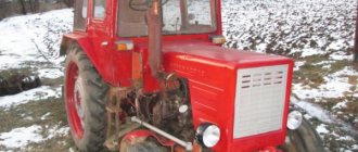
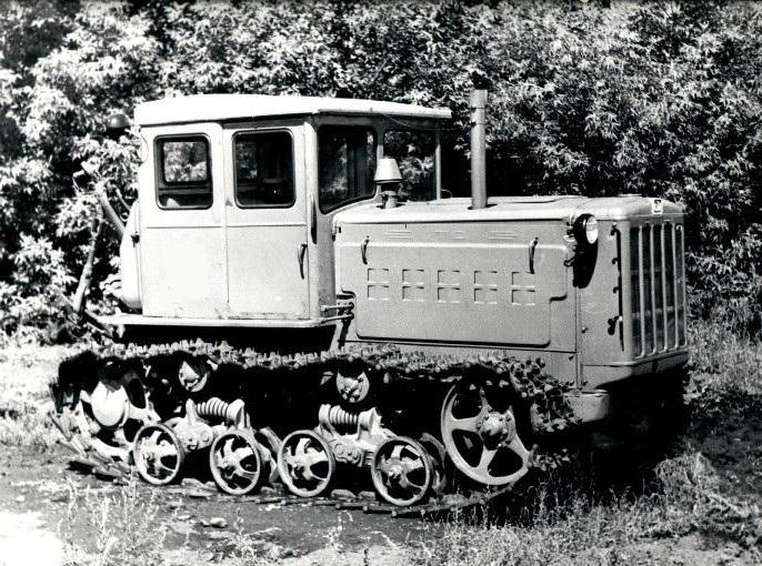
The Soviet tracked tractor DT-54 (photos are presented on the page) was created in 1949 at a plant in Kharkov. Serial production of the new agricultural machine was launched there. The DT-54 tractor was produced at KhTZ from 1949 to 1961. Another production was opened at the Stalingrad Tractor Plant, where the machine was produced in approximately the same quantity. In the difficult post-war years, USSR agriculture needed technology. The third serial production was organized at the Altai plant, where the DT-54 tractor was produced from 1952 to 1979. A total of 957,900 units were built across the three plants.
A little history
The DT-54 tractor was a successful development based on the outdated AZKhTZ-NATI model, with many new technical solutions and the use of modern technologies. The design of the machine is quite perfect, the diesel engine is economical, the consumption of oil and diesel fuel does not exceed the lower limits of the established operating standards. The engine was the first to use a centrifugal oil purification system through the use of special chambers in the crankpins of the crankshaft.
An oil centrifuge combined with a standard filter worked on the same principle. The plug for draining used oil from the crankcase was a powerful magnet that collected small particles of metal. All these measures significantly extended the service life of the engine.
The tractor was equipped with a dual-range gearbox, through which ten more were added to the five main gears. This device made it possible to select the optimal load on the engine and helped maintain its performance.
The rear axle was equipped with separate control of rotary couplings and brakes, which greatly facilitated control of the vehicle. Before 1956, there was no such division. At the same time, band-type brakes operating in both directions were introduced. The efficiency of the slowing mechanisms has increased significantly.
§ 8.
Cylinder head, its cap and breather of diesel engine D-54A
From above, the crankcase is closed with a cast-iron head common to all cylinders (Fig. 15), which is put on studs 3 (Fig. 13), screwed into the crankcase, and secured with nuts. To create a tight connection between the crankcase and the head, a gasket made of asbestos steel is installed.
Opposite each cylinder in the lower wall of the head (Fig. 15) two dish-shaped recesses are made. In the middle of each recess there is a cylindrical hole, the edges of which are beveled at an angle of 45°. The beveled edges serve as support bands for the valves.
The 14 openings of the intake valves of the first and second, as well as the third and fourth cylinders are connected in pairs inside the head into channels 4, which extend outward on the right side wall of the head. The inlet pipe is attached to the platforms at channels 4 on studs 5.
The exhaust valve openings 13 extend inside the head into separate channels 17, which exit outward on the left side wall of the head. The exhaust pipe is attached to the platforms at the exhaust channels on eight studs 18.
The diameters of holes 13 and 14 are the same. Above each of them there is a vertical channel into which a cast iron valve guide sleeve 6 is pressed. On the right side inside the head, opposite each cylinder, there is a cast vortex chamber 26 (Fig. 9), which has a spherical shape.
A nozzle is inserted into the stepped hole 3 (Fig. 15) of each vortex chamber and secured to the head with two studs 2 with nuts.
The cavity inside the cylinder head is called the water jacket. To connect the water jackets of the head and the crankcase, there are fourteen holes in the lower wall of the head, coinciding with the corresponding holes in the crankcase.
The water cooling the diesel engine exits from the water jacket of the head through hole 11 through the pipe into the radiator. The pipe is bolted to the mating plane of hole 11.
A cover with a pipe is bolted to the mating plane of hole 19 on the rear wall of the head, through which water from the water jacket of the starting engine enters the water jacket of the diesel cylinder head.
To seal, cardboard gaskets are placed between the flanges of the nozzles and the mating surfaces of the head.
Eight through holes 9 are intended for the passage of pusher rods. In the left front part of the head there is a channel 15 for supplying oil to the valve mechanism.
Rice. 15. Cylinder head: a - top view; b - bottom view; 1 — platform for mounting the generator bracket; 2 - Injector mounting pin; 3 — hole for the nozzle; 2—karal; 5— stud for fastening the intake pipe; 6 — guide sleeve; 7 — stud for fastening the rocker shaft stand; 8 — hole for the head mounting pin; 9 — hole for the pusher rod: 10 — recess for collecting oil; 11 — hole for draining water from the cylinder head into the radiator; 12 — threaded hole for the eye: 13 — exhaust valve hole; 14 — intake valve hole; 15 — channel for supplying oil to the rocker shaft support; 16 — channel connecting the water jacket of the cylinder head with the water jacket of the crankcase: 17 — exhaust channel; 18 — stud for fastening the exhaust pipe; 19—hole through which water flows from the water jacket of the starting engine into the water jacket of the diesel cylinder head.
To drain the oil that accumulates in the recesses 10, special drainage channels are made that communicate with the pusher rod box.
There are twelve threaded holes on the top surface of the cylinder head. Pins 7 are screwed into four holes for fastening the rocker arm shaft posts. Six holes are used to secure the cap body with bolts. Eyes (bolts with eyes instead of heads) are screwed into two holes 12. Eyes are necessary for lifting the assembled diesel engine or removing the cylinder head.
In front of the right side of the head there is a machined plane to which the generator bracket is bolted.
To protect against damage and contamination, the valve mechanism parts located on the cylinder head are closed with a cap with covers (Fig. 16).
The cast iron body of 1 cap is secured to the head with bolts. To prevent oil leakage, a gasket is installed between the bottom plane of the cap and the head.
Breather 6 is attached to the jumper of the cap body with two studs.
The top of the cap body is closed with two covers 4. Each cover is secured to the body with two nuts 3. To seal, gaskets are installed between the caps and the cap body. Removable cap covers allow you to check the condition of the valve mechanism parts and adjust the valve clearances.
The breather is designed to equalize the pressure in the diesel crankcase with atmospheric pressure. For this purpose, it connects the internal cavity of the diesel crankcase with the atmosphere through the internal cavity of the cap and the box of pusher rods.
When a diesel engine is running, gases from the cavity above the piston partially break into the crankcase, increasing the pressure in it. This phenomenon increases significantly when the piston rings wear out.
Rice. 16. Cylinder head cap: 1 - cap body: 2 - hole; 3 — nut for fastening the cover; 4 — cover; 5 - gasket; 6 — breather.
Rice. 17. Diesel breather:
1 — housing flange; 2 - body; 3 - packing; 4 — plate with holes; 5 - spring ring.
An increase in pressure in the crankcase is unacceptable, since gases breaking through the seals break through them and an oil leak appears. In addition, increased pressure in the diesel crankcase leads to oil burnout.
The cast-iron body 2 (Fig. 17) of the breather is attached by means of flange 1 to the jumper of the hood body. A cardboard gasket 5 is placed between the flange and the jumper for sealing (Fig. 16).
Inside the breather body, between two steel round plates 4 (Fig. 17) with a large number of small holes, there is a packing 3 made of steel wire.
When gases escape, the packing, preventing oil from splashing from the breather, is wetted with oil dust, which is carried away by gases from the diesel crankcase. The oil-moistened packing acts as a filter that protects the internal cavity of the diesel crankcase from dust.
content .. 1 2 3 7 ..
Flaws
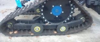
One of the disadvantages of the DT-54 was the friction of the track tracks on the final drive housing. In this regard, special intermediate pads were installed, which simultaneously stabilized the direction of travel of the tracks and played the role of a gasket between the caterpillar and the crankcase. These innovations were also applied in 1956. At the same time, the towing device was improved, the bracket of which was lengthened, reinforced with a transverse strip, and the earring was made wider to accommodate a finger of larger diameter. Now any towed device was securely attached to the tractor.
Basic problems and solutions
Farmers particularly appreciated the ease of maintenance in the DT-54. Soviet virgin land workers did not have the opportunity to take equipment to a licensed center, as they do now, so the ability to repair and maintain it “on the job” was extremely important.
If the engine did not start, it could say, for example:
- about the low quality of diesel fuel (diesel fuel);
- about lack of lubrication;
- about clogging of the starting device.
In case of strong vibration, it was recommended to pay attention to:
- whether the units are hung correctly;
- Are the diesel and oil levels normal?
- Are the fasteners in order?
The main problems with operation were said:
- about lack of fuel;
- about clogging of parts and clutches;
- about the absence of contacts of wires and switches.
The vast majority of faults could be corrected on site.
Modernization
In 1952, the engine was equipped with a special counter that kept track of the time during which the engine was running. This prevented the tractor from idling or being used for other purposes. The meter was sealed at the beginning of work, and its readings were taken after the end of the working day.
After 1956, the rotation transmission of the crankshaft, which operated peripherally, was improved. Next to the main shaft, connected to the transfer case, an additional splined cylinder rotated, to which a special coupling could be connected, connecting the transmission to the “quasi” gear. The additional attachments that were intended to be used at the moment and which were equipped with their own rotation mechanism were connected to the power take-off shaft.
Normally, power take-off mechanisms were not included in the package, but they could be installed upon a separate request from the buyer. This addition was expensive, but consumers understood how useful this device was and did not consider the costs. At the same time, it was possible to install a drive pulley on the tractor, which also made it possible to make power take-off for peripheral equipment, but only through a belt drive.
Maintenance
In the instructions for the car one could find instructions on the need:
- perform an initial run-in without loads to ensure that the tractor parts rub against each other;
- use and promptly change the appropriate motor oils (M-10DM or M-10G2k plus transmission oil Tap-15V);
- preserve the car when not used for a long time (completely clean and lubricate, drain fuel);
- promptly respond to problems with internal combustion engines, without waiting for the situation to worsen.
Tractor DT-54: technical characteristics
The main functions of the DT-54 were complex work with a four or five-section plow. Traction characteristics made it possible to plow land of any density. In addition, the DT-54 tractor could interact with a number of additional trailed devices.
The thrust range of the powerful machine was 1200 - 2850 kg, which made it possible for its wide use. The machine's operating speeds ranged from 3.58 to 7.8 km/h, the transmission had five forward gears and one reverse. The diesel engine at a rated speed of 1300 rpm developed a power of 54 hp, which was enough for any field work.
Scope of application
DT-54 is a general-purpose tractor: it was universal, capable of any agricultural work. With its help they mastered virgin lands:
- planned land plots;
- carried out excavation work;
- plowed the soil with 4- and 5-circuit plows, harrowed;
- sowed the land;
- harvested crops;
- mowed the grass;
- cleared the snow.
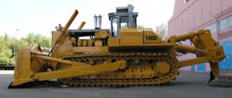
The DT-54 could be used as a bulldozer and towing vehicle. He had a variety of gripping tools and successfully worked in construction and light industry. An obstacle to its introduction into widespread use in this capacity was the caterpillar drive: although it copes well with uncultivated land, such a tractor inevitably destroys the road surface. However, the DT-54 restored many war-damaged cities and built many roads.
Weight and dimensions parameters
- Total weight - 5400 kg.
- Length with trailing mechanism - 3660 mm.
- Height - 2300 mm.
- Width - 1865 mm.
- Ground clearance, ground clearance - 260 mm.
- Center distance - (outer rollers) 1622 mm.
- The track in the middle of the caterpillar track is 1435 mm.
- Specific soil pressure - 0.41 kg/cm2.
- Fuel tank capacity - 185 cm / cu.
Price
For those times, the cost of the DT-54 was low. The tractor became truly widespread, one of the main tools for developing virgin lands, and therefore was purchased by agricultural enterprises on a very large scale.
Restored DT-54s can still be bought today (albeit more as a historical monument than a working machine). Amateur mechanics revive the equipment of those times, replacing worn-out parts with newer ones (from other models), but at the same time trying to maintain the original appearance. Most of these customized tractors are even on the move. The price varies depending on the condition of the internal combustion engine and mechanisms - from 50 to 200 thousand rubles (for comparison, previous and some subsequent models that did not gain such popularity are now presented only in the form of scrap).
Analogs
The DT-54 (except for the DT-54A variation) has no direct analogues. But its design served as the basis for the creation of the next generation of tractors: T-75, T-74, DT-75. They were more powerful, had an improved gearbox, and more efficient internal combustion engines. The DT-75 is still in production, and it is the only one that has surpassed the DT-54 in terms of mass production (more than 2.5 million units).
Despite the fact that the DT-54 is now clearly an outdated vehicle, it remains legendary. Her fans still exist today. There are many monuments to the DT-54 in Russia, and the authorities of Vietnam, where the USSR actively exported its cars, even placed an image of the DT-54 on their banknotes.