Clutch device
In a MAZ car, the clutch is dry, double-disc, friction-type with cylindrical springs located along the periphery. It is installed in a cast iron crankcase. It is designed to briefly separate the engine crankshaft from the gearbox, as well as to smoothly connect them while the car is moving away and during further gear changes.
You need to know how to properly adjust the clutch, i.e. check it, lubricate the drive and release bearing following the lubrication chart. It is necessary to regularly monitor how the clutch housing mounting bolts are tightened to the flywheel housing. The tightening should be 8-10 kgm. This should be done with uniform movements, with a criss-cross sequence. After tightening the bolts, they should be secured by bending the antennae of the locking plates on the edge of the bolt heads.
content .. 41 42 45 ..CLUTCH YaMZ-238N
The clutch of the YaMZ-238N model is a double-disc, dry, friction type, with a peripheral arrangement of cylindrical springs. The YaMZ-238N clutch can be made in a sealed version.
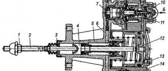
The clutch housing 16 (Fig. 6), stamped from sheet steel, with the pressure disk 19 assembly is installed on the engine flywheel 20, and the driven disks 21 are installed on the splined part of the gearbox input shaft. The front and rear driven discs are not interchangeable and are installed in a specific position, as shown in the figure. The driven clutch discs are clamped by a constant force of twenty-eight cylindrical pressure springs 17 between the engine flywheel, the middle and pressure discs. Thermal insulating gaskets 18 are placed under the springs on the pressure disk side. The pressure and middle drive disks are connected to the flywheel with four spikes located on the outer surface of the disks. When clamped, the driven disks transmit engine torque to the transmission input shaft.
The clutch is released by clutch 11. The clutch with the bearing, moving towards the engine, moves the pressure plate away from the driven disk, transmitting force through four rigid release levers 5. The working stroke of the clutch release clutch, taking into account free play, must be at least 18.2 mm (size “D”). The amount of free play is regulated by the clutch release mechanism. The thrust ring of the pull-out levers moves towards the gearbox by 27 mm due to the permissible wear of the friction linings.
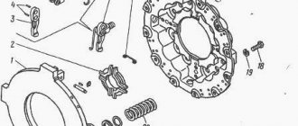
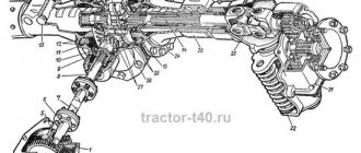
Fig.6. Clutch YaMZ - 238N:
1 – rod; 2 – ring; 3 – disc spring; 4 – bar; 5 – pull lever; 6 – pull lever fork; 7 – adjusting nut; 8 – spacer plate: 9 – locking plate; 10 – spring loop of the pull-out lever; 11 – clutch release clutch with bearing; 12 – lubricant supply hose to the clutch release clutch; 13 – clutch release fork; 14 – thrust ring of pull-out levers; 15 – clutch release fork shaft; 16 – clutch casing; 17 – pressure spring; 18 – thermal insulating gasket; 19 – pressure disk; 20 – flywheel; 21 – driven disks; 22 – middle drive disk; 23 – release spring; D – minimum stroke of the release clutch.
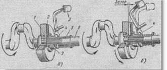
Guaranteed clearances between the driven disks and the friction surfaces of the flywheel, middle drive and pressure disks when the clutch is disengaged as the linings wear are ensured by a mechanism for automatically adjusting the withdrawal of the middle disk, which consists of rods 1 fixed in each of the four spikes of the middle drive disk, split rings 2, to move along the rod which requires a certain force, thrust bars 4, which are bolted to the flywheel with the clutch casing, and disc springs 3 installed on the rod between ring 2 and bar 4.
When the clutch is disengaged, the pressure plate 19 moves back at least 2 mm and releases the rear driven disk
- The middle drive disk 22, under the action of the spring 23, also moves back, until the ring 2 stops in the bar 4 through a disc spring, by an amount of 1.2 ± 0.1 mm, freeing the front driven disk.
As the clutch friction linings wear out, the middle drive disk, under the action of the pressure springs of the pressure disk, moves to the flywheel, the rings 2 rest against the clutch housing, moving along the rods 1 and maintaining the size between the rings and the disc springs.
When installing a clutch with a mechanism for automatically adjusting the release of the middle disk onto the flywheel, observe the following procedure:
Install the front driven disk.
- Install the middle drive disk with rods.
- Install the rear driven disk.
- Install the pressure plate and housing assembly, securing it to the flywheel with eight short bolts.
- Place split rings 2 onto rods 1 until they stop at the clutch housing.
- Place the four disc springs with the convex side facing the split rings.
- Install four thrust bars and secure them with the housing to the flywheel using eight long bolts.
After installing the clutch on the flywheel, make sure that the rings on the rods rest against the housing, providing a gap of 1.2 ± 0.1 mm between the rings and the disc springs when the clutch is engaged.
When the driven disc linings wear out, the end of the clutch release clutch will rest against the end of the gearbox input shaft bearing cover; in this case, replace the worn linings of the driven discs with new ones.
Lack of free play of the clutch will lead to failure of the pressure bearing and increased slipping of the driven discs. The free play of the clutch release clutch (dimension “A”) is adjusted by changing the length of the release mechanism rod or the length of the amplifier cylinder rod, depending on the design of the clutch release mechanism in accordance with the vehicle operating instructions.
ATTENTION! ADJUSTING THE FREE STROKE OF THE CLUTCH RELEASE CLUTCH WITH THE ADJUSTING NUTS OF THE EXTRACTION LEVERS IS STRICTLY PROHIBITED.
After adjustments, check the clutch for missing
"conduct"; Carry out this check with the engine running with first gear engaged and the clutch disengaged.
ADJUSTING THE POSITION OF THE STRAP RING OF THE PULL ARMS
When assembling the pressure plate and housing assembly, adjust the position of the thrust ring. This adjustment is made in a device having an installation dimension of 27 ± 0.1 mm (Fig. 7) with adjusting nuts 6 pull-out levers with the casing and pressure disk in a fixed position. By adjusting, ensure dimension “B” is equal to 64 ± 0.1 mm, while the thrust surfaces of all four release levers 5 must simultaneously touch the thrust ring 4. A misalignment of the thrust ring will lead to uneven release of the pressure plate when the clutch is disengaged or its abnormal operation.
After adjusting the position of the thrust ring using the adjusting nuts 6, install the locking 7 and support plates 8 of the adjusting nuts. Tighten all eight bolts securing the locking and support plates, installing spring washers under the bolt heads.
Rice. 7. Device for assembling the pressure disk with housing assembly:
1 – stand; 2 – guide pin; 3 – casing mounting bolt; 4 – thrust ring of pull-out levers; 5 – pull lever; 6 – adjusting nut; 7 – locking plate; 8 – support plate; 9 – pressure plate
In the case of using a pressure plate with a casing complete with driven disks after repair, on which friction linings with a thickness of 4.15 mm are installed, when adjusting the position of the thrust ring, set dimension “B” to 67 ± 0.1 mm.
CLUTCH OPERATION
In order to prevent increased wear of clutch parts and possible failures during vehicle operation, ensure the following:
- Move away at the minimum possible speed of the engine crankshaft; in this case, the gearbox must be in 1st or 2nd gear, depending on the vehicle load and road conditions.
- Regulating the speed of the vehicle by slipping the clutch is not allowed.
- After starting the car, do not keep your foot on the clutch pedal.
- Do not operate a vehicle with a faulty and unadjusted clutch release drive. Adjust the clutch release drive on the vehicle in accordance with the instructions in the vehicle's operating manual.
- When operating cars and other vehicles in difficult road conditions, especially after repeated starts and overcoming traffic obstacles, check for free play of the clutch.
content .. 41 42 45 ..
Adjustment steps
- To fully adjust the clutch, you first need to adjust how far back the middle drive plate is. This will ensure the required clearance of the clutch working surfaces. Additionally, it is necessary to adjust the gap at the end of the valve body cover and its adjusting nut, then adjust the operation of the clutch pedal.
- Next, you need to determine how to remove the middle drive disk, first removing the hatch covers from the clutch housing and flywheel. To do this, you need to engage the clutch and set the gearbox to neutral. Then you should turn the engine flywheel, while screwing the four adjusting screws into the middle drive plate all the way. First, you need to unscrew the locknuts on the screws.
- Without stopping turning the flywheel, you need to unscrew the adjustment screws one turn and secure them with locknuts. When tightening the lock nuts, you should not apply enormous force, and it is best to hold the adjusting screw to avoid shifting the adjusted gap.
- We measure the gap between the end of the rear cover of the valve body and the adjusting nut, which should be from 3.3 mm to 3.7 mm. It is necessary to control the size of the gap after each maintenance-2. This can be adjusted by loosening the locknut and setting the required gap size. After this, you need to tighten the locknut without violating the established gap.
- The next step is how to adjust the clutch pedal. To do this, you will need a ruler, with which, after bleeding air from the pneumatic system, you will need to measure the pedal stroke. It should correspond to 34-43 mm. Free movement control should be carried out after each maintenance-1. Before doing this, you must make sure that the previously established gap is normal.
- To regulate the free travel of the pedal, it is necessary to disconnect the double-arm pedal drive lever from the valve stem fork and the clutch cylinder rod fork. At the same time, move the cylinder piston to the very bottom, and move the lower edge of the double-armed lever in the opposite direction until it stops. It is necessary to check that the holes of the cylinder rod fork and the lever are not aligned by approximately 50%. If there is a deviation upward or downward, it is necessary to bring it to the required size by rotating the cylinder rod.
- The final stage of how to adjust the clutch on a MAZ will be connecting the lever and all disconnected elements, adjusting the distance between the fork holes by rotating the forks themselves. This will be difficult to do if the friction linings of the discs are heavily worn. In this case, you will need to move the double-arm lever by 1 slot counterclockwise. Then readjust the clutch pedal travel.
MAZ clutch and part device
The MAZ clutch is a double-disc friction type device. It has springs that are located peripherally. The MAZ clutch device also includes discs. The elements are made of durable materials. The MAZ clutch is installed in a crankcase made of strong cast iron. The leading parts of the mechanism are the MAZ clutch disc (middle and pressure) and the MAZ flywheel. AvtoResurs LLC offers a closer look in a number of articles on how to adjust the MAZ clutch and repair the part. However, today we will tell you what the MAZ clutch device consists of and how the MAZ clutch drive works.
1. The MAZ clutch has a complex structure
Let's look at the Minsk Automobile Plant truck model 5335. Let's carefully study the MAZ clutch design. So, the mechanism includes a huge number of elements, for example:
- Release lever and springs;
- MAZ clutch fork, rings, rod;
- Nut, plates, MAZ clutches;
- Fork shaft lever, pin, MAZ clutch cover;
- Gaskets, MAZ clutch disc, flywheel and hubs.
These components are the main ones in the design of MAZ spare parts. Also, all mechanisms are strong and resistant to heavy loads. Therefore, the MAZ clutch, as well as the MAZ clutch drive, last a long time and rarely fail. Cast iron is mainly used for the manufacture of elements from the MAZ clutch device. Let's take a closer look at each part of the part being studied. The MAZ clutch disc (pressure and drive) is cast from durable cast iron.
Has spikes that attach to the truck's flywheel. Thus, the MAZ clutch is a very strong connection, which makes it easy to move the MAZ clutch disc. Also in this case, torque is transmitted to an element such as the MAZ clutch disc from the flywheel. A frictional force arises. The MAZ clutch has several friction attachments that contain the MAZ clutch disc. Therefore, during the operation of the elements, a frictional force occurs. That is, torque is transmitted from the surface of the friction linings, discs and flywheel to the MAZ gearbox. Note that the MAZ clutch drive of a modern truck does not include discs. 2. MAZ clutch is reliable and strong
We continue to consider the MAZ clutch device.
To prevent heating of the springs, which most often occurs when the truck slips for a long time, a pressed cardboard gasket is adjusted under the springs of the MAZ spare parts. The MAZ clutch disc is not interchangeable. The elements are mounted on the MAZ input shaft, that is, on its splines. The MAZ clutch also includes a hub, a disc with linings and a vibration damper.
As a rule, MAZ hubs and MAZ clutch discs are made of steel. The MAZ clutch is protected from the harmful effects of various vibrations when the vehicle is moving thanks to a special damper. These vibrations are most often transmitted from the truck engine shaft. In addition, the MAZ clutch device is reliably protected by a failure absorber when the mechanism is engaged. The damper also allows the gearbox gears to operate more smoothly.
The MAZ clutch disc is not included in the drive to disable the mechanism in question. So the MAZ clutch device when turned off is approximately the following:
- Pins, rods and pedals;
- MAZ clutch levers, springs and forks;
- Cylinder rod, cylinders and retaining ring;
- Gap and valve.
Thus, the MAZ clutch drive is equipped with a pneumatic booster. In general, the part is strong and practically does not break. However, the MAZ clutch drive, like any element of a truck, requires regular inspection. The rods and valves are connected in series. Thus, the mechanical clutch drive is also equipped with a working cylinder of the amplifier. The element is installed in parallel. The MAZ clutch drive includes in its MAZ clutch device and a double-arm lever, which is connected to the cylinder and valve rod. As you can see, the MAZ clutch diagram is simple. However, before adjusting the units, it is necessary to carefully study their design. If we consider the MAZ clutch drive, the element is adjusted in two ways.
That is, by adjusting the free play of the MAZ clutch pedal. In addition, the MAZ clutch drive is regulated by the gap between the ring (retaining ring) and the end of the valve body cover. The MAZ clutch disc does not require special care.
Inspect the part regularly to ensure timely repair of breakdowns. The MAZ clutch drive is also unpretentious.
Just periodically check the free play of the pedal and clutch bearing.
The MAZ clutch device also contains a drive. We recommend that you monitor the condition of this item more carefully. Subscribe to our channels on social networks twitter, facebook, contact, google+.