Adjusting the differential bearings.
The axial clearance in the differential bearings should be checked after 3000 hours of operation during the next maintenance. The check is carried out by moving the differential using a mounting blade or by hand. Before checking, tighten the bolts of the housing flanges and the bridge cover. If the differential movement is noticeable by hand, then the bearings need to be adjusted. For example, the axial clearance is 0.25 mm, then the thickness of the gasket package between the flanges of the housing and the bridge cover must be reduced by removing a 0.2 mm thick gasket. If the axial movement is 0.3 - 0.4 mm, two shims of 0.2 mm thickness should be removed. The preload in the differential bearings should not exceed 0.1 mm. After adjustment, you need to monitor the heating of the housings on transport gears (temperatures above 60°C indicate overtightening of the bearings).
Adjusting the gear engagement of the main gear.
It is not recommended to adjust the engagement of the main gear gears during operation even with very noticeable wear of the teeth, since their wear practically does not interfere with the normal operation of the transmission. This is explained by the fact that satisfactory tooth contact is obtained only in one relative position of the drive and driven gears, when the generatrix of the initial cones is common to both gears. Trying to reduce the side play in worn gears can lead to failures due to poor contact in the teeth. However, if increased lateral clearance (1.2 - 1.5 mm) is found in a new gear, this indicates that it has been incorrectly assembled and the clearance should be adjusted to normal limits. Adjustment of the gearing is also necessary in cases of replacing bearings, axle housing, differential housings, and drive gear housing. The position of the driven gear is regulated by spacers, which are placed between the bearing cups and the housing, moving from under one cup to another. The position of the drive gear and the lateral clearance in the mesh are adjusted using shims, which are placed on the glass of the gearbox input shaft. The side clearance in the teeth depends on the axial clearance of the drive gear and differential bearings, so before checking the gearing, you should make sure that there are no gaps in the bearings.
Rice. 1. Contact patch of the bevel gear teeth of the main gear.
a - correct contact patch; b - contact at the top of the tooth; c — contact at the base of the tooth; g - contact at the narrow end of the tooth; d - contact at the wide end of the tooth
After adjusting the side clearance, check the contact patch of the teeth. With proper contact, the entire length of the tooth is involved in the work under load. Several teeth of the driven gear are covered with a thin layer of thickly diluted paint (red lead) and the drive gear is turned several times in both directions. With correct contact, the spot (Fig. 1, a) should occupy at least 50% of the length of the tooth, have a width of at least 50% of the working height of the tooth and be located closer to the narrow end of the tooth (to the top of the pitch cone). If the contact is incorrect, it is necessary to change the position of the drive or driven gear: if the contact is at the top of the tooth (Fig. 1, b), then the drive gear should be brought closer to the driven gear by changing the thickness of the gaskets on the input shaft of the gearbox; when there is contact at the base of the tooth (Fig. 1, c), the drive gear must be moved away from the driven gear; if the spot is located closer to the narrow end of the tooth (Fig. 1, d), move the driven gear away from the driving gear; When the contact patch is located at the wide end of the tooth (Fig. 1, e), bring the driven gear closer to the drive gear. If the teeth of the final drive gears are significantly worn, it is recommended to swap them. In this case, the driving and driven gears must be rearranged simultaneously. Install the axle sleeves as far as they will go into the rear axle. Lubricate the gaskets with sealant before installation. Install the sealing collars with their working edges towards the bearings. When installing the sleeve cover, put 40 - 50 g of solid oil into the bearing.
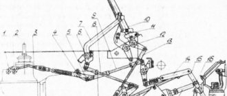
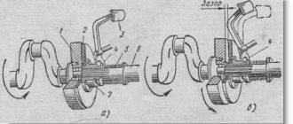
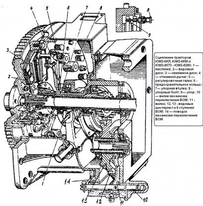
The clutch of the YuMZ family of tractors is dual-flow (main and PTO). Two driven discs with friction linings differ in hub sizes. The driven disk of the main clutch 10 (Fig. 1, a) is put on the splines of shaft 6, passed through the tubular shaft 18 and transmitting rotation to the gearbox, and the driven disk 12 of the PTO clutch is on the splines of the tubular shaft 18. Pressure disks 11 and 13 are tightened by six springs 4, put on rods 3.
When the main clutch is turned off, the pressure disks 11 and 13, moving, release only the driven disk 10, as a result of which the transmission of rotation to the shaft 6 stops and the tractor stops, and the disk 12, remaining clamped by the springs 4, continues to transmit rotation to the PTO.
The joint movement of disks 11, 12 and 13 continues until disk 11, with its stops 26, reaches three bolts 24 screwed into the clutch housing. If you continue to press the pedal after this, then only one disk 13 will move back, overcoming the resistance of not only the springs 5, but also the springs 4. Thus, the driven disk 12 will be released and the transmission of rotation to the PTO will stop.
The pedal position corresponding to disengaging the main clutch without disengaging the PTO is fixed. The pedal can move until the locking roller 28 (Fig. 1, b), rotated by rod 29 and lever 27, rests its flat against the latch on shaft 32. This position corresponds to the release of the driven disk 10.
If you need to disengage the PTO clutch, then by pressing pedal 34, pull back the latch and release the locking roller 28, which allows you to press pedal 30 all the way. In the upper position, pedal 30 is held by the spring of the servo mechanism.
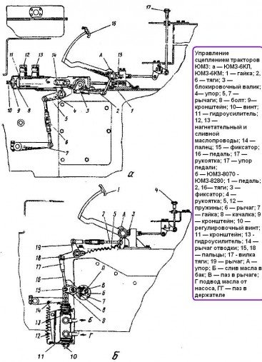
On the latest models of tractors of the YuMZ family, the clutch, unlike the one discussed above, has an additional two-speed PTO switch (Fig. 2) and a mechanical control drive with hydraulic booster (Fig. 3).
Clutch adjustments
In the clutch of tractors YuMZ-6L, YuMZ-6M
make the following adjustments;
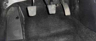
Free play of the pedal (the gap between the thrust bushing and the release levers);
The pedal travels all the way to the latch, ensuring complete disengagement of the main clutch;
The gap between the thrust bolts and the front pressure plate, which ensures disengagement of the main PTO drive without disengaging the clutch.
The clutches are adjusted in the following sequence.
Set the free play of the clutch pedal within 30+5 mm by changing the rod length. To increase free play, the rod should be lengthened, and to decrease it, it should be shortened.
Check the pedal travel all the way to the latch, which should be 145 ± 5 mm. If necessary, the pedal stroke is adjusted by the locking roller drive rod; to increase the pedal stroke, the rod is shortened, and to decrease it, the rod is lengthened.
The servo amplifier mechanism is adjusted so as to ensure minimal force on the pedal when the clutch is disengaged and a clear return of the pedal to its original position. Adjustment is made by moving the servo amplifier bracket along the oval holes. The servo amplifier springs are pressed with a thrust screw, for which it is unscrewed by 3 - 8 mm.
Remove the cover of the lower hatch in the clutch housing and tighten the bolts 24 until they stop (see Fig. 1), and then unscrew each of them 716 turns (seven clicks of the locking device).
In case of severe wear of the driven clutch discs, its adjustment is carried out by changing the position of the release levers while simultaneously changing the length of the main rod. The adjustment is performed in the following sequence:
Remove the cover of the lower clutch hatch;
Adjust the release levers using nuts to ensure a size of 73.5 mm between the end of the PTO driven disk hub and the cams of the release levers;
Change the length of the main rod and set a gap of 3 - 4 mm between the thrust bushing and the release levers. The difference in clearances for the three levers should not exceed 0.3 mm. After the clearance is finally established, the nuts of the release levers are pinned;
Screw in bolts 24 until they stop, and then release each of them 7/6 of a turn.
When a new or repaired (with replacement of discs) clutch operates, the discs intensively wear in and the initial adjustment is disrupted. During the running-in period (approximately 30 hours of tractor operation), the gap between the lift sleeve and the release levers is allowed to be 3+1 mm, and the difference in gaps for the three release levers should not exceed 1.3 mm.
Clutches of tractors YuMZ-6KL, YuMZ-6KM and YuMZ-8070... YuMZ-8280
They differ from each other only in the design and location of the control mechanism. Adjust the clutch after running in the tractor and every 500 operating hours. In the clutch, adjust the gap between the safety ring 6 (see Fig. 2) of the release levers 4 and the thrust sleeve 7 of the release bearing, as well as the gap between the thrust bolts 8 and the stops 9 on the pressure plate 3 of the main clutch.
Tractors YuMZ-6KL, YuMZ-6KM.
Adjustment sequence.
1. Remove the cover of the lower hatch in the clutch housing.
2. Screw in the thrust bolts 8 until they come into contact with the stops 9, and then unscrew each of them seven clicks of the locking device, which corresponds to a gap of 1.75 mm between the thrust bolts and stops 9,
3. Disconnect the rod 6 (see Fig. 3, a) of the clutch control mechanism drive from the release lever 7.
4. Turn lever 7 upward until the release bearing stops against the release lever safety ring, and then release it by 4.5 mm, which corresponds to a gap of 3 - 4 mm between the safety ring and the release bearing thrust bushing.
5. Adjust, without changing the position of lever 7, the length of rod 6 until the holes in the rod coincide with the hole in the lever and connect them.
After significant wear of the clutch discs, restoring the gap between the safety ring of the release levers and the thrust sleeve of the release bearing by changing the length of rod 6 may not be possible. In this case, you need to change the position of the release levers, and then shorten rod 6 and adjust the gap in the indicated order (see paragraphs 4 and 5).
To change the position of the release levers, do the following:
1. Remove the cover of the lower hatch in the clutch housing and unpin the nuts 5 (see Fig. 2) of the release lever rods.
2. Adjust the position of the release levers 4 by rotating the nuts 5 so that the safety ring is at a distance of 83 ± 0.5 mm from the plane of the hub flange of the driven disk 2 of the PTO. After adjustment, the safety ring must be in a plane perpendicular to the axis of rotation, i.e. in a plane parallel to the thrust sleeve 7 of the release bearing. The non-parallelism should not exceed 0.3 mm. Before the final check of parallelism, nuts 5 must be secured with cotter pins.
After replacing the discs or other repairs to the clutch, the position of the release levers 4 must also be adjusted with nuts 5 so that the distance between the plane of the hub flange of the PTO driven disk 2 and the plane of the safety ring 6 is equal to 83 ± 0.05 mm
Adjusting the clutch control mechanism.
In case of repair or replacement of parts of the clutch control mechanism, it must be adjusted in this sequence.
1. Disconnect rod 6 (see Fig. 3, a) from lever 7 and release the pedal by unscrewing nuts 1.
2. Make sure that bracket 9, through bolt 8, rests against the wall of the clutch housing. If necessary, adjust the bolt position.
3. Move lever 5 to stop 4 by rotating screw 10.
4. Adjust the gap between the thrust sleeve of the release bearing and the safety ring of the clutch release levers and connect rod 6 to lever 7.
5. Adjust the gear locking mechanism by changing the length of rod 2.
6. Start the engine and check the operation of the drive. Please note that after starting the engine, lever 5 must remain on stop 4. If, after starting the engine, the lever moves away from the stop, you need to loosen the tightening of nuts 1. The pedal must remain pressed against stop A.
Adjusting the safety valve of the hydraulic booster of the clutch control mechanism. In case of disassembly and reassembly or signs of malfunction of the safety valve appear, it is necessary to check the pressure and adjust the valve in this sequence.
1. Disconnect (with the engine stopped) oil drain line 13 from the hydraulic booster and install a pressure gauge in its place.
2. Plug the disconnected oil line, as oil will leak out of it while checking the valve.
3. Start the engine, set the maximum crankshaft speed and take the pressure gauge readings.
4. If necessary, adjust the valve to a pressure of 3 ± 0.5 MPa, while the oil temperature should be 50 ± 5°C.
Adjusting the locking mechanism
If it is difficult to shift gears, it is necessary to adjust the locking mechanism in this sequence.
1. Disconnect rod 2 from locking roller 3.
2. Turn the locking roller to a position in which the gears shift freely, and put one of the gears in the half-engaged position.
3. Press the pedal 16 until it stops in the lock 15. If it is difficult to press the pedal, release it by unscrewing the nuts 1.
4. Turn the locking roller 3 clockwise until its edge touches (to the touch) the lock in the gearbox.
5. Adjust the length of rod 2, maintaining the indicated position of the pedal and the locking roller, and install it in place.
6. Check the traction adjustment by shifting gears with the clutch pedal pressed. If shifting gears is difficult, shorten the thrust by 0.5 - 1 turn of the fork.
7. Tighten nuts 1 (if they were unscrewed) and check that they are tightened correctly. The nuts are tightened correctly if pedal 16 is pressed against stop A and after starting the engine, lever 5 remains on stop 4.
Tractors YuMZ-8070...YuMZ-8280.
Adjust the clutch and its drive in the following sequence.
1. Set the gap between the thrust sleeve of the release bearing and the safety ring of the release levers equal to 4+0.5 mm, for which it is necessary;
Unscrew and remove pin 18 (Fig. 3, b);
Using screw 10, set the hydraulic booster 13 with lever 14 to the upper extreme position;
Unscrew screw 10 by 3 turns and lock it, which corresponds to a gap of 4+0.5 mm between the safety ring of the release levers and the thrust sleeve of the release bearing, and, therefore, the free play of the clutch pedal is equal to 30+10 mm, the power steering piston must be in in the lower extreme position;
2. Adjust the length of the rod 16 using the fork 17 until the holes in the rod and lever 19 align.
3. Insert and pin pin 18. When installing link 16, pedal 1 should rest against stop A, and the piston and spool of the hydraulic booster should be in the lower extreme positions.
4. Check and, if necessary, adjust the drive of the gear shift locking mechanism, for which purpose;
Loosen nut 7;
Using bracket 9 through rocker 8, align groove “P” in the holder and groove “B” in lever 6;
Tighten nut 7;
Make sure that pedal 1 rests against stop A.
Start the engine and check the operation of the drive. The adjusted gear locking mechanism should ensure the unlocking of the gearbox shafts when the pedal moves all the way to the lock 3.
The clutch of the YuMZ family of tractors is dual-flow (main and PTO). Two driven discs with friction linings differ in hub sizes. The driven disk of the main clutch 10 (Fig. 1, a) is put on the splines of shaft 6, passed through the tubular shaft 18 and transmitting rotation to the gearbox, and the driven disk 12 of the PTO clutch is on the splines of the tubular shaft 18. Pressure disks 11 and 13 are tightened by six springs 4, put on rods 3.
When the main clutch is turned off, the pressure disks 11 and 13, moving, release only the driven disk 10, as a result of which the transmission of rotation to the shaft 6 stops and the tractor stops, and the disk 12, remaining clamped by the springs 4, continues to transmit rotation to the PTO.
The joint movement of disks 11, 12 and 13 continues until disk 11, with its stops 26, reaches three bolts 24 screwed into the clutch housing. If you continue to press the pedal after this, then only one disk 13 will move back, overcoming the resistance of not only the springs 5, but also the springs 4. Thus, the driven disk 12 will be released and the transmission of rotation to the PTO will stop.
The pedal position corresponding to disengaging the main clutch without disengaging the PTO is fixed. The pedal can move until the locking roller 28 (Fig. 1, b), rotated by rod 29 and lever 27, rests its flat against the latch on shaft 32. This position corresponds to the release of the driven disk 10.
If you need to disengage the PTO clutch, then by pressing pedal 34, pull back the latch and release the locking roller 28, which allows you to press pedal 30 all the way. In the upper position, pedal 30 is held by the spring of the servo mechanism.
On the latest models of tractors of the YuMZ family, the clutch, unlike the one discussed above, has an additional two-speed PTO switch (Fig. 2) and a mechanical control drive with hydraulic booster (Fig. 3).
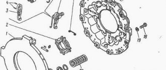
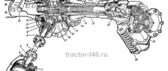
Design
The clutch housing is divided into two compartments by a partition in the middle:
- The front one, which houses the clutch and its release mechanism, and
- Rear, communicating with the gearbox and rear axle housing.
The rear compartment contains the coupling and PTO drive. The leading part of the clutch, consisting of pressure plates and a support disk , is installed on the three driving fingers of the diesel flywheel and constantly rotates with the flywheel.
The support disk is also attached to the flywheel with six bolts. The driven part of the clutch, consisting of the main clutch disk and the PTO drive clutch disk, is installed on the shaft splines.
The shaft is connected to the gearbox, and the shaft is connected to the PTO drive. The PTO drive clutch shaft is hollow, manufactured as one piece with the drive gear of the PTO gearbox . The main coupling shaft is located inside the shaft on two needle bearings.
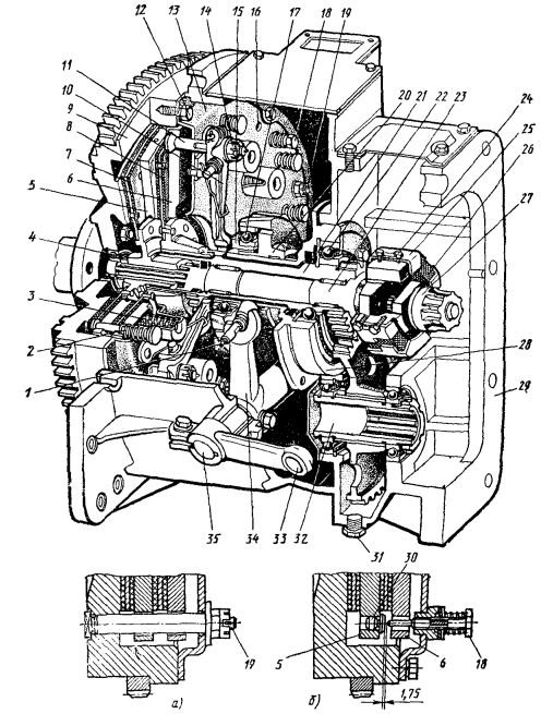
a - cut along the flywheel pin; b - section along the thrust bolt; 1 — oiler; 2 - spring; 3 - pressure spring. 4 and 22 - bearings; 5 and 6 — pressure plates; 7 — main clutch disk; 8 — PTO drive clutch disk; 9 — diesel flywheel; 10 — release lever; 11 - thrust; 12 and 24 - bolts; 13 — support disk; 14 - nut; 15 — thrust bushing; 16 — technological holes; 17 — release bearing; 18 - thrust bolt; 19 — leading finger; 20 - layering; 21 and 32 — PTO drive shafts; 23 — main coupling shaft; 25 — clamp; 26 — rubber element; 27 — gearbox input shaft; 28 — layering bracket; 29 — clutch housing; 30 — emphasis; 31 - plug; 33 — shutdown lever; 34 - fork; 35 - roller.
Read also: Is it possible to issue a deed of gift for a car?
At the front, the shafts rest on a bearing installed in the flywheel bore, and at the rear - on a bearing mounted on a tapping bracket fixed in the partition of the clutch housing.
The bearing is lubricated with grease placed into it during assembly. Due to the short duration of operation (only when the Yumz clutch is turned off), additional lubrication is not required during maintenance.
The bearing and needle bearings are lubricated by transmission oil supplied to the rear compartment of the clutch housing from the gearbox housing and rear axle. To prevent oil from getting into the front compartment from the rear compartment, the shafts are sealed with cuffs.
The driven disks are constantly pressed against the pressure disks and flywheel by pressure springs located between the support and pressure disks. In addition, the driven disk of the PTO drive clutch is clamped between the pressure disks by nine springs. One end of the spring rests against the disk, and the other against the head of a pin fixed in the disk and free in the hole of the disk.
When the Yumz-6 clutch is engaged, under the force of the pressure springs, the driven disks are pressed against the surfaces of the flywheel and pressure disks, and friction forces transmit torque to the input shaft of the gearbox, as well as to the PTO drive shaft.
The clutch is released using a release bearing, moving along the bracket and connected to the clutch pedal through a fork mounted on the release roller, a lever and a rod.
The release bearing is lubricated through a grease nipple on the release body. At the same time, the surface of the bracket along which the layer moves is also lubricated.
To access the oiler on the clutch housing, there is a hole on the left side that is closed with a plug. When you press the clutch pedal Yumz-6, the lift, moving along the bracket through the release bearing and thrust bushing presses on the double-arm release levers , swinging on axles installed in brackets on the support disk.
The release levers act through the crackers and nuts on the rods that are pivotally mounted in the pressure plate. Under the force applied to the pedal, the springs are compressed and the pressure plate moves.
Since the disk is connected to the disk through springs and pins, this disk well , moves with it .
The driven disk of the main clutch is released, and the transmission of torque from the diesel crankshaft to the transmission stops . The main clutch disengages. The transmission of torque to the PTO drive continues, since the driven disk of the PTO drive clutch remains pressed between the pressure plates by the force of the springs.
With further movement of the clutch pedal, the pressure plate of the main clutch rests on the bolts wrapped in the support disk and stops, and the PTO drive clutch disk, continuing to move, releases the driven disk, and the PTO drive clutch also disengages . The position of the thrust bolts is adjustable.
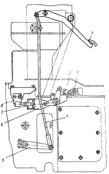
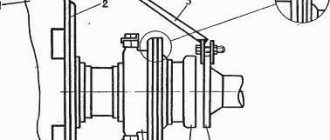
1 — pedal; 2 and 4 - thrust; 3 — locking roller; 5 — lever; 6 - amplifier; 7—thrust screw. 9 — bracket.
The gap between the thrust bolts and the stops on the disk should ensure that the main clutch is completely disengaged.
If this gap is too small, the main clutch will not disengage completely . If the gap is large, disengagement of the PTO drive clutch will be incomplete, since there will not be enough travel of the clutch pedal and disc to disengage this clutch. The optimal clearance is 1.75 mm, which corresponds to 1 1/6 turns of the stop bolt or seven clicks of the locking device installed on the bolt.
During operation, this gap increases due to wear of the discs. Therefore, during maintenance it must be restored.
The locking device that keeps the bolt from self-rotating is a spring-loaded washer, which with its antennae fits into the grooves on the bolt, and with its protrusions into the recesses of the socket on the support disk. When the bolt is rotated with a wrench, the protrusions of the washer, rotating with the bolt , move from one recess of the socket to another and emit a characteristic sound - a click.
There are three technological holes in the support disk, and three threaded holes in the pressure disk opposite them.
to screw the technological bolts into these holes . To do this, you can use three bolts securing the support disk to the flywheel. This is necessary so that when removing the clutch from the flywheel and installing it on it, the springs remain in a compressed state , which makes the work easier.
After the clutch is installed and secured to the flywheel, the service bolts must be removed.
For the correct interaction of the parts of the shutdown mechanism and to ensure the possibility of restoring the adjustment parameters of its drive during operation, the position of the release levers must be adjusted .
The position of the levers is adjusted by rotating the nuts after installing the clutch on the flywheel.
The cams of the release levers must be installed in the same plane at a distance of 73 mm from the plane of the hub flange of the driven disk of the PTO drive clutch.
During operation, the friction linings of the driven discs of the clutch wear out. As a result, the cams of the release levers approach the thrust sleeve of the release bearing, which can lead to incomplete engagement and slipping of the clutch.
To prevent this from happening, there must be a gap of 3-4 mm , which must be restored during maintenance of the clutch.
The clutch release mechanism is activated by a pedal through a rod and a lever mounted on the release shaft.
In the initial position, the pedal is held by the amplifier springs. When the clutch is disengaged, the amplifier's stop point passes through neutral, and the springs begin to act in the opposite direction , helping disengage the clutch and reducing pedal effort.
When the clutch is engaged, the pedal returns to its original position at the initial moment under the action of the clutch springs, and then, when the amplifier passes through neutral, under the action of the amplifier springs.
The pre-compression of the amplifier springs is regulated by a stop screw , and the moment when the amplifier passes through neutral is adjusted by changing the position of the bracket .
The gap between the cams of the release levers and the thrust sleeve of the release bearing is adjusted by changing the length of the rod. Indirectly, this gap is checked by the free play of the clutch pedal of the Yumz tractor, which should be within 30±5 mm .
The clutch engagement drive is interlocked with the gear shift mechanism, which allows you to change gears only when the main clutch is disengaged.
The gearbox locking roller, which is connected to the clutch release drive rod through a rod and lever, is also used to limit the pedal travel to disengage the main clutch.
The moment of complete disengagement of the main clutch, at which the PTO drive clutch is not yet disengaged, is fixed by a special clamp , against which the locking roller rests, turning when the clutch pedal is pressed.
The latch is connected to the lever by a rod. When you press the clutch pedal all the way to the lock, only the main clutch disengages.
If you first release the locking roller by moving the lock with a lever, and then press the clutch pedal all the way, the PTO drive clutch is and the main clutch is also disengaged.
The travel of the pedal until it stops in the latch, which ensures complete disengagement of the main clutch yumz, is regulated by changing the length of the locking rod .
Video, YuMZ clutch adjustment
Clutch adjustments
In the clutch of tractors YuMZ-6L, YuMZ-6M
make the following adjustments;
Free play of the pedal (the gap between the thrust bushing and the release levers);
The pedal travels all the way to the latch, ensuring complete disengagement of the main clutch;
The gap between the thrust bolts and the front pressure plate, which ensures disengagement of the main PTO drive without disengaging the clutch.
The clutches are adjusted in the following sequence.
Set the free play of the clutch pedal within 30+5 mm by changing the rod length. To increase free play, the rod should be lengthened, and to decrease it, it should be shortened.
Check the pedal travel all the way to the latch, which should be 145 ± 5 mm. If necessary, the pedal stroke is adjusted by the locking roller drive rod; to increase the pedal stroke, the rod is shortened, and to decrease it, the rod is lengthened.
The servo amplifier mechanism is adjusted so as to ensure minimal force on the pedal when the clutch is disengaged and a clear return of the pedal to its original position. Adjustment is made by moving the servo amplifier bracket along the oval holes. The servo amplifier springs are pressed with a thrust screw, for which it is unscrewed by 3 - 8 mm.
Remove the cover of the lower hatch in the clutch housing and tighten the bolts 24 until they stop (see Fig. 1), and then unscrew each of them 716 turns (seven clicks of the locking device).
In case of severe wear of the driven clutch discs, its adjustment is carried out by changing the position of the release levers while simultaneously changing the length of the main rod. The adjustment is performed in the following sequence:
Remove the cover of the lower clutch hatch;
Adjust the release levers using nuts to ensure a size of 73.5 mm between the end of the PTO driven disk hub and the cams of the release levers;
Change the length of the main rod and set a gap of 3 - 4 mm between the thrust bushing and the release levers. The difference in clearances for the three levers should not exceed 0.3 mm. After the clearance is finally established, the nuts of the release levers are pinned;
Screw in bolts 24 until they stop, and then release each of them 7/6 of a turn.
When a new or repaired (with replacement of discs) clutch operates, the discs intensively wear in and the initial adjustment is disrupted. During the running-in period (approximately 30 hours of tractor operation), the gap between the lift sleeve and the release levers is allowed to be 3+1 mm, and the difference in gaps for the three release levers should not exceed 1.3 mm.
Clutches of tractors YuMZ-6KL, YuMZ-6KM and YuMZ-8070... YuMZ-8280
They differ from each other only in the design and location of the control mechanism. Adjust the clutch after running in the tractor and every 500 operating hours. In the clutch, adjust the gap between the safety ring 6 (see Fig. 2) of the release levers 4 and the thrust sleeve 7 of the release bearing, as well as the gap between the thrust bolts 8 and the stops 9 on the pressure plate 3 of the main clutch.
Tractors YuMZ-6KL, YuMZ-6KM.
Adjustment sequence.
1. Remove the cover of the lower hatch in the clutch housing.
2. Screw in the thrust bolts 8 until they come into contact with the stops 9, and then unscrew each of them seven clicks of the locking device, which corresponds to a gap of 1.75 mm between the thrust bolts and stops 9,
3. Disconnect the rod 6 (see Fig. 3, a) of the clutch control mechanism drive from the release lever 7.
4. Turn lever 7 upward until the release bearing stops against the release lever safety ring, and then release it by 4.5 mm, which corresponds to a gap of 3 - 4 mm between the safety ring and the release bearing thrust bushing.
5. Adjust, without changing the position of lever 7, the length of rod 6 until the holes in the rod coincide with the hole in the lever and connect them.
After significant wear of the clutch discs, restoring the gap between the safety ring of the release levers and the thrust sleeve of the release bearing by changing the length of rod 6 may not be possible. In this case, you need to change the position of the release levers, and then shorten rod 6 and adjust the gap in the indicated order (see paragraphs 4 and 5).
To change the position of the release levers, do the following:
1. Remove the cover of the lower hatch in the clutch housing and unpin the nuts 5 (see Fig. 2) of the release lever rods.
2. Adjust the position of the release levers 4 by rotating the nuts 5 so that the safety ring is at a distance of 83 ± 0.5 mm from the plane of the hub flange of the driven disk 2 of the PTO. After adjustment, the safety ring must be in a plane perpendicular to the axis of rotation, i.e. in a plane parallel to the thrust sleeve 7 of the release bearing. The non-parallelism should not exceed 0.3 mm. Before the final check of parallelism, nuts 5 must be secured with cotter pins.
After replacing the discs or other repairs to the clutch, the position of the release levers 4 must also be adjusted with nuts 5 so that the distance between the plane of the hub flange of the PTO driven disk 2 and the plane of the safety ring 6 is equal to 83 ± 0.05 mm
Adjusting the clutch control mechanism.
In case of repair or replacement of parts of the clutch control mechanism, it must be adjusted in this sequence.
1. Disconnect rod 6 (see Fig. 3, a) from lever 7 and release the pedal by unscrewing nuts 1.
2. Make sure that bracket 9, through bolt 8, rests against the wall of the clutch housing. If necessary, adjust the bolt position.
3. Move lever 5 to stop 4 by rotating screw 10.
4. Adjust the gap between the thrust sleeve of the release bearing and the safety ring of the clutch release levers and connect rod 6 to lever 7.
5. Adjust the gear locking mechanism by changing the length of rod 2.
6. Start the engine and check the operation of the drive. Please note that after starting the engine, lever 5 must remain on stop 4. If, after starting the engine, the lever moves away from the stop, you need to loosen the tightening of nuts 1. The pedal must remain pressed against stop A.
Adjusting the safety valve of the hydraulic booster of the clutch control mechanism. In case of disassembly and reassembly or signs of malfunction of the safety valve appear, it is necessary to check the pressure and adjust the valve in this sequence.
1. Disconnect (with the engine stopped) oil drain line 13 from the hydraulic booster and install a pressure gauge in its place.
2. Plug the disconnected oil line, as oil will leak out of it while checking the valve.
3. Start the engine, set the maximum crankshaft speed and take the pressure gauge readings.
4. If necessary, adjust the valve to a pressure of 3 ± 0.5 MPa, while the oil temperature should be 50 ± 5°C.