Design and principle of operation of the chainsaw clutch mechanism
Most sawmills do not understand how the chainsaw clutch operates. It is not necessary to know the operating principle at work, but in case of malfunctions, you will need to know the design and features of the chainsaw clutch.
Modern chainsaws are equipped with centrifugal clutch mechanisms. Centrifugal clutch. This means that its performance depends on the torque of the engine. The main purpose of the clutch on a chainsaw is to ensure the transmission of torque from the engine crankshaft to the headset (chain) of the saw. The device operates automatically, and we will find out in detail how this happens.
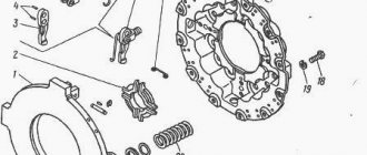
The clutch mechanism consists of the following structural elements:
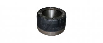
- A drum with a removable or non-removable sprocket is a gear train
- Friction pads. Under the influence of centrifugal force they move, engaging with the drum
- Spring. Provides crankshaft pressure
Now about the principle of operation of the clutch chainsaw.
When the tool's two-stroke engine starts, the crankshaft begins to rotate. The clutch is attached to a shaft to which the chain is connected by a sprocket. When the chainsaw is idling (shaft speed up to 2700 rpm), that is, the accelerator trigger does not stretch, the spring presses the friction pads, so that torque is not transmitted to the drum.
As soon as the saw selects a tool and begins to increase speed (maximum 14,000 rpm), the chain begins to move on the bar. This is due to the fact that the crankshaft rotation speed increases. Due to inertia, the friction pads (also called counterweights) move and engage the inner walls of the drum. As a result, the drum moves, which is connected by an asterisk. The rotating sprocket drives the chain.
The operating principle of the mechanism is simple due to its simple design. If this part fails, the chainsaw will not work properly. A detailed description of the operation of the chainsaw clutch mechanism is described in this material.
General information about clutches in tractors
The tractor clutch serves for smooth connection and short-term disconnection of the engine and power transmission. In addition, it protects power transmission parts from damage in the event of a sudden change in torque.
Tractors mainly use friction disc clutches, consisting of a driving and driven part and a control mechanism.
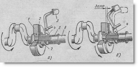
Diagram of the simplest clutch:
a - clutch is on; b - clutch is turned off; 1 - flywheel; 2 — driven disk; 3 — pedal 4 — fork; 5 - spring; 6 - driven shaft; 7 — driven disk hub
In the simplest coupling (Fig.), the leading part is the flywheel U, and the driven part is disk 2, the hub 7 of which is loosely placed on the shaft splines. The control mechanism consists of a spring 5, which presses the disk against the flywheel, and a pedal 3 with a fork 4.
When the clutch is engaged (see Fig. a), the disc is pressed against the flywheel. Due to the friction that arises between them, the disk and flywheel rotate as one unit and thus transmit torque from the crankshaft to the driven shaft 6.
When the pedal is pressed, fork 4, overcoming the resistance of spring 5, moves hub 7 along with the disk away from the flywheel (see Fig. b). In this case, the transmission of torque to the shaft stops and the clutch disengages.
At the beginning of switching on, while the disk is pressed only lightly against the flywheel, it slips. This ensures a smooth connection between the engine crankshaft and the power transmission mechanisms. When operating under normal load, the disc should not slip, as this will lead to severe overheating of the clutch, wear of the disc surfaces and even failure of the clutch. However, in the event of a sharp increase in load, when the resistance on shaft 6 exceeds the normal engine torque by 2-3 times, the disk briefly slips and thereby prevents damage to power transmission parts.
In order for the clutch to transmit more torque, it is necessary to increase the friction force. To do this, use both sides of the driven disk.
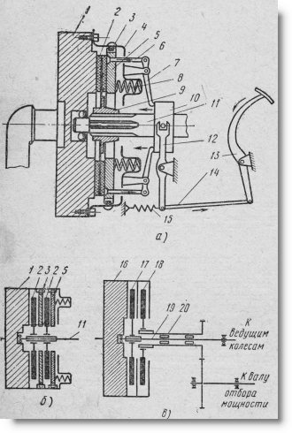
Schemes of permanently closed clutches:
a - single-disk; b - double-disc single; c - double (two-flow); 1 — flywheel, 2 — driven disk; 3 — leading pin, 4 — casing (support disk); 5 — pressure disk; 6 and 14 - thrust; 7 — lever; 8 - spring; 9 — driven disk hub; 10 - layering; 11 — driven shaft; 12— fork; 13 - pedal; 15 — return spring; 16 — flywheel 17 and 18 — driven disks that transmit rotation to the gearbox and BOM; 19 — driven shaft, transmitting rotation to the gearbox; 20 - tubular driven shaft of the BOM drive
The leading part is supplemented with pressure disk 5 (Fig. a), which rotates together with the flywheel, but has the ability to move in the longitudinal direction. Springs 8, resting with one end against the casing 4 attached to the flywheel, and with the other against the pressure disk, press it together with the driven disk against the flywheel.
The control mechanism, in addition to the spring 8, has retraction levers 7 connected by rods 6 to the pressure plate, as well as a tap 10 connected to the pedal 13. When the pedal 13 is pressed, the tap moves to the left using the rod 14 and fork 12 and presses on the ends of the levers 7. The outer ends of these levers, moving to the right, overcome the resistance of the springs, move the pressure disk away from the driven one and release the latter. To speed up the stop of the driven part of the clutch, which continues to rotate by inertia, some clutches have a special brake.
The considered clutch is called a single-plate clutch. If it does not provide the transmission of the required torque, then double-disc (Fig. above b) and multi-disc clutches are used. The amount of torque transmitted by the clutch, in addition to the number of discs, is affected by their diameter, material and condition of the friction surfaces and the force compressing the discs.
Depending on the condition of the surfaces, couplings are divided into dry and oil.
To increase the friction forces of dry clutches, linings made of friction materials - raybest, freevanite, etc. - are riveted or glued to the thin driven (less often to the driving) disks. Overheating and oiling of these linings reduces the coefficient of friction.
Oil clutches have steel discs without linings. Such clutches wear less and engage more smoothly, but they can transmit less torque than dry clutches. Therefore, they are made multi-disk and used where relatively small torques are transmitted, for example, in transmission mechanisms of starting engines.
Some tractors use double clutches (Fig. c). They differ from double-disc single clutches in that their driven friction discs 17 and 18 transmit rotation not to one, but to two different shafts 19 and 20. In fact, a double clutch consists of two single-plate clutches structurally combined in a common unit. One of them transmits rotation to the gearbox, and the other to the power take-off shaft.
Thus, the double clutch transmits engine power in two independent flows, which is why it is also called double-flow.
Depending on the design of the control mechanism, a distinction is made between permanently closed and non-permanently closed clutches.
The permanently closed clutch disengages (the discs open) only when the driver presses the pedal and holds it in this position.
With non-permanently closed clutches, the discs are compressed by a lever or lever-spring mechanism, operated by the driver using a hand lever.
Scheme of a non-permanently closed clutch:
a - clutch is on; b - clutch is turned off; 1 - flywheel; 2 - drive disk; 3 - pressure cam; 4 - connecting finger; 5 - earring; b - layering; 7 and 9 — levers; 8—traction; 10— driven shaft; 11 — cross; 12 and 13 — driven disks; 14 — retraction spring
In Fig. shows the most typical diagram of a non-permanently closed clutch.
Drive disk 2, connected to the flywheel, is located between the driven disks. The support driven disk 13 is fixedly mounted on the shaft 10, and the pressure driven disk 12 can move in the longitudinal direction. In Fig. b shows the position of the parts when the clutch is turned off. To turn it on, the tap 6 together with the earrings 5 are moved to the left (see Fig. a) using lever 9. The earrings turn the cams 3, which with their protrusions rest against the pressure disk and clamp the drive disk between the driven ones.
The elasticity of the parts (mainly the earrings and cams) allows the lift to be moved even after the gap between the disks has been selected. The force compressing the discs will be greatest when the earrings are perpendicular to the shaft. However, this position of the control mechanism is unstable. The shock is enough for the tap to move back under the action of elastic forces and disengage the clutch. Therefore, for reliable fixation, the lift is moved to the left all the way to the crosspiece 11. In this case, the compression of the disks is slightly reduced.
To disengage the clutch, tap 6 is moved to the right. When it passes the “unstable” position, the retractor springs 14 will move the pressure plate following the cams, resulting in the drive disk being released. In order to then keep the clutch in the disengaged state, no force needs to be applied to lever 9.
Non-permanently closed clutches are installed on the T-38M, S-100, T-100M and DT-20 tractors. However, due to insufficient smoothness of activation and the need for frequent adjustments, they are not used on new tractor models.
When does a clutch need to be replaced?
The chainsaw clutch is removed and replaced if a mechanism malfunction is detected. These disadvantages include:
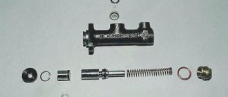
- Spring damage.
Depending on the model of the tool, the spring can be available in two types. Coil (tape or single) or steel sheet. The spring is damaged by tension, rupture or mechanical defect. To determine the cause of failure of the entire mechanism, you will need to remove the protective cover and drum - Drum damage and manufacturing.
The rupture of this part is often associated with fragments. If such a malfunction occurs, you will need to replace the drum. The inner part also wears out on the drum and needs to be replaced as well. If the drum is blue, it has overheated and should no longer be used. - Development of the mechanism.
This is primarily due to the spring extension, which can be replaced. The threaded connection also wears out. In the event of such a breakdown, the entire coupling will need to be replaced. - Star wear.
Depending on the type of sprocket (folding or non-folding), it is replaced by a drum and, if necessary, a clutch
READ How to Make a Motor for a Boat From a Gasoline Scutter
The service life of the clutch mechanism depends not only on the quality of the parts, but also on the correct operation of the tool. To extend the life of your chainsaw clutch, you need to pay attention to signs that reduce the resource. Such features include:
- Frequent chain jamming or biting in the forest. In such situations, the clutch takes on the entire load, protecting the engine from jamming.
- It is forbidden to increase the speed when using the handbrake, which also leads to wear of the mechanism due to overheating.
- The use of low-quality oil, the wrong choice of tires, chains, etc. All this also affects traction, increasing the load and, therefore, reducing service life.
Detecting a device malfunction is quite simple. To do this you need to cut the workpiece. If the chain speed decreases during cutting or stops when the load increases, then it is time to check the grip. We will discuss in detail how to remove and replace the clutch on a chainsaw in the next section.
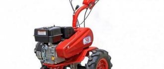
Motor-cultivator clutch and gearbox. Which ones are better?
I choose a motor cultivator. The process must be admittedly complex, but interesting. I haven’t worked with cultivators or walk-behind tractors before, so my technical knowledge is not very deep. In stores there are mainly MTD and Bolens (of the same type). You need to choose a model from T/240, T/245, T/330. I noticed that these models have different types of clutch and gearbox. Please tell me which clutch and gearbox works better, is more durable and more repairable?
oval wrote: which clutch and gearbox is better in operation, more durable and more repairable?
Like MB-1. stupid, strappy. I pulled the strap and it clicked. Relaxed - it disengaged. Simply unkillable. And repairability is easy to compare. Iron pulleys, durite strap.
Which gearbox is better, a worm or a chain?
IMHO - a chain. Dampens. and it’s repairable—it’s torn—he just riveted it together. Although I have never heard anything tearing. Most likely the engine will stall.
You're not worried about that. Few people have problems with clutches or transmissions. Mostly problems with engines, carburetors, ignitions.
You are correct: in principle, the gearbox should not float.
I actually have already repaired the gearbox twice, I have an MTZ-05. The first time in the workshop, the second on my own.
I did it better myself, pah, pah, pah.
But I'm not an indicator.
AlekseyAgafonov wrote: But I am not an indicator.
Of course, especially considering how old your device is
Please clarify what kind of reverse does the Caiman ECO 60 RC2 motor-cultivator have, belt or gear?
In my opinion, belts on a pulley are not serious. Better gearbox and oil-filled disc clutch. Tractor design. You can start moving smoothly, like driving a car. I have NMB-1. Belts tend to slip and wear out.
One frivolous company - Honda - makes frivolous walk-behind tractors weighing 90 kilograms on a frivolous belt drive
(description of 4 speeds, multiplier, wheel unlockers). This crap costs 2000 bucks without packaging. There are other small offices with this design, the majority of them. The gearbox is better with a gear or chain, the worm gets very hot when operating at full power, good smokers need a smoke break every half hour, low efficiency with a gear ratio of 1:25, if the oil overheats it can lift the bronze on the wheel
Yes, in our city, in company stores, there are Chinese Hondas with a belt drive for 2000 bucks. Nobody takes it. Neva for 24 thousand rubles. more practical. I just want to say, what’s the point of buying belts for the same money as a gearbox with a clutch. As a motorist, the box inspires more confidence in me.
I asked Honda dealers who takes their walk-behind tractors for 2000 bucks: the answer is - people who drive Lexus and live in a 3-story mansion
Why do they need a walk-behind tractor when they hire Tajiks? In my opinion this is not patriotic.
The caiman has a gear reverse
ovn83 wrote: and an oil-filled disc clutch. Tractor design.
Name at least one tractor with such a clutch.
Mini tractor BELARUS 082BS
Clutch, clutch, mechanism of transport vehicles for transmitting torque from an internal combustion engine to a gearbox. The clutch ensures short-term separation of the engine shaft and transmission shaft, shockless gear shifting and smooth starting of the vehicle. Depending on the number of driven discs, single-, double- and multi-disc clutches are distinguished. Clutches installed in cars are usually a single- or double-disc clutch, the discs of which are compressed by springs. To ensure smooth engagement of the clutch and reduce torsional vibrations of the transmission, flat springs are often installed between the friction linings of the discs, and the discs are attached to their hubs through an elastic coupling with coiled springs, etc. The clutch is released by a pedal through a lever or hydraulic transmission, and in heavy vehicles machines using a servo drive. Switching off can be automatic when changing gears. Multi-plate oil clutches (in motorcycles), normally open (in tractors), hydrodynamic or hydrodynamic in combination with friction (in cars), and sometimes electromagnetic clutches with a ferromagnetic mixture (usually in cars for the disabled) are also used as clutches.
Video: Replacing the Clutch of a Petrol Mower
First you need to prepare the necessary tools:
- The special key is called a stripper. This often comes with a chainsaw.
- Screwdriver for unscrewing the screws securing the protective cover
- Wrench. Used to unscrew the cap and secure the tire (supplied with the tool)
- Rope. Shut off the crankshaft. It is better to use asbestos, but any will do. A rope is used if the tool does not have a special piston locking key.
If disassembly is performed for replacement, then you need to prepare a new mechanism in advance. When purchasing a new coupling, you only need to know the exact brand of chainsaw, since the devices differ in outer diameter, thread and design of the working mechanism. The instructions for removing the clutch on a chainsaw are as follows:
- First you need to unscrew the nuts securing the casing and tires
- Remove the cover from the handbrake, chain and bar.
- Then proceed to remove the plastic cover to get to the spark plug. To do this, unscrew the screwdriver and remove the cover along with the air filter.
- The chainsaw spark plug is unscrewed with a spark plug key
- Insert the cable into the spark plug hole in the cylinder (install a special key, if available). This is done in order to dampen the crankshaft. If the diameter of the rope is several times smaller than the size of the hole for the candle, knots can be made on it
- Next, move on to the clutch screwdriver. To do this, take a special key that must be turned on. If you don't have a wrench, you can use a tool from an angle grinder or make your own puller, which is also not difficult
- The key veneers must be installed in the coupling holes and then continue to rotate the part. You need to rotate clockwise. Manufacturers usually indicate unscrewing instructions in the form of an arrow.
- As the clutch rotates, the piston reaches top dead center and the crankshaft locks. Then, applying a little force, the clutch will come off with further unscrewing of the mechanism
- The twisted coupling is removed from the chainsaw. If necessary, the drum with the sprocket is also removed.
READ Replacement Chainsaw Sprocket Husqvarna
The procedure is not complicated and does not take much time. Assembly is carried out in the reverse order of removal. To avoid any malfunctions, it is recommended to install exactly the same clutch on the corresponding tool model.
Friction clutch - clutch
After engaging the friction clutch, joint acceleration of the driving and driven systems begins until normal flashes appear in the diesel cylinders, capable of starting the engine. After starting the engine, the MCX automatically disconnects the leading (from the starting motor to the MCX) and the driven (from the MCX to the working body) systems.
When the friction clutch operates in an oil bath, oil is constantly supplied under pressure to the rubbing surfaces.
Tractors use friction clutches, which use friction forces to transmit torque. Each clutch consists of a driving and driven part, a pressure device and a control mechanism. The driving part of the clutch is connected to the engine crankshaft and rotates with it, and the driven part is connected to the power transmission shaft. The control mechanism acts on the pressure device, which brings together and with a certain force presses the driven part of the coupling to the driving part. The resulting frictional forces transmit torque. When the torque increases sharply when the engine is overloaded, the driving and driven parts of the clutch slip relative to each other, thereby eliminating the transmission of increased torque and preventing possible breakdowns of transmission parts.
Tractors mainly use friction clutches.
Although the principle of operation of friction clutches remains the same, their design is very diverse. Clutches are classified according to a number of characteristics.
In non-planetary gearboxes, friction clutches have rotating hydraulic boosters that engage the clutch.
| Transmission mechanism. |
The transmission mechanism consists of a friction clutch, a freewheel and a release mechanism.
| Mixing drum diagram. |
The transmission includes: single-disc friction clutch; a gearbox that provides three rotation speeds in one direction and three in the opposite direction; helical-bevel gearbox installed at an angle of 18 to the horizontal; cardan shafts and chain drive. A V-belt pulley is mounted on the main shaft of the gearbox to drive a centrifugal water pump.
Wear of the driven and driving elements of the friction clutch occurs during the off-on period and possible slipping of the clutch in the fully engaged state. Due to the difference in mechanical properties, the wear rates of the driving elements (usually metal) and driven elements (combined with friction plastic or composite linings) differ significantly (by several orders of magnitude). This is explained by the fact that micro-roughness of the surface of the metal driving element of the clutch causes plastic deformations when sliding in the surface layers of the lining, and elastic deformations arise in them. According to the theory of fatigue wear, the intensity of wear significantly depends on the stress state in the zones of actual contact with the roughness of interacting bodies and during plastic deformations is several orders of magnitude higher than during elastic deformations.
| Kinematic diagram of the OMS cleaning machine. |
The working body is driven into rotation through a friction clutch, which allows the working body to be turned off at the moment of passing through the couplings and linings. It rotates under overloads in the event that the cutters meet an obstacle (seam), to some extent softening the blows, as a result of which the cutters and gear are protected from damage.
Disc brakes are used in presses with friction clutches. In these brakes, the pressing force on the discs is carried out by springs.
In all drives, the pump is started by the friction clutch of the drive motor.
Removing the clutch on Stihl and Dolmar chainsaws
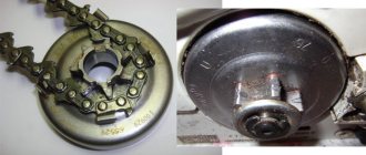
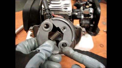
Of course, you noticed that chainsaws can have different designs of transmission devices. Up. Instructions for removing the clutch on the drum on which the sprocket is located inside. This device is available on most chainsaws, but not on Stihl tools. Chainsaws from a well-known manufacturer are equipped with a drum on which the star is located on the outside. It looks like the photo below.
A different sprocket location does not mean that the tool has a different clutch mechanism. However, this suggests that the principle of removing the clutch is different from the instructions given above. Therefore, we will learn how to remove the clutch on chainsaws from Stihl, Dolmar and others, on which the star is located outside.
- You must also remove the cover and wheel first to allow access to the clutch
- Unscrew the spark plug and secure the piston using a special wrench or cord.
- Then proceed to remove the sprocket and drum. To do this, use a screwdriver to break the ring and tighten it
- The drum with the bearing has been dismantled
- Using a “19” wrench (included in the tool kit), unscrew the nut with the left-hand thread connected to the mechanism. Unscrew clockwise
- After this, the appropriate repair or replacement of the part can be carried out.
Installation of a new or repaired part is carried out in the reverse order of removal. The procedure is almost the same as the first option, except for some functions. If you only need to replace the drum or sprocket, you won't need to remove the clutch, unlike the internal sprocket version.
READ How to Properly Thread Line into a Lawn Mower
Clutch repair. Spring replacement
Do not rush to change the entire mechanism, as a clutch malfunction can be eliminated by replacing the faulty part. The most common cause of malfunction. This is a spring that stretches and can be damaged. The already extended spring is faulty. If the spring is damaged, it can be replaced to restore the tool. Replacement instructions depend on the design of the mechanism, since compressor devices come in different types, but all of them must be replaced. This procedure is not so complicated, as it requires special attention and sequence of actions. How to replace the spring on a chainsaw clutch is shown in detail in the video.
If the friction lining is damaged, this part can also be replaced. Replacing the part is also necessary if the threaded connection wears out, which occurs when the coupling is frequently removed and replaced. To understand the cause of a part malfunction, you must first conduct a visual inspection. If the sprocket teeth are worn, they should be replaced. The fixed stars must be replaced by a drum.