KamAZ-5320, PGU: design and principle of operation
What is the KamAZ-5320 PGU device? This question interests many beginners. This abbreviation may confuse an ignorant person. In fact, the PGU is a pneumatic hydraulic power steering. Let's look at the features of this device, its operating principle and types of maintenance, including repairs.
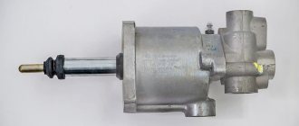
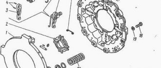
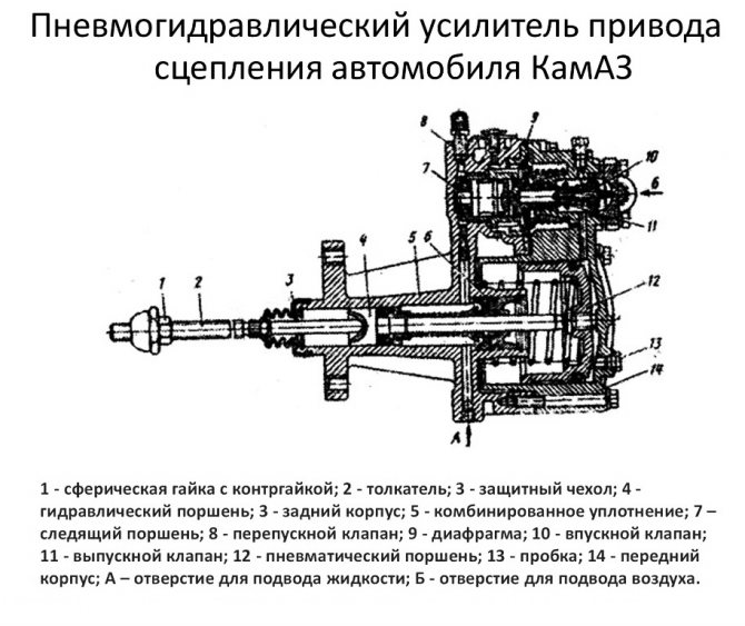
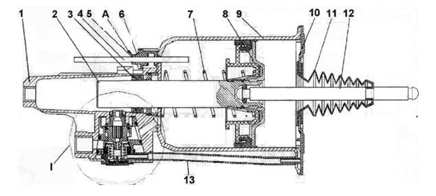
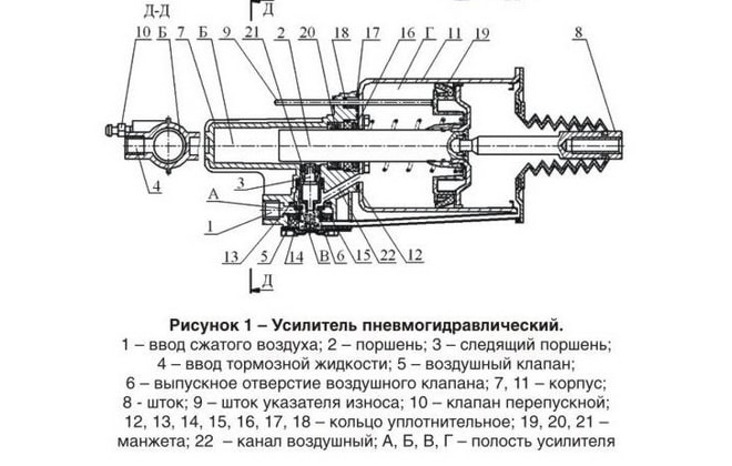
- 1 – spherical nut with lock nut.
- 2 – piston pusher of the clutch deactivator.
- 3 – protective cover.
- 4 – clutch release piston.
- 5 – back part of the frame.
- 6 – complex seal.
- 7 – follower piston.
- 8 – bypass valve with cap.
- 9 – diaphragm.
- 10 – inlet valve.
- 11 – graduation analogue.
- 12 – pneumatic type piston.
- 13 – drain plug (for condensate).
- 14 – front part of the body.
- “A” – supply of working fluid.
- “B” – supply of compressed air.
Pumping PSU on KamAZ
It is advisable to do this work together. If a person is experienced, he can do everything alone. Bleeding the KamAZ clutch begins with thoroughly cleaning the rubber cap of the bypass valve from dust, dirt and grease. After this, a standard rubber hose is put on it. The second end of this hose is lowered into a suitable container that already contains the working fluid. The container should be filled no more than a third with it.
Next, you need to sharply and quickly press the clutch pedal three or four times. The last time it is not released, but held in the pressed position. In this case, it is necessary to unscrew the bypass valve slightly. At this moment, the liquid inside the pneumatic amplifier under pressure will begin to flow into the glass container. It is important that characteristic air bubbles indicate that there is air in the system.
You need to pump the PSU on a modern KamAZ 65115 several times until there are no more bubbles. After this, the bypass valve is screwed on, the hose is disconnected, and the rubber cap is put on. Be sure to add working fluid to the tank - its level in it should not be lower than 4 cm from the top edge.
You can bleed the clutch on a KamAZ truck without a glass container. In this case, its role is played by a conventional pump - liquid is poured into it.
With the right approach and step-by-step work, pumping the pneumatic power steering on a KamAZ truck will not take much time and will be completed successfully.
When replacing the PSU or clutch master cylinder, you have to refill the system with brake fluid, so it becomes necessary to remove air plugs from the pipes and cylinders. The usual method of pumping by pressing the pedal and releasing air through the bypass valve, as a rule, does not give any results. Therefore, we have to use alternative pumping options.
The simplest and most effective way is to fill the brake fluid through the PSU bypass valve. To do this, you need to use a regular pump for inflating car tires. Pour liquid into it. Connect the hose to the PSU bypass valve and fill the fluid until it appears in the expansion tank of the clutch master cylinder. After this, close the bypass valve and press the clutch pedal several times. All clutches are bled. And you don't need to put in any more effort.
If you have already filled the fluid through the expansion tank and you cannot bleed the clutch, you can cheat the situation in another way. I can’t say one hundred percent why this happens, but if you press the pedal a little and fix the clutch master cylinder piston with a stiff wire so that the piston cannot return to its original position,
When you press the pedal again, the clutch begins to pump. If you perform this operation several times, the clutch will be completely pumped. This method almost always helps. Apparently, air is squeezed out of the cylinder cavity and it begins to work, which leads to the desired result.
Read more: How to remove vag connectors
There is another option for pumping when nothing else helps. Forcefully squeeze out the clutch fork drive lever, that is, using a crowbar or a powerful pry bar, squeeze out the clutch basket. In this case, the PSU rod that presses on the lever will be released. In this case, just a few presses on the clutch pedal will allow the rod to rest against the lever again, after which the clutch will begin to pump.
I would also like to draw your attention to one detail. There is a rubber seal on the rod of the main working cylinder; it very often breaks and jumps off the rod, but without it it is almost impossible to bleed the clutch, and therefore you have to constantly check its presence.
It is also worth paying attention to how the PGU is installed; if on KamAZ 5320 the installation does not raise any doubts, then on the 65115 PGU it can be installed and vice versa. And if in doubt, make sure the bypass valve is on top. Otherwise, the clutch will not bleed.
The abbreviation PGU stands for pneumatic hydraulic clutch booster. This is an important part of the car design. For KAMAZ vehicles it structurally consists of:
- round nut;
- a pusher that disengages the clutch;
- covers for protection from negative mechanical influences;
- piston;
- complex seal;
- valves;
- traffic jams;
- fuel supply;
- a system that compresses the air flow;
- spring mechanism;
- gearbox;
- diaphragmatic saddle.
The operating diagram of the pneumatic hydraulic booster looks like this:
- Pressing the clutch pedal.
- Exposure to fuel activates the rod and pistons.
- The intake valve moves until it opens.
- The air flow moves to the pneumatic piston.
- When the fork moves away, the clutch disengages.
Purpose and device
A truck is a fairly massive and large-sized vehicle. Controlling it requires remarkable physical strength and endurance. The KamAZ-5320 PGU device makes it easier to adjust the vehicle. This is a small but useful device. It makes it possible not only to simplify the driver’s work, but also increases work productivity.
The node in question consists of the following elements:
- Piston pusher and adjusting nut.
- Pneumatic and hydraulic piston.
- Spring mechanism, gearbox with cover and valve.
- Diaphragm seats, control screw.
- Bypass valve and piston follower.
Peculiarities
The amplifier housing system consists of two elements. The front part is made of aluminum, and the rear part is made of cast iron. A special gasket is provided between the parts, which acts as a seal and diaphragm. The follower mechanism automatically regulates the change in air pressure on the pneumatic piston. This device also includes a sealing collar, springs with diaphragms, as well as inlet and outlet valves.
Operating principle
When the clutch pedal is pressed under fluid pressure, the KamAZ-5320 PGU device presses on the rod and piston of the follower, after which the structure, together with the diaphragm, moves until the intake valve opens. The air mixture from the vehicle's pneumatic system is then supplied to the pneumatic piston. As a result, the forces of both elements are summed up, which allows you to retract the fork and disengage the clutch.
After the foot is removed from the clutch pedal, the pressure of the supply main fluid drops to zero. As a result, the load on the hydraulic pistons of the actuator and follower mechanism is reduced. For this reason, the hydraulic piston begins to move in the opposite direction, closing the inlet valve and blocking the flow of pressure from the receiver. The pressure spring, acting on the follower piston, moves it to its original position. The air initially reacting with the pneumatic piston is released into the atmosphere. The rod with both pistons returns to its initial position.
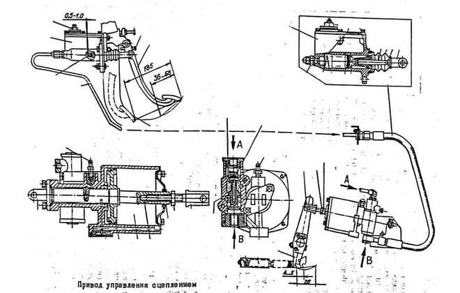
How to upgrade
Pumping of the CCGT unit at MAZ is carried out as follows:
- Make a homemade pressure device from a plastic bottle with a capacity of 0.5-1.0 liters. Holes are drilled in the lid and bottom, into which nipples from tubeless tires are then installed.
- It is necessary to remove the spool valve from the part mounted in the bottom of the container.
- Fill the bottle 60-70% with fresh brake fluid. When filling, close the hole in the valve.
- Connect the container with a hose to the fitting installed on the amplifier. A valve without a spool is used for connection. Before installing the line, you need to remove the protective element and loosen the fitting by turning 1-2 turns.
- Apply compressed air to the bottle through the valve installed in the cap. The gas source can be a compressor with a tire inflation gun. The pressure gauge installed on the unit allows you to control the pressure in the container, which should be within 3-4 kgf/cm².
- Under the influence of air pressure, liquid enters the cavities of the amplifier and displaces the air present inside.
- The procedure continues until the air bubbles in the expansion tank disappear.
- After filling the lines, it is necessary to tighten the fitting and bring the liquid level in the tank to the required value. A level located 10-15 mm below the edge of the filler neck is considered normal.
The reverse pumping method is allowed, when the liquid is supplied under pressure into the tank. Filling continues until gas bubbles stop coming out of the fitting (previously unscrewed by 1-2 turns). After filling, the valve is tightened and closed on top with a protective rubber element.
After bleeding the PSU clutch, it is recommended to check the condition of the rods, which should not be deformed. Additionally, the position of the brake lining wear sensor is checked, the rod of which should not protrude beyond the pneumatic cylinder body by more than 23 mm.
After this, you need to check the operation of the amplifier on a truck with the engine running. If there is pressure in the car's pneumatic system, it is necessary to press the pedal all the way down and check the ease of gear shifting. Gears should shift easily and without extraneous noise. When installing a box with a divider, you need to check the operation of the unit drive. In case of incorrect operation, the position of the control bracket must be adjusted.
CONSTRUCTION AND OPERATION OF WABCO CCGT
The clutch is released using a pneumohydraulic booster (PGU) from Wabco.
The PGU consists of 3 main parts: an actuator pneumatic cylinder, a servo system and a clutch lining wear indicator.
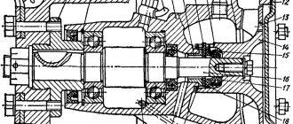
The CCGT structure is shown in Fig. 1.
Rice. 1. Pneumohydraulic booster (PGU) from Wabco:
1 — hydraulic housing; 2 — hydraulic piston; 3 — hydraulic cuff; 4 - wear indicator on the masonry; 5 — wear indicator washer; 6 — pointer body; 7.10—pressure spring; 8 — pneumatic piston; 9 — pneumatic cylinder; 11 — cover; 12 — rod; 13 — drainage tube. A - gap when the linings are worn; I - CCGT tracking system.
When you press the clutch pedal, the fluid pressure from the main cylinder is transmitted through pipelines to the pneumatic hydraulic booster, where it acts on the hydraulic piston 2 (Fig. 1) of the PSU and piston 1 (Fig. 2) of the follower device.
Under the action of the follower piston, pneumatic piston 2 moves (Fig. 2), which acts on the follower valve 5. The valve opens air access to the pneumatic cylinder 9 (Fig. 1) of the PSU, increasing the force effect of the PSU rod 12 on the clutch release fork. With the help of a tracking device, the air pressure entering the pneumatic cylinder of the PSU automatically changes, depending on the effort of the driver on the clutch pedal.
After the pedal stops working, the liquid pressure in the CCGT is released, the pneumatic valve of the tracking system is closed, and the pneumatic piston of the CCGT is set to its original state.
Using a pressure spring, piston 8 (Fig. 1) of the PSU with rod 12 is always connected without backlash to the clutch fork, clutch, diaphragm spring, and clutch pressure plate. When the clutch linings are worn, a backlash-free connection ensures that the piston of the PSU does not track the wear of the linings - as the piston wears, it moves more and more deeper into the PSU and affects the wear indicator of the linings.
The wear indicator 4 moves out more and more under the influence of the piston, the indicator washer 5 moves away from the indicator housing 6 and when the gap between the washer and the wear indicator reaches 23 mm, the wear of the linings reaches a critical value and it is necessary to replace them with a lining or a driven disk with linings assembled .
Read also: Massagers for car seats
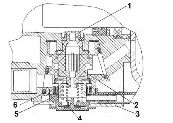
Rice. 2. CCGT tracking system:
1 — hydraulic piston; 2 — pneumatic piston; 3 - cover; 4 — breather; 5 - valve; b — tracking system housing.
The applied forces required for the truck's operating processes are proportional to the dimensions of the vehicle. KamAZ PGU reduces the load required for the functioning of the most important element in driving a vehicle, the clutch.
An uninitiated user is unlikely to appreciate the unit, because without an amplifier, the gear shift circuit and the operating condition of the car will not be affected. However, the direct participant in management knows the true price of the mechanism. With the absence of a PSU, driver fatigue increases and the maneuverability of the equipment decreases. As a result, road safety suffers and the number of accidents increases, which means human lives.

Production
The KamAZ-5320 PGU device is suitable for many model modifications of this manufacturer. Most old and new tractors, dump trucks, and military variants are equipped with pneumatic-hydraulic power steering. Modern modifications produced by various companies have the following designations:
- Spare parts for KamAZ (PGU) manufactured by KamAZ OJSC (catalog number 5320) with vertical placement of the tracking device. The device above the cylinder body is used on variations under the index 4310, 5320, 4318 and some others.
- WABCO. CCGT units under this brand are manufactured in the USA and are distinguished by their reliability and compact dimensions. This equipment is equipped with a system for monitoring the condition of the linings, the level of wear of which can be determined without dismantling the power unit. Most trucks with a 154 series transmission are equipped with this type of air-hydraulic equipment.
- Pneumatic hydraulic clutch booster "VABKO" for models with ZF type gearbox.
- Analogues produced at a plant in Ukraine (Volchansk) or Turkey (Yumak).
In terms of choosing an amplifier, experts recommend purchasing the same brand and model that was originally installed on the machine. This will ensure the most correct interaction between the amplifier and the clutch mechanism. Before changing the unit to a new variation, consult a specialist.
Service
To maintain the operating condition of the unit, carry out the following work:
- Visual inspection to detect visible air and fluid leaks.
- Tightening the fixing bolts.
- Adjust the free play of the pusher using a spherical nut.
- Adding working fluid to the system tank.
It is worth noting that when adjusting the KamAZ-5320 PGU of the Wabco modification, the wear of the clutch linings is easily visible on a special indicator extended under the influence of the piston.
Inspection and testing work
Initially, it is necessary to determine whether the clutch needs to be adjusted and bled. This can be determined by the presence or absence of air leakage. The stronger the leak, the worse the pneumatic hydraulic booster works.
You can check by simply pressing the pedal (the engine must be turned off). If the driver hears a characteristic whistle, this indicates a strong leak. If you cannot detect it by sound, you can apply a soap solution. The appearance of bubbles will indicate a malfunction of the clutch system.
Read more: How to set the time on an alarm
Before pumping the clutch on a KamAZ, the PSU device must be tightened with fastening bolts. It is also advisable to make sure that there is enough liquid in the tank to meet the needs of the system. Also check that the springs that control the movement of the corresponding clutch mechanisms are not stretched.
Disassembly
This procedure, if necessary, is performed in the following order:
- The back of the body is clamped in a vice.
- The bolts are unscrewed. Remove the washers and cover.
- The valve is removed from the body part.
- The front frame is dismantled along with the pneumatic piston and its membrane.
- The following are removed: the diaphragm, the follower piston, the retaining ring, the clutch release element and the seal housing.
- The bypass valve mechanism and the hatch with the outlet seal are removed.
- The frame is removed from the yews.
- The thrust ring of the rear part of the housing is dismantled.
- The valve stem is freed from all cones, washers and seats.
- The follower piston is removed (you must first remove the stopper and other related elements).
- The pneumatic piston, cuff and retaining ring are removed from the front part of the housing.
- Then all parts are washed in gasoline (kerosene), sprayed with compressed air and go through the defect detection stage.
Breakdown options
Any mechanism has its own resource, therefore, breakdowns are inevitable. Some car parts are replaced as planned after traveling a certain mileage. The clutch is a specific “organ” of the car that is constantly used. Moreover, the service life directly depends on the conscientious and careful attitude of the driver. If you squeeze the accelerator carelessly, throw it, or don’t press it all the way, you can quickly “burn the clutch” or damage the PSU. Technically, these problems can be reduced to several points.
- The rubber ring or cuff swells, and accordingly, the PSU follower piston jams. A jammed part, designed to be in constant motion, naturally stops in one position, therefore slowing down the operation of the entire system.
- A damaged intake valve produces too little compressed air. Air flows help the system create the necessary pressure, the absence of which leads to breakdown.
- Air inside the hydraulic drive disrupts circulation. The driver may feel an excessive amount of air in the form of sagging of the clutch pedal.
Due to the fact that the basis of the operation of the CCGT is musculoskeletal moments occurring under high pressure, subsidence of soft rings, cuffs, lack of air or its presence in the wrong places lead to breakdowns of the entire system, disrupting the operation of the CCGT.
Read more: How much gas does a Niva use?
PGU KamAZ-5320: malfunctions
Most often, the following problems occur in the node in question:
- The compressed air flow is supplied in insufficient quantities or completely absent. The cause of the malfunction is swelling of the inlet valve of the pneumatic booster.
- Jamming of the follower piston on the pneumatic booster. Most likely, the reason lies in the deformation of the o-ring or cuff.
- There is a “failure” of the pedal, which does not allow the clutch to be completely disengaged. This problem indicates that air has entered the hydraulic drive.
Malfunctions of KamAZ PGU
Inspection and testing of the performance of the GPU is carried out together with the clutch mechanism. The procedure for carrying out manipulations is described in the documentation for each car. The amplifier is checked for oil and air leaks, and the tightening forces of the fasteners are monitored. Adjust the stroke of the foot lever by positioning the spherical nut, and check the fluid level in the hydraulic tank. In case of serious breakdowns, the KamAZ PSU is replaced or repaired.
The replacement is accompanied by manipulations:
- Open the bypass valve to allow air masses to escape;
- Remove the spring mechanism pressing the clutch deactivation fork shaft lever;
- Remove lubricant from the hydraulic circuit;
- Disconnect the pneumatic and hydraulic pipes;
- Remove the PSU.
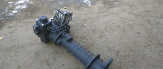
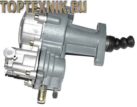
Dismantled KamAZ PSU:
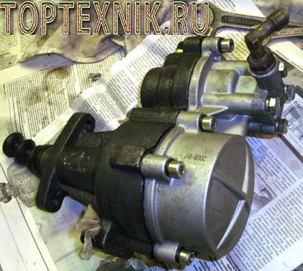
After dismantling, the technical condition of the CCGT parts and assemblies is checked. Attention is paid to the seals and the cylinder mirror - a surface without traces of mechanical impact. In addition, the internal diameter is measured to ensure compliance with established tolerances and fits.
A repaired or newly purchased amplifier is mounted in place by performing the steps in reverse order. After installation, check the tightness of the hydraulics and pneumatics. To do this, fill the circuit with liquid in the required volume.
As a rule, the amplifier works without problems for five to ten years. In case of breakdowns, it is more advisable to replace the product with a new one. CCGT units are repaired for minor or non-serious defects. The reasons for the failure of the KamAZ CCGT unit, possible malfunctions and their elimination are carried out on the equipment by service workers.
Frequently observed breakdowns:
- Under the influence of oil, the rubber seals swelled, and as a result, the PGU piston jammed;
- The exhaust valve does not allow air masses to pass through, or does not allow air masses to pass through in an insufficient volume;
- The presence of air bubbles in the hydraulic circuit, as a result, failures in the operation of the foot lever.
Replacement and installation
To replace the node in question, perform the following manipulations:
- The air is being bled from the KamAZ-5320 CCGT unit.
- The working fluid is drained or the drain is blocked using a plug.
- The clutch spring fork is removed.
- The water and air supply pipes are disconnected from the device.
- The fastening screws to the crankcase are unscrewed, after which the unit is dismantled.
After replacing deformed and unusable elements, the system is checked for leaks in the hydraulic and pneumatic parts. Assembly is carried out as follows:
- Align all the fixing holes with the sockets in the crankcase, after which the amplifier is secured using a pair of bolts with spring washers.
- The hydraulic hose and air line are connected.
- The release spring mechanism of the clutch release fork is mounted.
- Brake fluid is poured into the compensation reservoir, after which the hydraulic drive system is pumped.
- Re-check the tightness of the connections for leakage of working fluid.
- If necessary, adjust the size of the gap between the end part of the cover and the travel limiter of the gear divider activator.
Bleeding the clutch hydraulic system
After a detailed inspection and adjustment of all components of the clutch hydraulic system has been completed, it is necessary to perform the last action, which will help eliminate all problems in its operation, bleed it.
Instructions:
- Bleeding the hydraulic system should be carried out by 2 people.
- Remove dust and dirt from the rubber protective cap, remove it and put on the hose.
- One end of the rubber hose is attached to the valve, and the second must be lowered into a glass container with a capacity of approximately 0.5 liters.
- The container should be 1/3 full.
- When the hose is already in the container, you need to press the clutch pedal 3-4 times with a very sharp and strong movement and hold it.
- If there is air in the hydraulic system, then its presence is indicated by bubbles in the working fluid.
- When the liquid stops flowing from the hose, pumping can be completed. To carry out this work, you can also contact a special service center, a tire shop that services KamAZ trucks.
Repairing a viscous coupling Hyundai Tussan
How to remove tinting from a window
Where to buy mud flaps for Cherie Amulet
What is the fine for speeding?
Overview of program capabilities for car services and service stations autodealer.ru
Tweet
21.01.2019
0 Comments
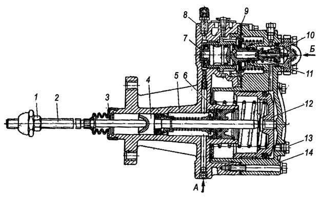
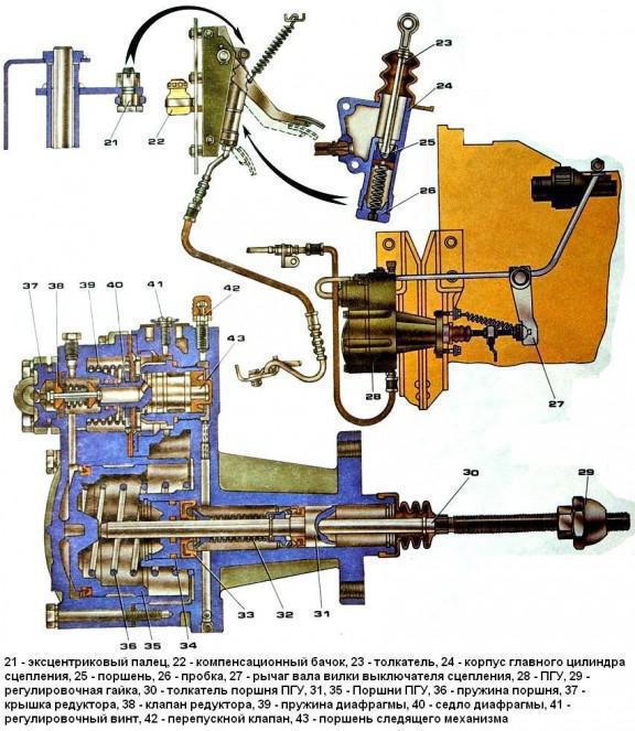
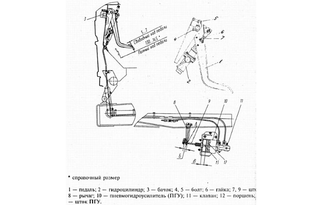
Schematic diagram of connection and placement of node elements
The operating principle of the KamAZ-5320 PGU is easier to understand by studying the diagram below with explanations.
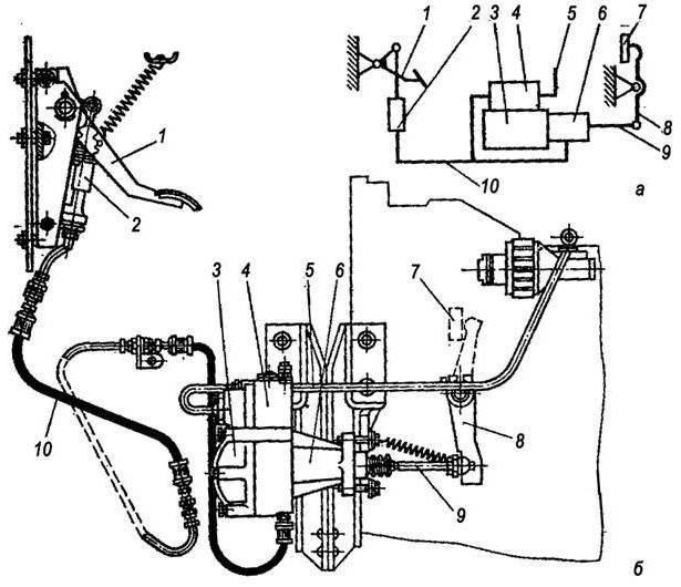
- a – standard diagram of interaction of drive parts.
- b – location and fixation of node elements.
- 1 – clutch pedal.
- 2 – main cylinder.
- 3 – cylindrical part of the pneumatic amplifier.
- 4 – follower mechanism of the pneumatic part.
- 5 – air duct.
- 6 – main hydraulic cylinder.
- 7 – release clutch with bearing.
- 8 – lever.
- 9 – rod.
- 10 – drive hoses and pipes.
The unit in question has a fairly clear and simple structure. Nevertheless, its role when driving a truck is very significant. The use of a PSU can significantly facilitate machine control and increase the efficiency of the vehicle.
source
Purpose and role of PSU in KAMAZ vehicles
In a number of old and all new models of KAMAZ trucks (military 4310, dump trucks 55111, 65115 and 6520, flatbed 43118 and 5320, tractors 5460 and 6460 and others), a pneumohydraulic booster (PGU) is integrated into the clutch drive system. This is due to the need to make the driver’s work easier, since the clutch in a truck has a large mass, and the springs develop a significant clamping force on the discs, and frequent disengagement leads to excessive fatigue.
The PSU greatly simplifies the task of disengaging the clutch, minimizing driver fatigue, while at the same time increasing safety (since in an emergency, disengaging the clutch will not require additional effort, and even at the end of the work shift the driver can easily do it) and improving the controllability of the truck.
It should be noted that in a number of KAMAZ models the PGU is simultaneously included in the control system of the gear divider (multiplier), which is installed between the clutch and the gearbox (most often it is an integral part of the gearbox). When changing gears, the divider must be turned off, which is ensured by the car's pneumatic system. The divider is switched off using a valve driven by the CCGT rod. Thus, when using a divider, it is turned off and on automatically simultaneously with the clutch being turned off and on when the pedal is pressed. Such a system is implemented on KAMAZ-5320 and many other models.
Design and principle of operation
Pneumohydraulic amplifiers (PGU) are produced in several modifications, differing in the location of the lines and the design of the working rod and protective cover.
The CCGT device includes the following parts:
- a hydraulic cylinder installed under the clutch pedal, together with a piston and a return spring;
- the pneumatic part, which includes a piston common to pneumatics and hydraulics, a rod and a return spring;
- a control mechanism equipped with a diaphragm with a release valve and a return spring;
- valve mechanism (for intake and exhaust) with a common rod and an elastic element to return the parts to the neutral position;
- lining wear indicator rod.
To eliminate gaps, the design has preload springs. There is no play in the connections to the clutch control fork, which allows you to monitor the degree of wear of the friction linings. As the thickness of the material decreases, the piston is recessed into the depth of the amplifier body. The piston acts on a special indicator that informs the driver about the remaining clutch life. Replacement of the driven disk or linings is required when the indicator rod reaches a length of 23 mm.
The clutch booster is equipped with a fitting for connection to the standard pneumatic system of the truck. Normal operation of the unit is possible at a pressure in the air lines of at least 8 kgf/cm². To attach the PGU to the truck frame, there are 4 holes for M8 studs.
Operating principle of the device:
- When you press the clutch pedal, force is transferred to the piston of the hydraulic cylinder. At the same time, a load is applied to the piston group of the follower rod.
- The follower automatically begins to change the position of the piston in the pneumatic power section. The piston acts on the control valve of the follower device, opening the air supply into the cavity of the pneumatic cylinder.
- Gas pressure provides force on the clutch control fork through a separate rod. The tracking circuit automatically adjusts the pressure depending on the force of pressing the clutch pedal with your foot.
- After releasing the pedal, the fluid pressure is released, and then the air supply valve closes. The piston of the pneumatic section returns to its original position.
General structure and principle of operation of the CCGT unit
Currently, several types of PSUs are used on KAMAZ vehicles, but they all have a fundamentally identical design and operating principle. The amplifier has two interconnected systems combined in a common housing:
- Tracking device;
- Executive pneumatic cylinder.
A tracking device is necessary to control the amplifier; it monitors the force the driver presses the clutch pedal and, at the right moments, supplies air under pressure to the slave cylinder. The follower device consists of a diaphragm (in some CCGT units it also acts as a gasket between the housing parts) and a piston, which are included in the hydraulic circuit of the clutch pedal, and two associated pneumatic valves (inlet and outlet), which form part of the pneumatic circuit. Therefore, a tube for supplying brake fluid and a tube for supplying compressed air from the car’s pneumatic system are connected to the amplifier.
The actuator pneumatic cylinder serves directly to drive the clutch. This unit consists of a housing that plays the role of a cylinder, in which a large diameter piston and a spring are installed. The piston is rigidly connected to a pusher, which comes out of the PSU housing through a system of seals - with its help the clutch is disengaged and engaged. In a number of models, a stop is also installed on the pusher, through which the gearbox divider switch-off valve is controlled.
The KAMAZ PGU is a compact unit that is usually mounted directly on the clutch housing. In this case, the amplifier pusher rests against a specially located lever of the clutch release fork shaft. Typically, the pusher does not have a rigid connection with the fork shaft lever, but rests against it through a spherical nut. This solution protects the PSU from damage and also allows adjustments to be made by changing the position of the nut on the pusher.
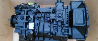
Design and principle of operation of KamAZ PGU with gearbox 154
On KamAZ 65115, KamAZ 65116, KamAZ 65117, KamAZ 6520, KamAZ 5460, KamAZ 6460 Euro 2, Euro 3 vehicles with a single-disc clutch and gearbox 154 (KPP-154), a WABCO PGU is installed.
The WABCO pneumohydraulic clutch booster consists of 3 main parts:
- Executive pneumatic cylinder;
- Tracking system;
- Lining wear indicator.
The figure shows:
- The body is hydraulic;
- Hydraulic piston;
- Cuff;
- Lining wear indicator;
- Lining wear indicator washer;
- Lining wear indicator housing;
- Pressure spring;
- Pneumatic piston;
- Pneumatic cylinder;
- Pressure spring;
- Case;
- Stock;
- Drainage tube;
A - gap when the linings are worn;
I - CCGT tracking system.
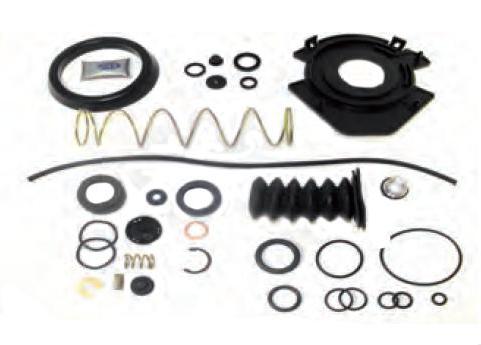
The lining wear indicator and its washer are shown in the photo below:
The WABCO CCGT has the following operating principle:
When you press the clutch pedal, the fluid pressure from the master cylinder is transmitted through pipelines to the pneumatic hydraulic booster, where it acts on the hydraulic piston (item 2 in the main picture) of the PSU and piston 1 of the follower device (see the picture of the follower device below).
- Hydraulic piston;
- Pneumatic piston;
- Lid;
- Breather;
- Valve;
- Tracking system housing.
Under the action of the follower piston, pneumatic piston 2 moves (in the follower figure), which acts on the follower valve 5. The valve opens air access to the pneumatic cylinder 9 (in the main figure) of the PSU, increasing the force effect of the PSU rod 12 on the clutch release fork. With the help of a tracking device, the air pressure entering the pneumatic cylinder of the PSU automatically changes, depending on the force of the driver on the clutch pedal.
after the pedal stops working, the liquid pressure in the CCGT is released, the pneumatic valve of the follow-up system is closed, and the pneumatic piston of the CCGT is set to its original state.
Using the bearing spring 8, the PGU with rod 12 is always connected without play to the clutch release fork, clutch, diaphragm spring of the clutch basket and clutch pressure plate. When the linings of the driven clutch disk wear, a backlash-free connection ensures that the PSU piston monitors wear - as the piston wears, it moves more and more deeper into the PSU and affects the lining wear indicator.
The wear indicator 4 moves out more and more under the action of the piston, the indicator washer 5 moves away from the indicator body 6 and when the gap between the washer and the body reaches 23 mm, the wear of the linings reaches a critical value and requires replacement of the driven disk.
Availability, prices and applicability of PGU on KamAZ vehicles, see here.
sht-ufa.ru
Types of PSU of KAMAZ vehicles
Currently, trucks of the Kama Automobile Plant use several types of CCGT units of domestic and foreign production. They differ in design and applicability.
The CCGT with catalog number 5320 is manufactured at KAMAZ OJSC and has a classic design with a vertical arrangement of the tracking device and the actuating pneumatic cylinder (the tracking device is located above the cylinder body). Used on cars models 5320, 4310, 43118, 55111 and others.
The WABCO PSU is manufactured in the USA, has compact dimensions, and is additionally equipped with a lining wear indicator (allows you to track the life of the amplifier without disassembling it). Used on new models KAMAZ-5460, 6450, 6460, 6520, 6522, 65115, 65116, 65117 and others with gearbox-154 (“Euro-2” and “Euro-3”), as well as on NefAZ buses with the same gearbox .
WABCO PGU for KAMAZ-6460, 6520 and others with ZF gearbox.
WABCO PSU for KAMAZ-4308 vehicles with a 5-speed manual transmission from ZF.
CCGT analogues of WABCO produced by Volchansky Aggregate Plant (Volchansk, Ukraine).
CCGT analogues of WABCO manufactured by Yumak (Türkiye).
When choosing a new amplifier, you need to focus on the brand and catalog number of the unit already installed on the car. Only in this case will the normal operation of the PSU and clutch be guaranteed. It is not recommended to install a CCGT unit of another brand and model; to resolve this issue, you should contact a specialist.
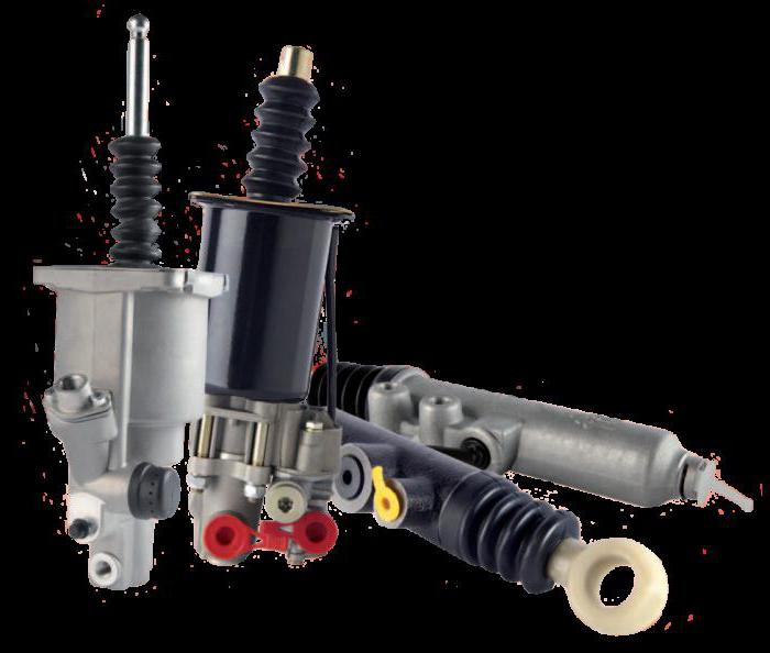
Amplifiers used on KamAZ
Structurally, KamAZ vehicles provide for the use of products of both domestic and foreign production. The operating principle of the mechanisms is identical; the devices differ in characteristics and design.
- Thus, the 5320 amplifier, produced at the Kama plant, structurally uses a vertical arrangement of the follower mechanism; the pneumatic cylinder is also installed vertically. Such devices are used on modifications: 5320, 4310, 43118, etc.
- The WABCO amplifier is manufactured in the United States of America. The product is distinguished by its compact size and lining wear indicators, which facilitates the use of the PGU. Similar devices are used on new KamAZ vehicle models: 5460, 6450, 6460, 65117, etc. The amplifier is compatible with “154” series gearboxes, which are used with power units that meet Euro-2 and Euro-3 standards.
- PGU "WABCO" for KamAZ modifications: 6460, 6520 and other equipment with ZF gearboxes.
- PGU "WABCO" for modifications of KamAZ: 4308, on which a ZF five-speed gearbox is installed.
- CCGT units made according to the “WABCO” type are produced in Ukraine and Turkey.
Read also: Symbols on the Sherkhan alarm key fob
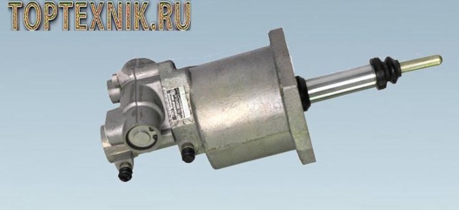
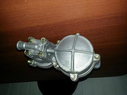
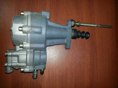
PSU for KamAZ 5320:
CCGT maintenance and repair issues
Maintenance of the pneumatic-hydraulic booster is carried out during maintenance of the vehicle’s clutch. The PSU should be inspected for breakdowns, oil leaks and air leaks, tighten the fastening bolts, and then adjust the free play of the PSU pusher, this is done by tightening and unscrewing the spherical nut (this value is not the same in different models of amplifiers and gearboxes, usually this parameter is specified in the instructions ) Be sure to replenish the level of working fluid in the reservoir of the hydraulic clutch drive system.
If the CCGT is replaced, the following actions should be taken:
- Release the existing air from the pneumatic circuit of the brake drive (to do this, open the valve on the receiver);
- Remove the spring that provides pressure on the clutch fork shaft lever;
- Disconnect the air supply pipe from the pneumatic system from the PGU;
- Disconnect the working fluid supply tube from the CCGT unit (it is recommended to completely drain the liquid from the system);
- Remove the amplifier.
When disassembling the CCGT, the condition of its parts is checked, special attention is paid to the sealing elements (if cracks, swelling, loss of elasticity and damage are detected, they are replaced), as well as the condition of the working surfaces of the cylinders - they should not have cracks, burrs, dents, etc. d. Additionally, the compliance of the actual internal diameter of the cylinders and its compliance with the tolerances specified in the instructions is checked.
A repaired or new PGU is installed in place in the reverse order; after installing the hydraulic and pneumatic pipelines, brake fluid is poured into the clutch drive system and pumped. Then the hydraulic system and pneumatics are checked for leaks.
Typically, the pneumatic-hydraulic clutch booster serves for many years without causing any problems, and in the event of a breakdown, it is most often easier to replace them as an assembly. With proper vehicle operation and timely maintenance, the PPU will work for a long time and reliably even in the most difficult conditions.
source
How to adjust
By adjustment we mean changing the free play of the clutch release clutch. The clearance is checked by moving the fork lever away from the spherical surface of the booster pusher nut. The operation is carried out manually; to reduce the force, it is necessary to remove the lever spring. A stroke of 5-6 mm (measured at a radius of 90 mm) is normal. If the measured value is within 3 mm, then it should be brought to normal by rotating the spherical nut.
After adjustment, you need to check the full stroke of the pusher, which should be at least 25 mm. The test is performed by fully pressing the clutch pedal.
At lower values, the amplifier does not ensure full disengagement of the clutch discs.
Additionally, the free play of the pedal is adjusted, corresponding to the start of operation of the master cylinder. The value depends on the gap between the piston and the pusher. A normal travel range is 6-12mm, measured across the middle of the pedal. The gap between the piston and the pusher is adjusted by turning the eccentric pin. The adjustment is performed with the clutch pedal fully released (until it contacts the rubber stop). The finger rotates until the required free play is obtained. Then the nut on the regulator is tightened and the safety pin is installed.
Read also: Kinokopilka pro new address