content .. 51 52 59 ..
Chapter 5
BRAKE SYSTEMS FOR MAZ-64227, MA3-54322 CARS
Device
The vehicles are equipped with service, parking, spare and auxiliary brake systems, as well as brake devices for connecting the brake system of a semi-trailer with one- and two-wire pneumatic drives and outputs for supplying other consumers with compressed air.
The service brake system acts on the brake mechanisms of all wheels of the car. The drive mechanisms are pneumatic with separate braking of the front and rear wheels.
The parking and spare brake systems act on the brake mechanisms of the middle (for the MAZ-64227) and rear axles, which are activated using brake chambers with spring energy accumulators. Control is carried out using a crane in the driver's cabin.
The parking brake system also serves as a backup brake system, which is designed to brake the vehicle in the event of a complete or partial failure of the service brake system.
When the parking brake system is activated, the control valve handle is set (by turning) to its extreme fixed position. The compressed air that compresses the power springs of the energy accumulators is released into the atmosphere, and the springs activate the brake mechanisms.
When the emergency brake system is activated, the parking brake control valve handle is held in any intermediate non-fixed position.
As the angle of rotation of the handle increases, the braking intensity increases due to a decrease in air pressure compressing the springs of the energy accumulators.
The auxiliary braking system acts on the vehicle's transmission by creating back pressure in the exhaust system using a pneumatically driven throttle valve and is designed to slow down the vehicle on long descents of mountain roads. When turning the valve, the fuel supply is simultaneously turned off.
When the tractor vehicle is braked by the working or parking (spare) systems, the semi-trailer is simultaneously braked. Braking of the semi-trailer MA3-9398 and MA3-9389 also occurs when the auxiliary brake system of the MAZ-64227 vehicle is turned on.
Brakes
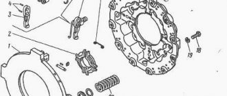
Drum type (see Fig. 57 and 72), with two internal shoes. Brake linings measuring 420x160xx17 are attached to the pads with brass rivets. The brake drum 29 (see Fig. 57) is attached to the wheel hub 17 with bolts 30. At the end of the expansion knuckle shaft 24 there is a worm-type adjusting lever (Fig. 92) connected to the brake chamber rod.
To prevent lubricant from entering the brake mechanisms in the expansion brackets
The front and rear brake cams are equipped with rubber O-rings.
Diaphragm brake chambers are designed to activate the brake mechanisms of the front wheels of a car when the service brake system is activated.
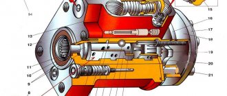
Brake chambers with spring energy accumulators (Fig. 93) are designed to activate the brake mechanisms of the wheels of the rear and middle (for MAZ-64227) axles when the service, parking and spare brake systems are activated.
When the service brake system is turned on, the brake mechanisms are actuated by the rods of 10 diaphragm brake chambers, the design and operating principle of which are practically no different from the front brake chambers.
When the parking brake system is turned on, compressed air is released from the cavity under the piston 6. The piston, under the action of the power spring 7, moves down and moves the pusher 4, which, through the thrust bearing 9, acts on the diaphragm 3 and the brake chamber rod 10, resulting in the vehicle braking.
When the parking brake system is turned off, compressed air is supplied under the piston 6, which, together with the pusher, moves upward, compressing the spring and allowing the brake chamber rod to return to its original position under the action of the return spring 1.
When braking by the reserve system, the air from the cylinders of the energy accumulators is not completely released, but only to the extent of the required braking efficiency of the vehicle, which corresponds to the intermediate positions of the control valve handle. Thus, the braking efficiency depends on the angle of rotation of the crane handle.
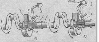
The mechanism of the throttle-type auxiliary brake system (Fig. 94) with a damper installed in the engine exhaust pipe in front of the muffler consists of a housing
1 and the damper 2, fixed to the axis 3. The rotary lever 4, connected to the rod of the drive pneumatic cylinder, is also fixed to the damper axis. Lever 4 and associated damper
2 have two fixed positions. When the auxiliary brake is turned off, the damper is installed along the exhaust gas flow, and when the brake is applied, it is perpendicular to the gas flow, creating back pressure at the exhaust. At the same time, the fuel supply is turned off using a pneumatic cylinder connected to the engine stop bracket.
The pneumatic cylinder (Fig. 95) is designed to control the flap of the auxiliary brake system mechanism. When the auxiliary brake system is turned on, compressed air enters the space above the piston and, overcoming the resistance of the return springs, moves the piston and rod 8, which is connected to the damper control lever of the mechanism. The piston returns to its original position under the action of the return spring.
Rice. 92. Adjustment lever: 1 - body; 2 cover; 3 - worm; 4 - gear; 5 — locking plate; 6 - bolt
content .. 51 52 59 ..
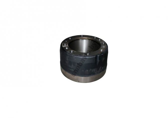
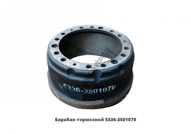
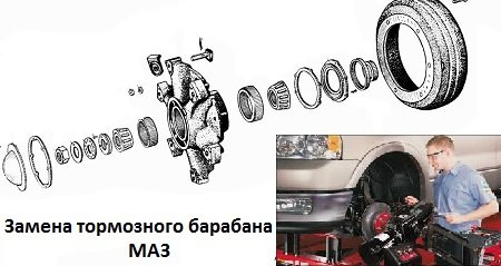
Brake drum structure:
The part is a cylinder with a conical part. The wide side of the drum has a collar with holes for pins. Depending on the model and modification of the MAZ, the type of drum and its weight, there are from 6 to 12 holes. For dismantling, there are 2 threaded holes located below the mounting holes; they have a diameter suitable for M16 threads.
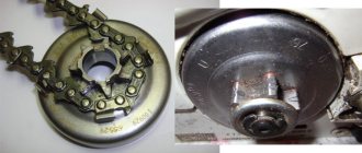
How does a drum brake system
? There are brake pads inside the MAZ drum. During movement, they are diverted from the drum and, when the driver presses the brake pedal, compressed air from the receivers enters the brake chambers. The pistons of the brake chambers move from the pressure and push the adjustment lever and, as a result, the pads are pressed against the brake drum and reduce the speed of the MAZ.
Removing and replacing the MAZ brake drum:
The removal process is as simplified as possible, which allows you to change them both in the garage and on the road. From the tools we need a wrench for unscrewing the wheel bolts and a wrench for screwing the bolts into the dismantling holes.
Drum removal procedure:
- Raise the wheel with a jack;
- Remove the wheel;
- Screw the bolts to separate the drum from the hub into the dismantling holes;
- Take your time, slowly and evenly screw in the bolts until the drum is removed.
Installation must be done in reverse order. The only difficulty is the weight of the drum from 40 to 70 kg, so we recommend getting an assistant or a winch (any other lifting device for heavy objects).
Monitor and promptly change drums for your safety and the safety of others. You can buy a high-quality and certified MAZ brake drum with a guarantee on our website or call: + 375 (17) 380-23-72; + 375 (29) 747-80-78.
| Brake drum 4370 front 8 holes for lining 120mm, 42858 | 4370-3501070 |
| Brake drum 4370 (8 holes, 120mm for lining) front, made in the Russian Federation 5354 | 4370-3501070 | |
| Front brake drum 8 holes. for overlay 150mm, MAZ, 42859 | 4370-3502070 |
| Rear brake drum 8 holes lining 150mm, made in Russia, 4381 | 4370-3502070 | |
| Brake drum MAZ-5551.5336 (12 holes, 160mm for lining), 411 | 5336-3501070 |
| Brake drum (160mm lining, 12 holes), made in the Russian Federation, 43344 | 5336-3501070 | |
| Brake drum with 10 holes for lining 220mm, MAZ OJSC, 43939 | 5440-3502070 |
| Brake drum 5440-3502070 (RF), 5550 | 5440-3502070 | |
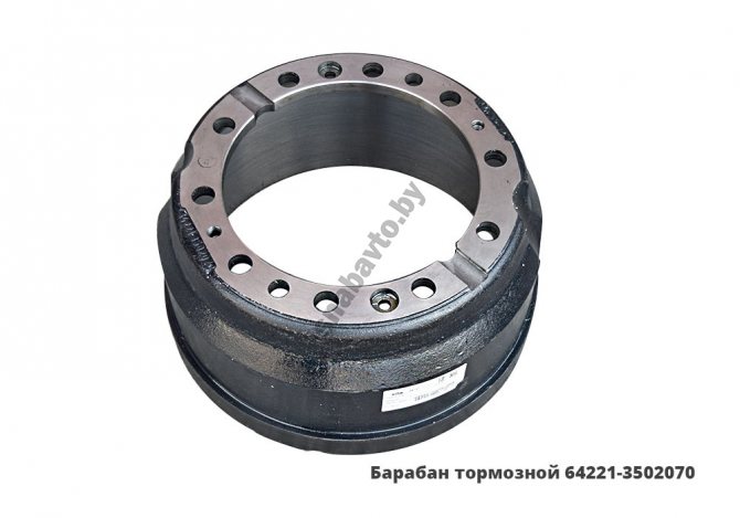
| Drum brake lining 160mm, 10 holes, manufactured by MAZ OJSC, 42862 | 64221-3502070 |
| Brake drum (lining 160mm, 10 holes), made in Russia, 1912 | 64221-3502070 | |
| Brake drum 10 holes overlay 180mm, MAZ OJSC, 4616 | 6430-3501070 |
| Brake drum 6430-3502070, 4188 | 6430-3502070 | |
| Brake drum 6430-3502070 (RF), 38032 | 6430-3502070 | |
| Brake drum 9397-3502070, 773 | 9397-3502070 |
Types of MAZ brake drums:
Brake rams are divided into 4 groups:
- Rear axle drums;
- Front axle drums;
- Universal drums for rear and front wheels;
- Semi trailer drums
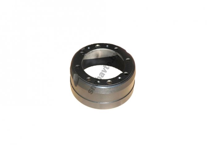
The vast majority of MAZ vehicles are equipped with different drums for the front and rear axles. Drums are also divided by standard size - the internal working diameter on trucks, trailers and semi-trailers = 420mm, and on the MAZ "Zubrenok" drums with a diameter of 325mm are installed. The width of the brake pad lining can be from 100mm to 220mm. (100, 140, 145, 160, 200, 220).
The weight of brake drums reaches up to 70 kg, due to their manufacturing from gray cast iron using the stamping method. Thanks to the properties of this material, a high coefficient of friction and effective braking are ensured.
Maintenance
The brake drum for MAZ 4370 is included in the device:
- Parking system;
- Working system;
- Spare system;
- Assistive system.
As a rule, the part is very durable. Special production technologies can increase the service life of truck suspension parts.
However, no matter how strong the unit is, remember that the condition of the MAZ brake drum directly affects the safety of movement.
The spare part requires regular maintenance and care. It is necessary to monitor the condition of the part and carry out timely repairs.