Spare parts for truck cranes Galician
| Name | Index | Applicability | Price, rub.) |
| Truck crane drilling rig ABU-8000 | ABU-8000 | for all models of Galician truck cranes | 1 590 000 |
| Truck crane installation cradle (basket) AML-250 (g/p 250 kg.) | AML-250 | for all models of Galician truck cranes | 154 000 |
| Oil tank | KS-65721-2.83.320; -01 | KS-65721 | 76 582 |
| Oil tank | KS-65713-1.83.300-1 | KS-65713 | 153 164 |
| Oil tank | KS-55729V.83.300 | KS-55729V | 55 696 |
| Oil tank | KS-55713-1V.83.300-1; -01 | KS-55713V | 55 696 |
| Oil tank | KS-55713-1.83.300-3 | KS-55713 | 46 506 |
| Rear beam | KS-65721.30.300 | KS-65721 | 292 404 |
| Rear beam | KS-65713-1.30.300-1 | KS-65713 | 264 556 |
| Rear beam | KS-55715.30.600-1 | KS-55729-1V;-5V | 97 468 |
| Rear beam | KS-55715-5.30.600 | KS-55729V | 69 620 |
| Rear beam | KS-55713-5V.30.600 | KS-55713V | 69 620 |
| Rear beam | KS-55713-1V.30.600-1 | KS-55713V | 97 468 |
| Rear beam | KS-55713-1.30.600 | KS-55713 | 65 652 |
| Drum assembly | KS-55713-1.26.100-1 | KS-55713 | 88 209 |
| Shoe | KS-4572A.63.272 | KS-55713 | 850 |
| Shoe | KS-4572.63.106 | KS-55713, KS-65713 | 1 150 |
| Shoe | KS-4572.63.105 | KS-55713 | 1 000 |
| Block | KS-55713-1V.63.190-1-01 | KS-55713V | 8 354 |
| Block | KS-55713-1V.63.190-1 | KS-55713V | 8 354 |
| Block assembly KS-55721.64.340 | Block assembly KS-55721.64.340 | KS-55721 | 4 200 |
| Valve block | KS-45721.84.600-01 | modifications | 9 200 |
| Valve block | KS-4572.84.600 | modifications | 6 700 |
| Valve block Rexroth 052117 (replaces KS-4572.84.600) | KS55713-1.84.600 | modifications | negotiable |
| Block KS-4572.63.341 (315*150) steel | Block KS-4572.63.341 (315*150) steel | KS-4572, KS-55713, etc. | 3 960 |
| Block KS-45721.63.341 (315*125) | Block KS-45721.63.341 (315*125) | KS-4572, KS-55713, etc. | 3 250 |
| Block KS-45722.63.256-3 (315*125) | Block KS-45722.63.256-3 (315*125) | KS-4572, KS-55713, etc. | 3 250 |
| Pull block block (polyamide) (315*130*50) | Pull block block (polyamide) 315*130*50 | KS-55729-1V | 3 000 |
| Pull block block (polyamide) 315*125*58 | Pull block block (polyamide) (315*125*58) | KS-55713-1V, KS-55713-1K3 | 3 000 |
| Safety valve block | Safety valve block BOPC 25.20 | modifications | 23 400 |
| Spring block assembly DDS | Spring block assembly DDS | Boom length sensor (DDS) | 6 500 |
| Control lever block | KS-65713-1.70.100-2 | KS-65713 | 37 177 |
| Control lever block | KS-55713 70.100-1 | KS-55713, KS-55713V, KS-55729V | 13 367 |
| Pull block blocks | KS-74713.00.530 (polyamide) single block. | KS-74713 | 2 924 |
| Pull block blocks | KS-74713.63.330 (steel) suspension brackets. | KS-74713 | 16 709 |
| Pull block blocks | KS-74713.63.230 (polyamide) fire boom | KS-74713 | 15 316 |
| Pull block blocks | KS-65721.63.330 (steel) | KS-65721, KS-75721 | 13 924 |
| Pull block blocks | KS-65721.63.230 (polyamide) | KS-65721, KS-75721 | 6 962 |
| Pull block blocks | KS-65713-1.63.210 (steel) | KS-65713 | 13 228 |
| Pull block blocks | KS-55721.63.220 (steel) | KS-55729V | 5 709 |
| Pull block blocks | KS-55721.63.220-1 (polyamide) | KS-55729V | 4 177 |
| Pull block blocks | KS-55713-1V.63.340-1 (polyamide) | KS-55713V, KS-65721, KS-75721 | 4 734 |
| Pull block blocks | KS-45721.63.340 (steel) | modifications | 5 848 |
| BOD-00 | BOD-00 | Data processing unit ONK-140 | 79 200 |
| FIGHTS | FIGHTS | Information processing unit ONK-160 | 80 000 |
| Shaft | KS-55713-6.14.109 | KS-55713, KS-65713 | 5 987 |
| Shaft | KS-55713-6.14.101 | KS-55713, KS-65713 | 4 873 |
| Shaft | KS-55713-3.14.105 | KS-55713 | 2 785 |
| Shaft | KS-45719-1.14.109 | KS-55713 | 3 829 |
| Cardan shaft | KS-4572A.14.400 | KS-55713 | 4 838 |
| Cardan shaft UAZ-469 front drive KOM | Cardan shaft UAZ-469 front drive KOM | KS-55713 | 3 900 |
| Shaft KS-2574.28.193 | Shaft KS-2574.28.193 | KS-45724, KS-55713 | 1 950 |
| Upper section | KS-55713-1.63.700 | KS-55713 | negotiable |
| Fork | KS-55713-1.14.370 | KS-55713 | 3 063 |
| Fork | KS-4572.14.350 | KS-55713 | 1 392 |
| Sleeve | KS-65713-1.64.521 | KS-65713 | 9 051 |
| Sleeve | KS-55713-6.14.102 | KS-55713 | 5 152 |
| Bushing OSK | KS-65713-1.26.003 | KS-65713 | 209 |
| Boom base bushing for Galician truck cranes KS-4572, KS-45719, KS-55713 | KS-4572A.63.592-1 | modifications | 4 500 |
| Switch (sensor) VB2A.30M.53.10.3.1.K | Switch (sensor) VB2A.30M.53.10.3.1.K (ISB AF8A-32-P-10G-LZT2-CP) | Contactless switch | 900 |
| Switch (sensor) VB2A.40.ХХ12.1.1 | Switch (sensor) VB2A.40.ХХ12.1.1 | Contactless switch | 900 |
| Contactless switch VBI-M30-76U-1113-3 | Contactless switch VBI-M30-76U-1113-3 | Contactless switch | 900 |
| Switch VP 15K21A231-54 U2.8 | Switch VP 15K21A231-54 U2.8 | Track switch | 850 |
| Switch VPK 2111 BU2 | Switch VPK 2111 BU2 | Track switch | 500 |
| Switch VPK-2110 | Switch VPK-2110 | Track switch | 500 |
| G/lock 541.08.00 | G/lock 541.08.00 | KS-55713 and others. | 3 500 |
| G/lock (type 83.200.83.280) Italy | G/lock (type 83.200.83.280) Italy | KS-55713 | 3 200 |
| G/lock 541.12.00 | G/lock 541.12.00 | KS-65713 and others. | 4 500 |
| G/lock P-788 A | G/lock P-788 A | KS-55713 and others. | 3 500 |
| G/regulator valve 94.030 | G/regulator valve 94.030 | modifications | 11 500 |
| G/regulator valve GKR.20.160.25 (Safety valve) | G/regulator valve GKR.20.160.25 (Safety valve) | modifications | 16 700 |
| G/distributor Q130 F7SR (2 sections) | G/distributor Q130 F7SR (2 sections) | Basic Operations Distributor | 49 500 |
| G/distributor Q160 (4 sections) | G/distributor Q160 (4 sections) | Basic Operations Distributor | 90 500 |
| G/distributor Q75/5E(5 sections) | G/distributor Q75/5E(5 sections) | Outrigger control distributor | 29 000 |
| G/distributor Q80 F7SR (2 sections) | G/distributor Q80 F7SR (2 sections) | Basic Operations Distributor | 49 800 |
| G/distributor GMZ Bulgaria (5 sections,) 40 l. | G/distributor GMZ Bulgaria (5 sections,) 40 l. | Outrigger control distributor | 18 000 |
| G/distributor GMZ Bulgaria (5 sections,) 80 l. | G/distributor GMZ Bulgaria (5 sections,) 80 l. | Outrigger control distributor | 18 000 |
| G/distributor GR 2-3 (12V) | G/distributor GR 2-3 (12V) | Accelerator valve | 2 900 |
| G/distributor GR 2-3 (24V) | G/distributor GR 2-3 (24V) | Accelerator valve | 2 900 |
| G/distributor PM 20-33; | G/distributor PM 20-33; | Basic Operations Distributor | 41 600 |
| G/distributor RM-20-01; | G/distributor RM-20-01; | Basic Operations Distributor | 38 000 |
| G/distributor RM-20-02 | G/distributor RM-20-02 | Basic Operations Distributor | 38 000 |
| G/distributor PM12-100 | G/distributor PM12-100 | Outrigger control distributor | 25 600 |
| G/distributor RX 346 1ZHZHZHZH-4 (6 sections) | G/distributor RX 346 1ZHZHZHZH-4 (6 sections) | Outrigger control distributor | 31 000 |
| G/distributor 1 PE (BE) 6 574 EG 24NM | G/distributor 1 PE (BE) 6 574 EG 24NM | Electrohydraulic distributor 1el.mag. | 3 800 |
| G/distributor 1 PE(BE) 6 573 EG 24N | G/distributor 1 PE(BE) 6 573 EG 24N | Electrohydraulic distributor 1el.mag. | 3 900 |
| Hydraulic lock (type 83.200.83.280) Italy | 83.200.83.280 | KS-55713 | 3 500 |
| Hydraulic lock 541.08.000 | 541.08.000 | KS-55713 and others. | 3 150 |
| Hydraulic lock 541.12.000 | 541.12.000 | KS-65713 and others. | 5 200 |
| Hydraulic lock HBS A0504520100\01\06\13 | Hydraulic lock HBS A0504520100\01\06\13 | KS-65713,65719,55713-1V,55713-1K3 | 6 300 |
| Hydraulic lock VBPS01M14 | Hydraulic lock VBPS01M14 | KS-55713 and others. | 3 000 |
| Cargo winch hydraulic motor (adjustable) | Hydraulic motor 303.3.112.501 | modifications | 76 500 |
| Cargo winch hydraulic motor (adjustable) | Hydraulic motor 303.4.112.503 | modifications | 76 500 |
| Hydraulic motor of cargo winch MBV 10.4.112.501.002BN | analogue 303.3.112.501 | modifications | 84 500 |
| Hydraulic motor of cargo winch MBV 10.4.112.503.0.00.0BN | analogue 303.3.112.503 with valve will speed up. | modifications | 84 500 |
| Hydraulic motor of cargo winch MBV 10.4.112.901.0.02BN | analogue 303.3.112.501 | modifications | 84 500 |
| Swing motor | Hydraulic motor 310.4.112.00.06 | modifications | 38 500 |
| Hydraulic pump MBF 10.4.112.00.06N | analogue 310.4.112.00.06 | modifications | 38 500 |
| Hydraulic pump MBF 10.4.56.00.06N | analogue 310.4.56.00.06 | modifications | 24 500 |
| Hydraulic pump for PTO drive and turning mechanism | Hydraulic pump 310.3.56.04.06 | modifications | 24 900 |
<< 1 2 3 4 5 > >>
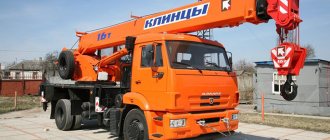
SPARE PARTS FOR GALICHANIN MOTOR CRANES
Our
, is engaged in the manufacture and supply of spare parts for truck cranes of the
“GALICHANIN”
(JSC “GALICH AUTO CRANE PLANT”), the main brands are
KS-4572A,
KS-55729,
KS-55713,
-45719,
KS-65713-1,
KS-65721,
KS-65721-6
, and is also a service and consulting center for working with enterprises that repair automotive lifting equipment.
Almost 100% availability of parts in stock!
We deliver spare parts ordered from us in the shortest possible time through transport companies, LLC “Business Lines”, LLC “PEK”, LLC “KIT” in all regions of Russia!
Hydraulic system filter for truck crane Ivanovets, Galician. Excavator EK-12, EK-14, EK-18, EO-4225
Hydraulic system filter for Truck crane Ivanovets, Galichanin, Klintsy. Excavators: EO3323A, EK12…..18. Analogue of the standard filter element Regotmas-661
The hydraulic system filter is used on truck cranes: Ivanovets, Galichanin, Klintsy, Chelyabinets. Excavators: EO3323A, EK12-18
Repair kits for all hydraulic cylinders are also available.
We work only directly with manufacturers throughout Russia, which allows us to ensure the availability of a full range of original spare parts for truck cranes “Ivanovets”, “Galichanin”, “Klintsy”, “Uglichmash”, “Chelyabinets”, etc. from leading manufacturers at the lowest prices prices.
You can purchase at competitive prices almost any spare parts for domestic truck cranes related to the hydraulic drive of the truck crane (pumps, hydraulic motors), elements of the fixed part of the truck crane (fixed frame), rotating frames with mechanisms, boom equipment, control drives for crane operations, electrical equipment, safety devices (OGM240 -18, OGM240-14, ONK-M, ONK-140, ONK-160) for crane and much more.
Possessing a large warehouse of spare parts and a developed supply network, our company quickly fulfills any need for spare parts for truck cranes, including complex ones of any complexity. An individual approach, reasonable prices, a quality system, a guarantee, a flexible system of discounts for both old partners and new companies are the key to long-lasting and uninterrupted operation of your equipment.
• Quality and reliability of spare parts! All spare parts and components for truck cranes supplied by the company are certified, which guarantees quality and reliability in operation.
Spare parts for truck cranes: Hydraulic cylinders, Hydraulic distributors, Hydraulic motors, Hydraulic pumps, Pipeline connection, Rotating joint, High pressure hoses, Hydraulic valves, rubber goods, Slewing bearing (SPU), Swing mechanism, Cargo winch gearbox, Boom base, Boom sections, Suspension locking mechanism , Power take-off (PTO), Anemometers, Load limiters TURNING MECHANISM Rotation mechanism for the Galichanin truck crane (reducer) KS-2574.28.100-1-02G Rotation mechanism for the Klintsy truck crane (gearbox) KS-2574.28.100-1-03K Rotation mechanism for the Ivanovets truck crane (gearbox) KS-3577.28.000 Rotating mechanism of the Ivanovets truck crane (gearbox) KS-3577.28.000-1 Lower part of the housing of the rotating mechanism KS-3577.28.102 (KS-2574.28.202) Upper part of the housing of the rotating mechanism KS-3577.28.081 ( KS-2574.28.181) Splined shaft KS-3577.28.093-3 (16 x 16) for the turning mechanism of the truck crane Splined shaft KS-3577.28.093-2 (16 x 14) for the turning mechanism of the truck crane Gear shaft KS-3577.28.101-1 Shaft - gear (turnkey) KS-3577.28.073-3 Rotation mechanism cover KS-3577.28.087-2, KS-2574.28.187-1 Half coupling KS-3577.28.104, KS-2574.28.204 Gear wheel KS-3577.28. 083-3, KS-35716.28.183 Gear wheel KS-3577.28.097-3, KS-35716.28.197 Brake release KS-3577.28.200, KS-2574.28.500 Output shaft gear (13 teeth. ) KS-3577.28.092 Output shaft gear (14 teeth) KS-45717.28.101, KS-4572.28.101 Brake pulley KS-3577.28.126 (KS-35716.28.102) Brake pulley KS-2574.28.234 Brake shoe KS- 3577.28.030 (KS-2574.28.130) Swing brake pulley KS-3577.28.126-1 for KS-3577, 45717 Swing gear reducer KS-45721.28.00.1000-01 for KS-45721 Swing brake release KS-45721. 28.00.1300 Swing brake pulley KS-3577.28.134 Ф=35mm Bearing (swing mechanism) 1606, 217, 3614 Bearing for fastening the boom lift hydraulic cylinder ShSL-90K1 HYDRAULIC EQUIPMENT Two-way crane KS-55713-1.83.280 for Galician truck crane KS-4572A, KS-557 13 Crane two-way valve U.034.00.000-11 for KS-35714, KS-35715, KS-45717 Two-way valve U034.00.000-9 for Ivanovets truck crane KS-3577, KS-3574 Two-way valve U034.91.000-9 for truck crane Two-way valve KS-45721.31 .770-01 truck crane Chelyabinets KS-45721 Hook tightening crane S-45721.70.23.00 truck crane Chelyabinets KS-45721 Two-way crane Galtech GE G3/4 truck crane Galician KS-55713 Hydraulic lock KS-4572A.84.380 truck crane Galician Hydraulic lock 5 41.08.00 (P788A) truck cranes Galichanin, Ivanovets Hydraulic lock of support 541.12.00 of truck cranes Galichanin, Ivanovets Hydraulic lock KS-3577.83.200 of truck crane KS-3577, KS-3574, KS-35714, KS-35715 Hydraulic lock KS-45717.31.400 of truck crane Ivanovets KS-4 5717, Chelyabinets KS-45721 Hydraulic lock U4610.36B for the hydraulic cylinder for lifting the boom of a truck crane KS-45717 Hydraulic lock of the support KS-3577.83.200 Hydraulic lock of the support MKAT-20, KS-4572A, KS-4573 P-788A.5.09.0063 Pneumatic distributor PR 2-3 (24v. ) (electric pneumatic valve) Rotating connection KS-4572.83.500 of the Galician truck crane KS-4572 Rotating connection KS-55713-1.83.500 of the Galician truck crane Rotating connection KS-55713-1K.83.500 of the Klintsy truck crane Rotating connection KS-3577.83.300 of the truck crane I vanovets KS-3574 Rotating connection KS-35714.83.300 of the Ivanovets truck crane Rotating connection KS-35714.83.300-1-01 of the KS-45717 truck crane Rotating connection KS 35714.83.300-01, KS 35714.83.300-02 Set of support pipelines KS-3574.31.06 0-10 truck crane KS-35715, KS-35714 Set of pipelines KS-45717.31.060-10 for a truck crane Ivanovets KS-45717 Set of pipelines KS-3577.83.050-1 for the supports of a truck crane Ivanovets Set of pipelines for supports KS-35714.31.060-10 for a truck crane Ivanovets Set of pipelines for you mobile supports (32 pcs.) KS-35714.31.600 Set of pipelines for retractable supports KS-35714, KS-35715, KS-45717 Set of pipelines for retractable supports KS-3577, KS-3574, KS-5576 Set of pipelines KS-4572A.31.060- 10 for KS-4572, KS-55713 Pipeline set for truck crane Drogobych KS-3575A (ZIL-133GYA) Pipeline kit for truck crane Chelyabinets KS-45721, KS-55733, KS-65711 Pipelines for truck crane Galichanin, Klintsy, Ivanovets BOOM EQUIPMENT, STR ELA Boom base KS-45719-2.63.500-1, KS-55713-1.63.500 truck crane Galichanin Middle boom section KS-45719-1.63.600, KS-55713-1.63.600 Galichanin Upper boom section KS-4572A.63.700, KS-55713 -1.63.700-1 Auto-Crane The Telescopic arrow KS-45721B.63.10.000-01 Autocrane KS-45721 The foundation of the boom KS-45721B.63.16.000-01 Autocrane KS-45721 Upper section of the arrows KS-45721v.63.40 -45721 Middle boom section KS-45721В.63.30.000 of the Chelyabinets KS-45721 truck crane Boom base 700.12.63.500 of the Chelyabinets KS-55730 truck crane Middle boom section 700.12.63.600-01 of the Chelyabinets KS-55730 truck crane Upper boom section 70 0.12.63.700 truck crane Chelyabinets KS- 55730 Boom 700.12.63.100 of the Chelyabinets KS-55730 truck crane Hook suspension KS-55713-1B.63.300 of the Galichanin truck crane with a capacity of 25 tons Hook suspension of the jib KS-4572A.62.300 of the Galician truck crane Hook clip KS-3577-3. 63.300 truck crane Ivanovets KS-3577 , KS-3574 Hook suspension KS-55730.63.300 for truck crane Chelyabinets KS-55730 Rope block KS-45721.63.340 for truck crane Galichanin, Klintsy Rope block KS-4572.63.331 for truck crane Galichanin KS-4572A cast iron Rope block KS-3 577.63.271 truck crane Ivanovets KS -3577, KS-3574 Pulley block (cast iron) KS-3577.63.271 for KS-3574, KS-3577 Steel block KS-3577.63.271-2 for Ivanovets truck crane KS-3577, KS-3574 Steel block U2.24.63.026- 3 Autocrans KS-35714, KS-35715, KS-45717 Police Police KS-45721A.63.34.001-01 (polyamide) for KS-45721 Police KS-4561A.302.00.010 for autocrane KS-4561A Kolisposta KS-45717.61.61 .161 truck crane Ivanovets Pull block U2.24-63.026 Front carriage KS-3577.63.150 truck crane Ivanovets KS-3577, KS-3574 Rear carriage KS-3577.63.240-1-10 truck crane Ivanovets KS-3577, KS-3574 Boom base axis KS-4572.63.020 of the Galichanin truck crane Bushing of the boom base axis KS-4572A.63.592-1 of the Galician truck crane Boom base axis KS-45721.63.020 of the Chelyabinets truck crane KS-45721 Boom base axis KS-45724-8.63.040 of the Klintsy truck crane Bushing of the base axis booms KS -45724-8.63.562 truck crane Klintsy Boom base axis KS-3577.63.001-1, KS-45717.63.003 truck crane Ivanovets Boom lift hydraulic cylinder axis KS-3577.63.012, KS 45717.63.005 Boom base axis KS 35714.63.003 , KS- 35715.63.001 of a truck crane Extension rope for the upper boom section KS 45717.61.130 of a truck crane Retraction rope for the top boom section KS 45717.61.140-01 of a truck crane Cable 16.5 mm x 88 m for Ivanovets truck crane KS-3577, KS-3574, KS-45717 Set ect slabs sliding plates for truck crane Galichanin KS-55713, KS-4572A Set of sliding plates for truck crane Klintsy KS-45719, KS-55713 Set of sliding plates for truck crane Ivanovets KS-35715 (3 sections. ) Set of sliding plates, sliders KS-4574 Kamyshin Sliding plate KS-4572A, KS-45719, KS-45721, KS-55713, KS-55715 Sliding plate for Chelyabinets truck crane KS-45721, KS-55730, KS-65711 Sliding plate, slider KS-35714, KS-35715, KS-45717, KS-6973B Sliding plate, sliders MKT-25, MKAT-25, MKB 30.5 “Ulyanovets” Sliding plate, sliders KS-35719-8-02, KS-45719, KS– 55713-1K Hook suspension KS-45717.64.300-01 CRANE OPERATOR'S CABIN Crane operator's cabin of the Ivanovets U 7810.5-01 truck crane Large windshield U7810.5.758 (780x665) of a truck crane Small windshield U7810.5.803 (780x362) truck crane Side door glass (large) U7810. 5.045 (830x778) of a truck crane Small side glass U7810.5.046 (830x395) of a truck crane Rear glass U7810.5.163 (670x610) of a truck crane Hatch glass U7810.5.604 (670x400) Large windshield glass 780x1005 “Chelyabinets” three plex Truck crane glass Ivanovets, Galichanin, Klintsy, Chelyabinets Glass for KS-3574, KS-3577, KS-35714, KS-35715, KS-45717, KS-45721, KS-55711 Truck crane operator's cabin Galichanin KS-55713.52.100-1-02 Glass set for truck crane operator's cabin Galichanin Truck crane operator's cabin Klintsy KS-45724.52.010; -01; -02 Crane operator cabin heater Planar-4DM 24V (diesel fuel) Heating unit O30-B4 (24 V petrol), truck crane heater Gasoline heater 030-0010-20 (24 V) (Gasoline) truck crane Diesel heater Planar 4D-24, truck crane heater Heater for truck crane Ivanovets, Chelyabinets, Galichanin, Klintsy, KS REMOTE SUPPORTS Remote support KS-55713-1.31.500-1 for truck crane Galichanin External support KS-55713.1K.31.500 for truck crane Klintsy KS-45719, KS-55713 Remote support KS-35719-3 -31.500 truck crane Klintsy KS-35719 Thrust bearing KS-45721.00.100 truck crane Galichanin KS-4572A, KS-55713 Thrust bearing KS-3577.00.100 truck crane Ivanovets KS-3577 Thrust bearing KS-3574.00.100 truck crane Ivanovets KS-357 4, KS-35714, KS -35715 Thrust bearing KS-45717.00.100 for truck crane Ivanovets KS-45717
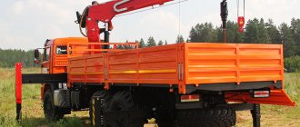
MANIPULATING CRANES, CMU UNITS, TRUCK CRANES
_____________________________________________________________________________________________
Hydraulic equipment of truck crane KS-55713
The hydraulic drive of the mechanisms of the KS-55713 Galician truck crane 25 tons on the KamAZ-65115 chassis is made according to an open single-pump hydraulic circuit and is designed to transfer energy from the chassis power unit to the hydraulic motors of the crane unit. The hydraulic circuit diagram is shown in Fig. 20.
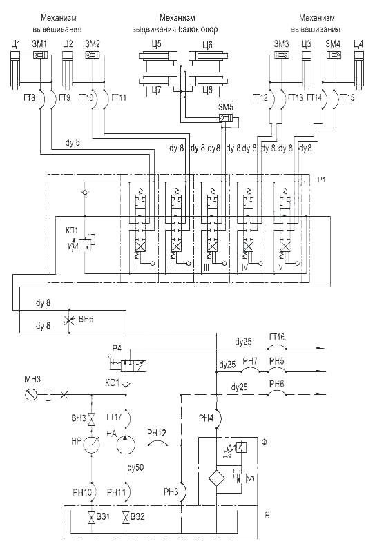
Rice. 20. Hydraulic schematic diagram of the fixed part of the KS-55713 automobile crane A - Rotating connection Dу = 25 mm KS-55713-1K.83.500 B - Oil tank V = 240 dm3 KS-55713-1K.83.300-1 VZ1 - Shut-off valve (in as part of the hydraulic tank) KS-55713-1K.83.320 VZ2 - Shut-off valve (as part of the hydraulic tank) VN1, VN2 - Valve Dу = 8 mm as part of the pipeline VN3 - Valve Dу = 6 mm as part of the pipeline VN4, VN5 - Valve Dу = 8 mm as part of the rotating connection VN6 - Valve-throttle Dу = 8 mm as part of the pipeline ГТ1...ГТ2 - Sleeve Dу = 12 mm, P nom=25 MPa RVD 12-25.0x650 GT4, GT6, GT7 - Sleeve Dу= 12 mm, P nom=25 MPa Hose 12-25x850 GT8... GT15 - Hose Dу= 12 mm, P nom=25 MPa Hose 12-25x1650 GT16...GT17 - Hose Dу = 25 mm, P nom=25 MPa Hose 25-25x580 GT18 - Hose Dу = 25 mm, P nom = 25 MPa RVD 25-25x400 GT20, GT21 - Hose Dу = 8 mm, P nom = 25 MPa RVD 8-25x700 RN1... RN9 - Hose Dу = 32 mm, R nom = 1.6 MPa 32x43 -1.6 РН10 — Sleeve Dу = 25 mm, Р nom=1.6 MPa 25х35-1.6 РН11 — Sleeve Dу = 50 mm, Р nom=1.6 MPa 50х61.5-1.6 РН12 — Sleeve Dу = 12 mm, P nom = 1.6 MPa 12x20-1.6 DR1 - Throttle Dу = 1 mm KS-2574.83.304 DR2 - Throttle Dу = 3 mm KS-2574.83.304-04 DR3...DR8 - Throttle Dу = 0 ,6 mm KS-2574.83.304-02 ZM1...ZM5 - One-way hydraulic lock Dу = 8 mm, P nom = 25 MPa 541.08.00 KI1, KI2 - "OR" valve KS-2574.84.450 KO1 - Check valve Dу = 20 mm , P nom=20 MPa KS-35719-3.83.400 KP4, KP5 - Block of non-return safety valves Dу = 25 mm, Pnom= 5...16 MPa КТ1 - Brake valve Dу = 16 mm, P nom=32 MPa
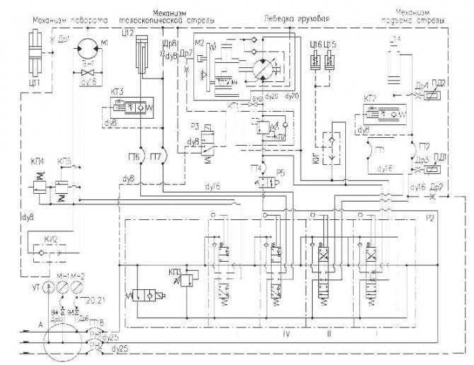
Rice. 21. Schematic hydraulic diagram of the rotating part. Operation of the hydraulic equipment of the KS-55713 truck crane. The mechanical energy of the chassis engine is converted by the pump “NA” (Fig. 20) into the energy of the working fluid flow, which is directed through the pipeline system to the hydraulic motors of the actuators. In the hydraulic motors of the actuators, the energy of the working fluid is again converted into mechanical energy. The speed control of the hydraulic motors of the KS-55713 automobile crane is combined - done by changing the rotation speed of the pump shaft (by changing the rotation speed of the chassis engine crankshaft) and throttling the working fluid in the channels of the hydraulic distributors. The use of an adjustable axial piston hydraulic motor in the drive of the load lifting mechanism makes it possible to additionally regulate the rotation speed of the cargo winch drum by changing the working volume of the hydraulic motor. The hydraulic diagram of the KS-55713 Galician truck crane 25 tons on the KamAZ-65115 chassis allows you to perform the following crane operations: - installation (removal) of the crane on retractable supports; — lifting (lowering) the load; — raising (lowering) the boom; — rotation of the rotating part of the crane; — extension (retraction) of boom sections. The hydraulic circuit of the KS-55713 truck crane allows you to combine any two working operations: - lifting (lowering) the load with rotation of the rotating frame; — lifting (lowering) the load with extension of the boom sections; — raising (lowering) the boom with rotation of the rotating frame; — raising (lowering) the boom with extension (retraction) of the boom sections; — extension (retraction) of boom sections with rotation of the rotating frame. Depending on the position of the handle for switching the flow of working fluid of the two-way valve “P4” (Fig. 20), the flow of working fluid is directed from the pump “NA” or the hand pump “NR” to the hydraulic valve “P1” or to the hydraulic valve “P2” through the rotating joint “A” " Operation of the hydraulic equipment of the retractable supports of the KS-55713 truck crane When installing the KS-55713 truck crane on the retractable supports, the two-way crane P4 is installed in the position indicated in the diagram. When the spools of the hydraulic distributor P1 are in the neutral position, the cavities of the hydraulic cylinders C1...C4 are locked by the hydraulic locks 3M1...3M4, and the cavities of the hydraulic cylinders C5...C8 are locked by the spools of the hydraulic distributor P1. The pressure line is connected to the drain through the overflow channel of the hydraulic distributor P1. The working fluid from the pump HA is directed to the hydraulic tank B. When the extension of the support beams is turned on, the spool of section III of the hydraulic distributor P1 is moved to the upper position, according to the diagram. Further in the text, the upper position of the spool means that the upper rectangle is mentally installed in the place of the middle one, and the lower position of the spool means that the lower rectangle is mentally installed in the place of the middle one. In this case, the working fluid from the pump through the hydraulic distributor enters the piston cavity of the hydraulic cylinders Ts5...Ts8, which bring the beams of the retractable supports of the KS-55713 truck crane into the working position. The retraction of the beams of the retractable supports is carried out by the same spool, which is moved to the lower position, according to the diagram. In this case, the working fluid will enter the rod cavities of hydraulic cylinders Ts5...Ts8. To install the KS-55713 truck crane on supports, spools I, II, IV and V of hydraulic valve P1 are installed in the upper position. In this case, the working fluid from the pump through the hydraulic distributor and hydraulic locks ZM1...ZM4 will enter the piston cavities of the hydraulic cylinders Ts1...Ts4. After the rods of the hydraulic cylinders Ts1...Ts4 are extended, the hydraulic locks ZM1...ZM4 lock the piston cavities, preventing the spontaneous retraction of the rods in the event of a break in the pipelines and leakage of the working fluid through the hydraulic distributor P1. To bring the crane into the transport position, the hydraulic valve spools P1 are moved to the lower position, according to the diagram. In this case, the working fluid enters the rod cavities of hydraulic cylinders Ts1...Ts4. Since the outlet from the piston cavities of these hydraulic cylinders is closed by hydraulic locks ЗМ1...ЗМ4, the pressure in the rod cavities increases to the pressure value corresponding to the opening of the hydraulic locks. The hydraulic locks open, allowing the working fluid to drain into the tank. Operation of the hydraulic equipment of the turning mechanism of the KS-55713 truck crane To perform crane operations, the two-way crane P4 must be in the right position, according to the diagram. In this case, the supply of working fluid to the rotating part of the automobile crane and back is carried out through rotating joint A. When the hydraulic valve spools P2 are in the neutral position, the working outlets are locked, the pressure line is connected to the drain and the working fluid is directed into the tank. To rotate the rotating part of the KS-55713 Galichanin 25-ton truck crane on the KamAZ-65115 chassis, spool III of hydraulic distributor P2 is installed, depending on the direction of rotation, in the lower or upper position, according to the diagram. In this case, the working fluid flows to the hydraulic motor M1 and the brake release Ts11, which turns off the brake of the rotation mechanism and the hydraulic motor shaft begins to rotate. Valves KP4 and KP5 are designed to protect the hydraulic motor from overloads when there is a sudden change in rotation speed and the turning part stops. Valve VN1 connects the left and right lines of the hydraulic motor when bringing the rotating part of the crane into the transport position in the event of failure of the crane drive. Operation of the hydraulic equipment of the telescoping mechanism of the boom section of the KS-55713 truck crane. Hydraulic cylinder Ts12 of the telescoping mechanism of the boom section is controlled by the spool of the IV section of the hydraulic distributor P2. To extend the boom section, the spool is moved to the lower position, according to the diagram. The working fluid from the pump through the hydraulic distributor section, the brake valve KT3, enters the piston cavity of the hydraulic cylinder Ts12. From the rod cavity of the Ts12 hydraulic cylinder, the working fluid flows to the drain. To retract the boom section, the spool is moved to the upper position, according to the diagram. The working fluid enters the rod cavity of the hydraulic cylinder and the control line of the KT3 brake valve. In this case, the valve opens, allowing the working fluid to flow from the piston cavity to the drain, and the rod of the hydraulic cylinder Ts12 is retracted. The KT3 valve ensures stability of the speed of movement of the boom section for the entire load range. Operation of the hydraulic equipment of the boom lifting mechanism of the KS-55713 truck crane. The control of the hydraulic cylinder for lifting the boom of the KS-55713 Galician truck crane 25 tons on the KamAZ-65115 chassis is carried out by the spool of section II of the P2 hydraulic distributor. To raise the boom, the spool is moved to the lower position, according to the diagram. When the rod extends, the working fluid passes into the piston cavity of the Ts14 hydraulic cylinder through the KT2 brake valve. When the rod is retracted, the working fluid is supplied to the rod cavity, the valve control line, and from the piston cavity through the KT2 valve to drain into the tank. Operation of the hydraulic equipment of the cargo winch mechanism of the KS-55713 truck crane The lifting (lowering) of the load is carried out by moving the spool of the first section of the hydraulic distributor P2. To lift the load, the spool is moved to the lower position, according to the diagram. In this case, the working fluid is supplied through the brake valve KT1 to the hydraulic motor M2 and from the hydraulic distributor to the circuit breaker Ts15, Ts16, the brake of the cargo winch of the KS-55713 Galician truck crane 25 tons on the KamAZ-65115 chassis. The brake opens, the hydraulic motor begins to rotate, and then the working fluid is drained from the hydraulic motor into the tank. When the load is lowered, the same spool is moved to the upper position, according to the diagram. The working fluid enters the opposite cavity of the hydraulic motor M2 and the control line of the brake valve KT1. The brake valve allows the working fluid to drain, ensuring stability of the hydraulic motor speed over the entire load range. The VN2 valve is designed to connect the hydraulic motor lines when checking the brake of the cargo winch of the KS-55713 truck crane, as well as to lower the load if the cargo winch drive fails. Triggering of safety devices When the safety devices are triggered, the electromagnet of the hydraulic distributor with electromagnetic control, built into the hydraulic distributor P2, is de-energized. In this case, the control line of the KP3 safety valve will be connected to the drain line. As a result, the KP3 safety valve is unloaded, connecting the pressure line with the drain line, and crane operations become impossible until electric current is supplied to the electromagnet winding of the electromagnetically controlled hydraulic valve. Operation with a hand pump The “NR” hand pump is designed to bring the crane into the transport position when the crane drive fails. When using a hand pump, valve BH3 must be open. The operation of all mechanisms is similar to that described above, only a hand pump will serve as a source of hydraulic energy.
_____________________________________________________________________________________________
_____________________________________________________________________________________________
_____________________________________________________________________________________________
- Main equipment and parameters of Unic CMU
- Operation of the Unic crane installation
- Palfinger CMU design
- Palfinger manipulator overload protection system
- CMU Hiab 190
- Hiab XS 320 loader crane
- Hiab 100/120 hydraulic manipulator
- CMU Tadano
- CMU Amco Veba
- KMU Fassi
- CMU Dongyang SS1506
_____________________________________________________________________________________________
- Equipment KS-35714
- Hydraulic system KS-35714, KS-35715
- Equipment and mechanisms KS-3577-4
- Recommendations for repairing KS-3574
- Hydraulic equipment KS-55713
- Repair of telescopic boom KS-55713-1K-3
- Parts and mechanisms of the rotating part KS-45717-1
- Design and controls KS-4572, KS-45719
- Operation of hydraulic equipment KS-45721, KS-45715
- Device KS-55727
- Review of the KS-6476 design
- Maintenance of KS-3579
- Adjustments KS-35719
- Truck crane KS-3575
- Crane KS-5576 Ivanovets
- Truck crane KS-5473 Dnepr
- XCMG QY25K5S truck crane
- Crawler crane MKG-25 BR
- Repair of chassis DEK-251
- Crane RDK-250
Crane module
Diagrams of the hydraulic drive of the KS-3577-4, KS-3574, KS-35714 and KS-35715 cranes are shown in Fig. 73 - 75, and the list of hydraulic drive elements is in table. 6. The hydraulic drive of the crane is made according to an open hydraulic circuit and is designed to transfer the mechanical energy of the chassis engine to the pump ON, and from it to the following actuators of the crane:
- hydraulic cylinders of the crane hanging mechanism Ts1 - Ts4;
- hydraulic cylinders of the rear suspension locking mechanism of the chassis Ts5, Ts6;
- hydraulic cylinders of the outrigger extension mechanism Ts7 - Ts10 (on cranes KS-3574, KS-35714, KS-35715);
- hydraulic cylinder of the reach change mechanism Ts13;
- hydraulic cylinder of the boom section extension mechanism Ts12;
- winch hydraulic motor D2;
- hydraulic motor of the turning mechanism D1.
The speed control of the crane mechanisms is combined - by changing the rotation speed of the pump shaft (by changing the rotation speed of the crankshaft of the chassis engine) and throttling the working fluid in the channels of the hydraulic valves. The use of an adjustable axial piston hydraulic motor in the winch hydraulic drive allows you to additionally regulate the speed of rotation of the winch drum by changing the working volume of the hydraulic motor.
The hydraulic drive of the crane allows you to perform the following crane operations:
- lifting (lowering) the load;
- raising (lowering) the boom;
- rotation of the rotary frame;
- extension (retraction) of boom sections
The use of a hydraulic control valve for working operations with an intermediate section allows for the following combination of working operations:
- lifting (lowering) the load with rotation of the rotating frame;
- lifting (lowering) the load with extending (retracting) the boom sections;
- raising (lowering) the boom with rotation of the rotating frame.
The on-off valve KP1, depending on the position of the control handle, directs the flow of working fluid from the pump NA to the hydraulic distributor P1 or through the rotating joint A to the hydraulic distributor P2. From the hydraulic distributor P1, the flow of working fluid is directed to the hydraulic cylinders Ts1 - Ts10, located on the support frame, and from the hydraulic distributor P2 - to the hydraulic motors D1, D2 and to the hydraulic cylinders Ts12, Ts13, located on the rotary frame.
The pressure of the working fluid in the circuit of hydraulic cylinders Ts1-Ts10 is limited by the safety valve KP1, built into the pressure section of the hydraulic distributor P1, and in the hydraulic drives of the mechanisms for changing the reach, boom extension, rotation and winch - by the hydraulic valve-regulator GR2.
Pressure control in the hydraulic system is carried out using pressure gauges МН2 and МНЗ located in the crane operator's cabin, installed in the pressure and drain lines, respectively.
To maintain a constant speed of lowering the load, regardless of the magnitude of the associated load, as well as to protect the hydraulic drive of the winch from dynamic overloads, a controlled check valve KOU-3 and a hydraulic valve regulator GR1 are installed in the load lowering line of the winch hydraulic motor on the KS-3574 and KS-3577-4 cranes , and on the KS-35714 and KS-35715 cranes there is a BU balancing hydraulic unit.
Peak pressures that occur when the turning mechanism is suddenly turned on and the turning frame stops are damped by safety valves KP2 and KPZ.
Unloading throttles DR1-DR4 prevent spontaneous rotation of the frame and spontaneous movement of the rods of the Ts12 hydraulic cylinder due to leaks of working fluid in the hydraulic distributor P2.
When the safety devices (load limiter, hook lift height limiter and others) are activated, the electromagnet of the hydraulic distributor of the hydraulic valve is de-energized. This ensures that the working fluid is drained without pressure from the pump HA through the hydraulic valve-regulator GR2 into tank B, as well as the closure of the winch brakes and the turning mechanism.
Hand pump H is designed to bring the outriggers into the transport position and unlock the rear chassis suspension in an emergency (the pump has failed, the chassis engine has stalled).
The clogging of filter F is monitored by the lighting of the red warning lamp located on the instrument panel in the driver's cabin or by the reading of the MNZ pressure gauge. The pressure should not exceed 0.45 MPa (4.5 kgf/cm2), with the exception of indications during the operations of lowering the boom and retracting boom sections.
The winch's hydraulic drive has a KR2 throttle valve, which limits the hook tightening force when bringing the crane into the transport position.
The temperature of the working fluid is controlled by a TKP thermometer installed in the crane operator's cabin.
List of hydraulic drive elements
| Designation according to the diagram | Name and brief technical characteristics | Designation | Qty | Applicability on crane* |
| B | Hydraulic tank V=165 dm3 V=180 dm3 | KS-3574.83.400 KS-3577-4.83.400 KS-35714.83.400 | 1 | KS-3574 KS-3577-4 KS-35714 KS-35715 |
| N | Hand pump | GN-60 | 1 | |
| short circuit | Shut-off valve standard, open dy=50 mm. | KS-3574.83.440 KS-3577-2.83.430 | 1 | KS-3574, KS-35714, KS-35715 KS-3577-4 |
| ON | Pump q=112 cm3/rev P=20 MPa p nom.= 1500 min"1 p max.= 1700 min"1 | 3102.112-03 | 1 | KS-3574, KS-35714 KS-3577-4, KS-35715 |
| F | Linear filter Q=250 l/min c=25 microns | U4910.46 (or FL50 IZ-00.00.00) | 1 | |
| KR1 | Two-position valve dy=25 mm Р=20 MPa | U034.00.000-11 | 1 | |
| KR2 | Throttle valve dy=15 mm Р=16 MPa | KS-3577-3.84.900 | 1 | |
| D1 | Hydraulic motor q=112 cm U rev P=20 MPa | 3102.112-00 | 1 | |
| D 2 | Hydraulic motor q=112 cm3/rev P=20 MPa | 3031.112-10.00 3031.112-501.002 | 1 | KS-3574, KS-3577-4, KS-35714, KS-35715 |
| P1 | Hydraulic distributor dy=15 mm P=16 MPa | UZ.19.00.000 | 1 | |
| P2 | Hydraulic distributor dy=25 mm P=20 MPa | U063.00.000-3 | 1 | |
| RZ, R4 | Hydraulic distributor dy=6 mm Р=25 MPa | U4690.06.901 (or GR2-3-1-24UHL2) | 2 | |
| Ts1-Ts4 | Hydraulic cylinder 0100 Х0 8О x 500 mm Р=16 MPa | Ts22A.000 or Ts22A.000M | 4 | |
| Ts5, Ts6 | Hydraulic cylinder 040 x 020 x 100 mm P=16 MPa Hydraulic cylinder 060 x 040 x 86 mm P=16 MPa | KS-3577A.35.020 | 2 | KS-3577-4, KS-35715 |
| Ts7-Ts10 | Hydraulic cylinder 0 63 x 0 40 x 1490 mm Р=16 MPa | GPA 01.000 or KS-3574.31.300 | 4 | KS-3574, KS-35714, KS-35715 |
| CPU | Brake release DP=25 mm | KS-3577.28.200 | 1 | |
| Ts12 | Hydraulic cylinder 0125 X01OO x 5000 mm P=21 MPa Hydraulic cylinder 0100 x 080 x 6000 mm P=16 MPa | KS-35714.63.900-02 KS-4572A.63.900 | 1 | KS-35714, KS-35715, KS-3577-4, KS-3574 |
| Ts13 | Hydraulic cylinder 0200 x 0 160 x 1400 mm Р=16 MPa | KS-4572A.63.400-01 | 1 | |
| Ts14, Ts15 | Brake release DP=25 mm | KS-3577.26.310-1 | 2 | |
| Ts16 | Hydraulic cylinder 040 x 22 mm Р=20 MPa | KS-35714.56.060 | 1 | KS-35714, KS-35715 |
| Ts21 | Force sensor drive hydraulic cylinder | KS-3577-4 | ||
| DD1, DD2 | Pressure meter | MD-250T | KS-3574, KS-35714, KS-35715 | |
| TCH | Thermometer. | TKP-60-ZM-0-120- 1.5-1.6-B | 1 | |
| BOO | Balancing hydraulic unit dy=25 mm P=20 MPa | UZ.20.10.000 | 1 | KS-35714, KS-35715 |
| KOU1, KOU2 | Check Valve | KS-3577.84.700-01 | 2 | |
| COUS | Check Valve | KS-3577.84.700 | 1 | KS-3574 |
| KP2, bullpen | Safety valve dy=16 mm Рmax.=32 MPa | KS-3577-3.84.010 | 2 | |
| GR1 | Hydraulic valve-regulator dy=25 mm Рmax =25 MPa | 94030 | 1 | KS-3574, KS-3577-4 |
| GR2 | Hydraulic valve-regulator dy=25 mm Рmax.=25 MPa | 94030 | 1 | |
| KIA | Valve “OR” Rotating connection dy=25 mm P=16 MPa | KS-3577.84.540-1 KS-3577.83.300-2 | 1 | |
| DR1-DR4 | Throttle 0 1 mm | KS-3577.83.309-01 | 4 | |
| DR8 | Throttle 0 0.6 mm | KS-3577.83.309 | 1 | |
| DR11-DR12 | Threaded throttle | KS-2573.84.043 | 2 | |
| DR13 | Threaded throttle | KS-2573.84.043 | 1 | KS-3574, KS-35714, KS-35715 |
| VN1 | Valve normal. closed dy=8 mm Р=16 MPa | KS-3577A.83.560 | 1 | |
| VN2, VIZ | Valve normal. closed dy=8 mm Р=16 MPa | KS-3577.84.550 | 2 | |
| VN4 | Valve normal. closed dy=8 mm P=20 MPa | as part of the pipeline | 1 | |
| ZM1- ZM4 | Hydraulic lock dy=8 mm Р=16 MPa | KS-3577.83.200 or KS-3562A.60.500-1 | 4 | |
| ZM5 | Hydraulic lock dy=8 mm Р=16 MPa | KS-3577.83.200 or KS-3562A.60.500-1 | 1 | KS-3574 |
| MH1, MH2 | Pressure gauge with damper | MTP-1M-25MPa-4 | 2 | MH1 in spare parts |
| MNZ | Pressure gauge with damper | MTP-1M-1.6MPa-4 | 1 | |
| GT1-GTZ | Sleeve dy=25 mm; Р=25 MPa | RVD 25-25x580~4U | 3 | |
| GT5- GT12 | Sleeve dy=25 mm; Р=21 MPa | RVD 12-21x2050U | KS-3574 | |
| GT5- GT22 | Sleeve dy=12 mm Р=21 MPa | RVD12-21x650U | 17 | KS-3577-4 |
| GT15- GT22 | Sleeve dy=12 mm Р=21 MPa | RVD 12-21x650U | 8 | KS-3574, KS-35714, KS-35715 |
| GT26- GT32 | Hose GOST 10362-76 dy=32 mm P=1.6 MPa | 32×43-1,6 | 7 | |
| GTZZ | Sleeve dy=32 mm Р=1.6 MPa | 32×43-1,6 | 1 | KS-3577-4 |
| GT34 | Sleeve dy=25 mm P=1.6 MPa | 25×35-1,6 | 1 | |
| GT35 | Hose GOST 10362-76 dy=12 mm P=1.6 MPa | 12×20-1,6 | 1 | |
| GT36 | Hose GOST 10362-76 dy=65 mm P=0.3 MPa | 65×77,5-0,3 | 1 |
* Absence of a crane model in the column means applicability on all models
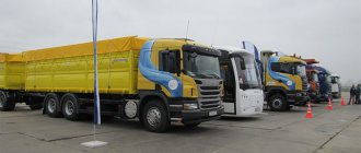
High pressure hoses (HHP), repair kits (RTI) for truck cranes and other special equipment
For questions about ordering products, please contact the sales department by phone:
(4932) 33-59-25, 33-60-39
or send a request to our email address
Depending on the volume of the order, discounts are provided
Having our own production base, we are ready to offer you the entire list of hoses for truck cranes and other special equipment. The production of hoses is carried out by qualified specialists using Uniflex equipment (Germany) from high-quality rubber pr-tv:
- Manuli (Italy);
- IMM (Italy);
- Teknohose (Italy);
- Semperit (Austria).
And also from domestically produced rubber.
In addition, we are ready to offer you repair kits (RTI) for any hydraulics of domestic truck cranes, including hydraulic cylinders. All kits come fully equipped with fluoroplastic, protective rings and guide tapes.
A large warehouse allows you to fulfill any order in the shortest possible time and ship transport, LLC "Business Lines", LLC "ZhelDorExpedition". All hoses of Gidroimpuls LLC have special marking, which guarantees 100% quality control. 1 year warranty.
| No. | Name | Cat. number | price, rub. |
| KS-3574, KS-3577 “Truck crane” | |||
| 1 | Boom lift Ts-51.000 | At Hz 200/160 production Truck crane | 760 |
| 2 | Boom extension U31.03.000 | At Hz 100/80 production Truck crane | 760 |
| 3 | Boom extension U31.08.000-01 | At Hz 100/80 production Truck crane | 580 |
| 4 | Supports Ts-22A | At Hz 100/80 production Truck crane | 475 |
| 5 | Extension of supports | At Hz 63/40, produced by Truck crane | 450 |
| 6 | 2-way valve + emergency valve | Emergency valve made by Truck crane | 360 |
| 7 | Hydraulic distributor U.063.00.000 | For hydraulic distributor produced by Truck crane | 550 |
| 8 | Hydraulic distributor of supports U3.19.00.000 | For hydraulic distributor produced by Truck crane | 500 |
| 9 | Hydraulic support distributor PX-346 | For hydraulic distributor produced by Truck crane | 760 |
| 10 | Complete repair kits for all hydraulic components of the truck crane. | For hydraulic equipment produced by Truck crane | 9 600 |
| 11 | A complete set of hoses for a truck crane | 6 800 | |
| KS-35714, KS-35715 “Truck crane” | |||
| 12 | Boom lift | At Hz 200/160 production Truck crane | 3 100 |
| 13 | Boom extension | At Hz 125/100, produced by Truck crane | 1 890 |
| 14 | Supports (hanging) | At Hz 100/80 production Truck crane | 780 |
| 15 | Extension of supports | At Hz 63/40, produced by Truck crane | 450 |
| 16 | 2-way valve + emergency valve | Emergency valve made by Truck crane | 360 |
| 17 | Hydraulic distributor U.063.00.000 | For hydraulic distributor produced by Truck crane | 550 |
| 18 | Hydraulic distributor of supports U3.19.00.000 | For hydraulic distributor produced by Truck crane | 500 |
| 19 | Hydraulic support distributor PX-346 | For hydraulic distributor produced by Truck crane | 760 |
| 20 | Complete repair kits for all hydraulic components of the truck crane. | For hydraulic equipment produced by Truck crane | 15 900 |
| 21 | A complete set of hoses for a truck crane | 6 000 | |
| KS-45717 "Truck crane" | |||
| 22 | Boom lift KS-45717.63.400-4 | At 220/160 g/c, produced by Truck crane | 3 920 |
| 23 | Boom lift KS-45717.63.400-01 | At 220/160 g/c, produced by Truck crane | 3 400 |
| 24 | Boom lift KS-45717.63.400-5 | At 220/160 g/c, produced by Truck crane | 3 950 |
| 25 | Boom lift KS-45717.63.400-5-01 | At c/c 220/160 produced by Eletshydroagregat | 4 700 |
| 26 | Boom lift (universal) | At 220/160 g/c, produced by Truck crane | 4 880 |
| 27 | Boom extension | At g/c 125/100 production Truck crane | 1 760 |
| 28 | Supports | At g/c 125/100 production Truck crane | 1 880 |
| 29 | Supports | At G/C 125/100 produced by Yeletshydroagregat | 2 250 |
| 30 | Supports | At g/c 125/100, pr-va Berezovsky RMZ | 1 390 |
| 31 | Support extensions | At g/c 63/40, produced by Truck crane | 450 |
| 32 | Support extensions | At gas station 63/40, produced by Yeletshydroagregat | 1 100 |
| 33 | 2-way valve + emergency valve | Emergency valve made by Truck crane | 360 |
| 34 | Hydraulic distributor U.063.00.000 | For hydraulic distributor produced by Truck crane | 550 |
| 35 | Hydraulic distributor of supports U3.19.00.000 | For hydraulic distributor produced by Truck crane | 500 |
| 36 | Hydraulic distributor of supports U3.30 (6sec) | For hydraulic distributor produced by Truck crane | 500 |
| 37 | Rotating joint | To the connection of the production Truck crane | 1 450 |
| 38 | Complete repair kits for all hydraulic components of the truck crane. | For hydraulic equipment produced by Truck crane | 22 800 |
| 39 | A complete set of hoses for a truck crane | 7 600 | |
| KS-4572A "Galichanin" | |||
| 40 | Boom lift KS-4572A.63.400 | At the gas center of "GAKZ" production | 1 350 |
| 41 | Supports | At G/C 140/110, produced by "GAKZ" | 1 035 |
| 42 | Boom extension | At G/C 100/80, produced by "GAKZ" | 1 190 |
| 43 | Support extensions | At G/C 80/56, produced by "GAKZ" | 660 |
| 44 | Rotating joint | For Rotating joint made by Galichanin (full) | 590 |
| KS-5476, KS-5576, KS-5476A, KS-5576B | |||
| 45 | Boom lift | At g/c 200/160 produced by Gazprom-Kran | 4 160 |
| 46 | Boom extension | At g/c 125/100 produced by Gazprom-Kran | 2 480 |
| 47 | Supports | At g/c 125/100 produced by Gazprom-Kran | 1 650 |
| 48 | Extension of supports | At G/C 80/56, produced by Gazprom-Kran | 580 |
| 49 | Rotating joint | For Rotating joint produced by Gazprom-Crane (full) | 2 700 |
| KS-55713, KS-55715 “Galichanin”, “Klintsy” | |||
| 50 | Boom lift | At G/C 200/160, produced by "GAKZ"/"Klintsy" | 3 880 |
| 51 | Boom lift | At Hz 220/160, produced by "GAKZ"/"Klintsy" | 3 900 |
| 52 | Supports KS-55713 | At G/C 125/100, produced by "GAKZ"/"Klintsy" | 1 350 |
| 53 | Supports KS-55715 | At G/C 125/100, produced by "GAKZ"/"Klintsy" | 1 500 |
| 54 | Extending the middle section | At G/C 125/100, produced by "GAKZ"/"Klintsy" | 1 650 |
| 55 | Upper section extensions | At G/C 100/80, produced by "GAKZ"/"Klintsy" | 1 380 |
| 56 | Support extensions | At G/C 63/40, produced by "GAKZ"/"Klintsy" | 780 |
| 57 | Rotating joint | For Rotating joint made by Galichanin (full) | 590 |
| 58 | A complete set of hoses for a truck crane | 16 100 | |
| KS-55721 "Galician" | |||
| 59 | Boom lift | At G/C 250/180, produced by "GAKZ" | 4 050 |
| 60 | Boom extensions | At G/C 140/120, produced by "GAKZ" | 1 930 |
| 61 | Supports | At G/C 140/120, produced by "GAKZ" | 2 000 |
| 62 | Extension of supports | At G/C 63/40, produced by "GAKZ" | 790 |
| 63 | Raising the counterweight | At G/C 100/80, produced by "GAKZ" | 1200 |
| 64 | Rotating joint | For Rotating joint made by Galichanin (full) | 590 |
| KS-6476 "Gazprom-Crane" | |||
| 65 | Boom lift | At g/c 200/160 produced by Gazprom-Kran | 4 160 |
| 66 | Boom extensions | At g/c 140/120 produced by Gazprom-Kran | 3 370 |
| 67 | Supports | At g/c 160/140 produced by Gazprom-Kran | 2 880 |
| 68 | Extension of supports | At G/C 80/56, produced by Gazprom-Kran | 590 |
| 69 | Rotating joint | For Rotating joint produced by Gazprom-Crane (full) | 2 700 |
| KS-6973 "Ivanovets" | |||
| 70 | Boom lift KS-6973A.63.400-1 | At c/c 250/180 produced by "Avtokran" | 4 130 |
| 71 | Boom lift KS-6973A.63.400-1-01 | At c/c 250/180 produced by "Avtokran" | 3 870 |
| 72 | Boom extensions | At g/c 160/140, produced by "Avtokran" | 1 940 |
| 73 | Supports | At g/c 160/140, produced by "Avtokran" | 2 075 |
| 74 | Extension of supports | At G/C 63/50, produced by "Avtokran" | 650 |
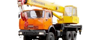
AUTO-DIESEL
| Model | Truck crane Masheka KS-4571BY-8 |
| Basic chassis | MAZ 5340V2 |
| Wheel formula | 4x2 |
| Number of sections | 4 |
| Dimensions of the crane in transport position (length/width/height), m | 10500 / 2500 / 3800 |
| Size of the support contour along x across the chassis axis, m | 6.15 (5.8) x 5.8 |
| Maximum load moment, tm | 64,0 |
| Minimum load capacity, t | 0,3 |
| Maximum load capacity, t | 20,0 |
| Gross weight, t | 18,0 |
| Engine model | YaMZ 5363 |
| Boom length, m | 8,7-26,7 |
| Reach, m: | |
| — maximum | 24,0 |
| - minimal | 3,2 |
| Maximum weight of cargo permissible for telescoping the boom, within the limits of the load characteristics, no more, t | 6,0 |
| Maximum lifting (lowering) speed, m/min | 10,0 |
| Maximum speed of lifting (lowering) an empty hook and loads up to 4 tons, m/min | 20,0 |
| Load lifting (lowering) speed, m/min (nominal / increased (loads up to 2 tons) / landing) | 7,0 / 12,0 / 0,4 |
| Maximum lifting height, m | 28,0 |
| Lifting height at maximum reach, m | 11,1 |
| Maximum lowering depth, m | 3,0 |
| Rotation speed, rpm: | |
| — maximum | 1,2 |
| - minimum | 0,4 |
| Travel speed, km/h | 60 |
| Purpose | Designed to perform loading and unloading, construction and installation work with ordinary cargo at dispersed sites. |
Load height characteristics (for three different working areas)
Load characteristics for a 280° work area (140° from the “Boom back” position in both directions)
| Reach, m | Boom length, m | ||||||
| 8,7 | 11,7 | 14,7 | 17,7 | 20,7 | 23,7 | 26,7 | |
| Load capacity of midi on outriggers, t | |||||||
| 3,2 | 20,0 | 15,0 | 12,0 | 8,5 | |||
| 4,0 | 15,8 | 14,3 | 12,0 | 8,5 | 6,0 | 5,0 | |
| 5,0 | 12,0 | 11,1 | 10,0 | 8,5 | 6,0 | 5,0 | 3,0 |
| 6,0 | 9,1 | 8,65 | 8,0 | 7,1 | 5,5 | 4,5 | 3,0 |
| 7,0 | 7,05 | 6,85 | 6,45 | 6,0 | 5,2 | 4,2 | 3,0 |
| 8,0 | 5,6 | 5,35 | 5,0 | 4,5 | 3,8 | 2,5 | |
| 9,0 | 4,6 | 4,5 | 4,2 | 3,9 | 3,2 | 2,1 | |
| 10,0 | 3,8 | 3,7 | 3,55 | 3,35 | 3,0 | 2,0 | |
| 11,0 | 3,2 | 3,1 | 2,8 | 2,8 | 1,8 | ||
| 12,0 | 2,75 | 2,6 | 2,45 | 2,4 | 1,7 | ||
| 13,0 | 2,35 | 2,2 | 2,1 | 2,0 | 1,5 | ||
| 14,0 | 1,9 | 1,9 | 1,8 | 1,4 | |||
| 15,0 | 1,65 | 1,65 | 1,5 | 1,3 | |||
| 16,0 | 1,45 | 1,45 | 1,3 | 1,2 | |||
| 17,0 | 1,25 | 1,1 | 1,1 | ||||
| 18,0 | 1,05 | 1,0 | 1,0 | ||||
| 19,0 | 0,9 | 0,9 | 0,9 | ||||
| 20,0 | 0,7 | 0,7 | |||||
| 21,0 | 0,5 | 0,5 | |||||
| 22,0 | 0,4 | 0,4 | |||||
| 23,0 | 0,3 | ||||||
| 24,0 | 0,3 | ||||||
| 25,0 | 0,3 | ||||||
| Note – Hook suspension weight 225 kg | |||||||
Load characteristics for a work area of 80° above the cabin (40° from the “Boom forward” position in both directions)
| Reach, m | Boom length, m | ||||||
| 8,7 | 11,7 | 14,7 | 17,7 | 20,7 | 23,7 | 26,7 | |
| Load capacity of midi on outriggers, t | |||||||
| 6,0 | 9,1 | 8,65 | 8,0 | 7,1 | 5,5 | 4,5 | 3,0 |
| 7,0 | 7,05 | 6,85 | 6,45 | 6,0 | 5,2 | 4,2 | 3,0 |
| 8,0 | 5,6 | 5,35 | 5,0 | 4,5 | 3,8 | 2,5 | |
| 9,0 | 4,6 | 4,5 | 4,2 | 3,9 | 3,2 | 2,1 | |
| 10,0 | 3,8 | 3,7 | 3,55 | 3,35 | 3,0 | 2,0 | |
| 12,0 | 2,75 | 2,6 | 2,45 | 2,4 | 1,7 | ||
| 13,0 | 2,35 | 2,2 | 2,1 | 2,0 | 1,5 | ||
| 14,0 | 1,9 | 1,9 | 1,8 | 1,4 | |||
| 15,0 | 1,65 | 1,65 | 1,5 | 1,3 | |||
| 16,0 | 1,45 | 1,45 | 1,3 | 1,2 | |||
| 17,0 | 1,25 | 1,1 | 1,1 | ||||
| 18,0 | 1,05 | 1,0 | 1,0 | ||||
| 19,0 | 0,9 | 0,9 | 0,9 | ||||
| 21,0 | 0,5 | 0,5 | |||||
| 22,0 | 0,4 | 0,4 | |||||
| 23,0 | 0,3 | ||||||
| 24,0 | 0,3 | ||||||
| 25,0 | 0,3 | ||||||
| Note – Hook suspension weight 225 kg | |||||||
Load characteristics for work area with outriggers fully extended to one side from 40° to 125° (85° from the “Boom forward” position in both directions)
| Reach, m | Boom length, m | ||||||
| 8,7 | 11,7 | 14,7 | 17,7 | 20,7 | 23,7 | 26,7 | |
| Load capacity of midi on outriggers, t | |||||||
| 3,2 | 15,0 | 11,2 | 9,0 | 6,3 | |||
| 4,0 | 11,8 | 10,7 | 9,0 | 6,3 | 4,5 | 3,7 | |
| 5,0 | 9,0 | 8,3 | 7,5 | 6,3 | 4,5 | 3,7 | 2,2 |
| 6,0 | 6,8 | 6,4 | 6,0 | 5,3 | 4,1 | 3,3 | 2,2 |
| 7,0 | 5,2 | 5,1 | 4,8 | 4,5 | 3,9 | 3,1 | 2,2 |
| 8,0 | 4,2 | 4,0 | 3,7 | 3,3 | 2,8 | 1,8 | |
| 9,0 | 3,4 | 3,3 | 3,1 | 2,9 | 2,4 | 1,5 | |
| 10,0 | 2,8 | 2,7 | 2,6 | 2,5 | 2,2 | 1,5 | |
| 12,0 | 2,0 | 1,9 | 1,8 | 1,8 | 1,2 | ||
| 13,0 | 1,7 | 1,6 | 1,5 | 1,5 | 1,1 | ||
| 14,0 | 1,4 | 1,4 | 1,3 | 1,0 | |||
| 15,0 | 1,2 | 1,2 | 1,1 | 0,9 | |||
| 16,0 | 1,0 | 1,0 | 0,9 | 0,9 | |||
| 17,0 | 0,9 | 0,8 | 0,8 | ||||
| 18,0 | 0,8 | 0,7 | 0,7 | ||||
| 19,0 | 0,6 | 0,6 | 0,6 | ||||
| 21,0 | 0,3 | 0,3 | |||||
| 22,0 | 0,3 | 0,3 | |||||
| 23,0 | 0,2 | ||||||
| 24,0 | 0,2 | ||||||
| 25,0 | 0,2 | ||||||
| Note – Hook suspension weight 225 kg | |||||||