Decoding error codes Thermo King SL 200
An experienced driver probably knows the most common error codes for the Termoking SL200e and other refrigerators of this brand. Those who have just started working on such a refrigerator can use a table that lists all possible errors in the Termoking SL200e and their codes. Knowing the decoding of the code, you can quickly find out the reason for the malfunction of the refrigerator and make the right decision.
The microprocessors equipped in different models of the Termoking line may differ. The table displays all possible emergency codes, and in the Termoking SL200, for example, the error codes may not contain everything that is listed in the table, just like in any other modification of the refrigerator. The table, as a rule, indicates for which units and control units it can be applied.
| 0 | No alarm messages | 85 | Forced operation of the installation |
| 1 | Microprocessor Power Reset | 86 | Discharge pressure sensor |
| 2 | Evaporator coil sensor | 87 | Suction pressure sensor |
| 3 | Return air sensor | 88 | Reserved for CR |
| 4 | Charge air control sensor | 89 | ETV Electronic Throttle Valve Circuit |
| 5 | Ambient air sensor | 90 | Electrical overload |
| 6 | Coolant temperature sensor | 91 | Entering Power Ready |
| 7 | Engine speed sensor | 92 | Sensor class not set |
| 8 | The installation operates using a coil sensor | 93 | Low compressor suction level |
| 9 | High evaporator temperature | 94 | Loader #1 |
| 10 | High discharge pressure | 95 | Loader #2 |
| 11 | The installation is controlled by an alternative sensor | 96 | Low fuel level |
| 12 | Trip due to sensor or digital input | 97 | Remote return air sensor (CR) |
| 13 | Check sensor | 98 | Fuel level sensor |
| 14 | Defrost timed out | 99 | High compression ratio compressor |
| 15 | Check glow plugs / air inlet heater | 100 | Heater fan malfunction |
| 16 | Manual start not completed | 101 | Evaporator coil outlet temperature control (CR) |
| 17 | The engine does not turn over | 102 | Low Evaporator Coil Temperature (CR) |
| 18 | High engine coolant temperature | 103 | Heater fuel level low |
| 19 | Low engine oil pressure | 104 | Check the rotation speed of the remote fan (not currently in use) |
| 20 | Engine (CR steam engine) does not start | 105 | Receiving Tank Pressure Solenoid Valve Circuit |
| 21 | Check cooling cycle | 106 | Purge valve circuit |
| 22 | Check heating cycle | 107 | Condenser Inlet Solenoid Valve Circuit |
| 23 | Cooling cycle malfunction | 108 | Opening time limit exceeded |
| 24 | Heat cycle fault | 109 | High discharge pressure |
| 25 | Check generator | 110 | Suction Line Solenoid Valve Circuit |
| 26 | Check cooling performance | 111 | Installation configuration |
| 27 | High speed steam engine | 112 | Check remote fans |
| 28 | Aborting a pre-trip test or self-test | 113 | Electric heating circuit |
| 29 | Defrost damper circuit | 114 | Multiple alarms - operation impossible |
| 30 | Defrost damper stuck closed | 115 | High pressure cut-out relay |
| 31 | Oil pressure switch | 116 | High pressure cut-in relay (currently not used) |
| 32 | Low cooling performance | 117 | Automatic switching from diesel to electric drive |
| 33 | Check engine speed | 118 | Automatic switching from electric to diesel drive |
| 34 | Modulation circuit | 119 | Reserved for CR |
| 35 | Operating relay circuit | 120 | Generator excitation circuit |
| 36 | Electric motor does not rotate | 121 | Liquid injection circuit |
| 37 | Engine coolant level | 122 | Diesel/Electric Drive Relay Circuit |
| 38 | Phase rotation error | 123 | Evaporator coil inlet temperature sensor |
| 39 | Water valve circuit | 124 | Check the temperature sensor at the outlet of the evaporator coil |
| 40 | High speed chain | 125 | Tank level sensor |
| 41 | Check engine coolant temperature | 126 | Back pressure regulator |
| 42 | Forced operation of the unit at low speed | 127 | Setpoint not set |
| 43 | Forced operation of the unit with modulation at low speed | 128 | Engine Hours Maintenance Reminder #1 |
| 44 | Check the fuel system | 129 | Engine Hours Maintenance Reminder #2 |
| 45 | Hot Gas Bypass Valve or Hot Gas Bypass Valve Circuit | 130 | Reminder No. 1 regarding motor operating hours maintenance |
| 46 | Check air flow | 131 | Reminder No. 2 regarding motor operating hours maintenance |
| 47 | Trip due to remote sensor | 132 | Maintenance Reminder No. 1 based on total operating hours of the unit |
| 48 | Check belts or clutch | 133 | Maintenance Reminder No. 2 based on total operating hours of the unit |
| 49 | Checking backup sensor 1 | 134 | Power on time |
| 50 | Reset clock | 135 | Reserved digital inputs |
| 51 | Emergency shutdown circuit | 136 | Redundant digital outputs |
| 52 | Heating circuit | 137 | Check damper motor heater output |
| 53 | Economizer valve circuit | 138 | Data logger (DAS) actual time clock battery failure |
| 54 | Test mode timeout | 139 | Interrupting the vacuum mode |
| 55 | Check engine speed | 140 | Currently not in use |
| 56 | Evaporator Fan Low Speed Circuit | 141 | Automatic switching from diesel to electric drive is disabled |
| 57 | Evaporator Fan High Speed Circuit | 142 | Check Thermax valve |
| 58 | Condenser Fan Low Speed Circuit | 143 | Check remote area drain hose heater terminal |
| 59 | Condenser Fan High Speed Circuit | 144 | Loss of CAN communication in expansion mode |
| 60 | Booster chain | 145 | Loss of controller enable feedback signal |
| 61 | Checking Low Battery Voltage | 146 | Software version mismatch |
| 62 | Ammeter out of calibration range | 147 | Fan speed output control Multi Temp |
| 63 | The engine or steam motor has stopped - cause unknown | 148 | Automatic switching from electric to diesel drive disabled |
| 64 | Pre-trip reminder | 149 | Alarm not defined |
| 65 | Abnormal temperature difference | 150 | Sensor reading below range (DAS and HMI) |
| 66 | Low engine oil level | 151 | Sensor reading over range (DAS and HMI) |
| 67 | Liquid Line Solenoid Valve | 152 | Faulty DAS sensor |
| 68 | Internal controller fault | 153 | Error loading expansion module flash |
| 69 | Magnetization reversal circuit | 154 | Trip relay malfunction due to low suction pressure |
| 70 | Hours counter failure | 155 | Lost CAN communication with HMI |
| 71 | Interservice time counter 4 has exceeded the specified time limit | 156 | Heat exchanger suction/liquid bypass valve |
| 72 | Interservice time counter 5 will exceed the specified time limit | 157 | OptiSet Plus profile mismatch |
| 73 | Interservice time counter 6 will exceed the specified time limit | 158 | Failed to load main software |
| 74 | Resetting the controller to default settings | 159 | Check the condition of the battery |
| 75 | RAM controller malfunction | 160 | Loss of communication via the CAN bus with the radio expansion board |
| 76 | Controller EEPROM malfunction | 161 | Data logger actual time clock (DAS) faulty |
| 77 | Invalid controller EEPROM checksum | 188 | Data Logger (DAS) microprocessor failure |
| 78 | EEPROM data logging failure | 203 | Return air sensor display |
| 79 | Data logger memory full | 204 | Charge air sensor display |
| 80 | Compressor temperature sensor | 216 | Data Logger Digital Inputs (DAJ) |
| 81 | High compressor temperature | 234 | Check relative humidity sensor |
| 82 | Compressor high temperature shutdown | 250 | Resetting the Data Logger (DAS) Clock |
| 83 | Low coolant temperature | 251 | Check radio expansion board configuration |
| 84 | Restart in zero mode | 252 | Check the automatic fresh air exchange circuit |
What to do if Termoking SL200e gives an error
It is better for novice drivers to have a table with them where error codes for Thermo King SL200 or other modifications are given not only with an explanation, but also with brief instructions on what to do in each individual case.
Errors of the Termoking SL200e, like other refrigerators, can be divided into several categories of complexity:
- Errors that are resolved automatically. When the controller issues such an error, the driver does not need to take any action. But the error must be recorded and reported to the technician who performs maintenance of the unit.
- Errors of Termoking SL200, etc., which do not lead to shutdown of the unit. If such a malfunction occurs, you can complete the delivery of the goods and then contact the service center. The driver can fix some problems himself.
- When the Termoking SL200e issues an error code, which is accompanied by the unit shutting down, repairs are required immediately. In this case, you will have to call the service department to the place where the unit is stopped. Knowing the Termoking SL200 error code, you can tell it to the service specialists so that when they go for repairs, they can take the necessary spare parts with them.
Thus, error codes for Thermo King SL200 and other modifications of the unit will help you make the only right decision in any situation.
Spare parts from Refkomplekt - a reliable solution to any problem with the Thermo King unit
"Refkomplekt" is a company in Nizhny Novgorod that supplies spare parts for refrigerators throughout Russia. Using the company catalog, you can purchase spare parts to solve problems reported:
- error codes Termoking SL200;
- error codes Termoking SL400;
- error codes Termoking SL300;
- Thermoking SMX 2 errors, etc.
The company's product range includes a wide selection of spare parts, from mounting bolts to fuel intake, temperature recorder and much more. etc. A wide selection of spare parts allows you to purchase all the necessary equipment in one place, and even get a good discount. Therefore, cooperation with can be beneficial both for refrigerator owners and service centers working to eliminate refrigeration errors.
Publication date: 07/24/2020
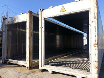
Frame
Refrigerated container bodies come in different sizes: 10 feet, 20 feet, 40 feet and 45 feet. You can read about the features of these sizes in our article Dimensions and dimensions of a refrigerated container
It is important to understand that the structure of the hull can vary greatly, based on the dimensions of the refrigerated container, manufacturer and year of manufacture.
What is the body made of?
For example, let's take the most popular size - 40 feet. The container body consists of a supporting frame (vertical and horizontal corner beams) at the corners of which there are fittings (eyelets for loading and unloading the container) and transverse floor beams.
Walls
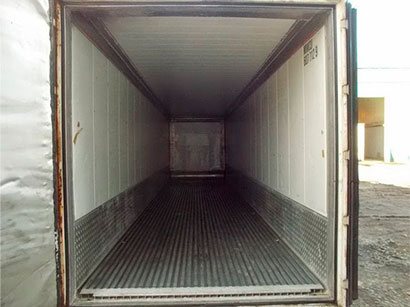
The wall of a refrigerated container is a sandwich made of polyurethane foam panels (100 mm thick) with an outer covering of stainless steel 2-3 mm thick (since 2000) or “riveted” aluminum (before 2000). The internal coating also consists of stainless steel (shiny walls) or aluminum (white walls), 1 mm thick.
Internal borders. They are also called reinforced sides. In some buildings, refrigerated containers were made to order from the shipping line. They are designed to avoid “swelling” of the housing walls. This occurs when a loaded reefer container is placed on the ground. As a result of the pressure of the load, the body inflates. If you use the refrigerator as a stationary refrigerator and do not move it loaded, then you will not see any special advantages of this modification.
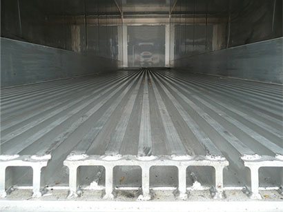
A metal sheet 0.6 cm thick is installed on the cross beams of the supporting frame. Next comes 10 cm thick foam. 3 cm plywood. And a durable T-shaped aluminum profile that can easily withstand a regularly operating loader with goods.
In a 45ft refrigerated container the floor is flat.
Ceiling
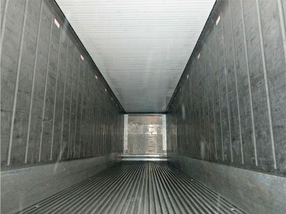
The ceiling is the same sandwich, 15 cm thick. 35-grade foam is used. The inner surface is aluminum (white color) or stainless steel (shiny ceiling). The outside is made of stainless steel.
Doors
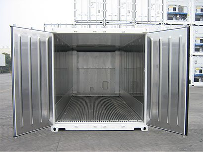
The doors are made of the same multi-layer panels as the walls and ceiling of the building. The doors swing open to an angle of 270°, which ensures convenient loading and unloading of products. The thickness of the sandwich is 10 cm. 50th foam is used. The inner side is made of stainless steel. The outer side is often made of aluminum. Less commonly made of stainless steel. There is rubber sealing at the end of the doors. Also, the doors are equipped with special latches that allow the cargo compartment of the refrigerator to be hermetically sealed.
Operating principle of a refrigerated container
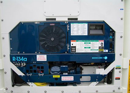
The refrigerated container system is closed and sealed. It contains freon, a cooling gas. In this case, R-134a.
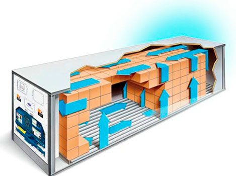
Through the suction line, this gas enters the compressor. The compressor pumps this gas and then it enters the condenser, where it is brought to a boil and becomes colder. From the condenser the gas enters the receiver. The receiver plays the role of an expansion tank. This is where the excess pressure is released. Next, the gas passes through the dryer filter, i.e. the gas is dried and supplied through the expansion valve to the evaporator. Next, the evaporator fans take the cold away from the evaporator, blowing cold air from top to bottom. The air passes through the container, circulates, returns back to the top and, thus, becomes colder with each circle. Due to this, the temperature decreases.
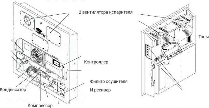
Refrigeration unit
The refrigeration unit of a refrigerated container is a “cassette” block in which electronics and components are installed.
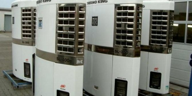
The composition and characteristics of electronics can vary greatly depending on the brand of the container (Carrier Transcold, Daikin, ThermoKing, Sabroe, Seacold, Mitsubishi). If you want to understand their differences in detail, read the article https://ref-konteyner.ru/blog/kakie-byvayut-brendy-refkonteinerov
The most popular brands are Carrier and Thermo King.
Despite the fact that there are differences between manufacturers, they are also very significant between the models of these brands. We described all the details in this article https://ref-konteyner.ru/blog/modelnyi-ryad-refkonteinerov-carrier
In the future, in this article, we will provide information using the example of the Carrier brand and the most popular model in the world, ThinLine, which has been consistently produced for more than 30 years.
The main elements of a refrigerated container installation:
- Compressor
- Capacitor
- Condenser fan
- Evaporator
- 2 evaporator fans
- Controller with multiple starters
- Receiver
- Drier filter