Technological process[ | ]
Firewood, coal briquettes, peat, etc. can be used as fuel. The operating principle of the gas generator is based on incomplete combustion of carbon. During combustion, carbon can add one oxygen atom or two, forming monoxide (carbon monoxide) and dioxide (carbon dioxide), respectively. Incomplete combustion of carbon releases almost a third of the energy of complete combustion. Thus, the resulting gas has a much lower calorific value than the original solid fuel. In addition, in a gas generator, during the gasification of wood, as well as during the gasification of coal with the addition of water (usually in the form of steam), an endothermic reaction occurs between the resulting carbon monoxide and water with the formation of hydrogen and carbon dioxide. This reaction reduces the temperature of the resulting gas and increases the efficiency of the process to 75-80%. If there is no need to cool the gas before use, then the efficiency of gasification will be 100% [ source not specified 1099 days
]. That is, in fact, two-stage complete combustion of solid fuel will be carried out.
The caloric content of the resulting gas is quite low due to its dilution with nitrogen. But since its combustion requires significantly less air than the combustion of hydrocarbons, the calorie content of the working mixture (gas + air) is only slightly lower than that of traditional air-fuel mixtures. The main reason for reducing the power of transport engines used to operate on gas without modification is the reduction in the charge of the working mixture, since it is difficult to achieve satisfactory gas cooling on mobile equipment. But this problem is not significant for stationary engines, where the mass and dimensions of the cooler are little limited. On engines specially modified or specially designed to run on generator gas, by increasing the compression ratio and slightly supercharging the gas generator, liter power equal to that of gasoline engines is achieved.
A gas generator is usually used when there are already existing internal combustion engines (both gasoline and diesel) and there is no main liquid fuel (gasoline, diesel fuel) for them.
[Section: Gas-generating cars / Date: 19.5.12 20:42]
In the TsNIIAT-AG-2 gas generator, only 51.4% of the fuel ash flows into the slag, while in the NAMI-G-76 gas generator it is 71.1%. This is explained by the more intense cooling of the gasification chamber of the TsNIIAT-AG-2 gas generator, which is surrounded by a jacket for evaporating water.
As follows, the design features of gas generating plants significantly influence the frequency of their cleaning.
Depending on the design of the gas generating unit and the properties of the consumed fuel (its strength, ash content, etc.), as well as the operating criterion, the frequency of cleaning of individual units varies within fairly wide limits.
In table 46 shows approximate cleaning times for individual parts of gas generator installations of modern gas generator vehicles.
In table 47 indicates the maintenance periods for gas generator units for working on wood chocks of ZIS-21A and UralZIS-352 vehicles, depending on road conditions (according to tests in the Zagorsk timber industry enterprise), and in table. 48 shows data on the amount of deposits in the ash pan and coarse cleaner of these installations during the period between cleanings.
When checking the reduction zone in the gas generator of a ZIS-21A car, if necessary, fill the space around the gasification chamber to the level of the neck with the freshest coal.
In the gas generator of the UralZIS-352 car, when checking the reduction zone, it is necessary to remove accumulated excess charcoal in such a way that the layer of remaining coal in the space between the grate and the lower part of the gasification chamber overlaps the latter by 20-30 mm. Removal of excess coal is done by rocking the grate.
When cleaning the ash pan of the gas generator of a ZIS-21A car, you need to ensure that when you rake out coal and focal residues, the coal hangs in the neck. In this case, if the uncharred fuel falls below the tuyere belt, then the next time the gas generator operates, the gas will contain an increased amount of tar. After cleaning the ash pan, the reduction zone in and around the gasifier chamber should be filled with charcoal.
Cleaning the ash pan of the gas generator of the UralZIS-352 car comes down to removing focal residues and takes 4-5 minutes.
When completely recharging the gas generators of ZIS-21A and UralZIS-352 vehicles, you need to disassemble them, carefully inspect them and remove deposits; If there is damage to the bunker or chamber, appropriate repairs must be made.
Cleaning the cyclone of the UralZIS-352 car is done by removing the dust collector and removing dust from it. In addition, you need to remove dust from the internal surfaces of the cyclone by tapping the cyclone casing with light blows of a hammer.
After installing the dust collector, you must tighten it tightly with the nut. The cyclone cleaning operation takes 4-5 minutes.
When cleaning the rough cleaner-coolers of a ZIS-21 A car, you need to open the hatches, pull out the sections of perforated plates, clean them with a brush, and then wash them with water from a hose. The body of each cleaner must be cleaned with a scraper and also washed with water from a hose. After cleaning, the sections of perforated plates must be replaced and the cleaners closed with covers, tightly tightening the pressure bolts of the cover fastening brackets.
When cleaning the UralZIS-352 car cooler, you should remove three adapter covers and disconnect the gas supply and exhaust pipes to remove dust from the cone adapters; The cooler pipes must be cleaned with a special scraper, after which the pipes must be washed with water from a hose. The cooler cleaning operation takes 20-30 minutes.
When cleaning the filter of the gas generator units of the ZIS-21 A and UralZIS-352 vehicles, you need to open the hatches, remove the iron rings from the filter and wash them with water from a hose in a baking tray with holes in the bottom. After 2000-3000 km of the car, the rings of the 1st section (lower) are washed, after 6000-8000 km - the rings of the 1st and 2nd sections.
Before loading the rings into the housing, the filter must also be washed with water and the condensate drain hole cleaned.
After assembling the filter, it is recommended to fill it with water through the top hatch to the level of the drain hole. The filter cleaning operation takes 30-40 minutes.
After 8,000-10,000 km, you need to completely disassemble the gas generator unit, remove all gas pipelines and the mixer and clean them of tar and dust deposits. If there are large deposits, it is best to burn gas pipelines, and the mixer should be disassembled and washed in turpentine or acetone. Cleaned parts should be inspected and repaired as necessary.
The ignition fan should also be disassembled, tar and dust should be removed from it, and the motor armature commutator should be cleaned.
After assembly, the gas generator installation must be checked for density using one of the methods indicated above.
The blower of the gas generator installation of the Ural-ZIS-352 vehicle requires painstaking care.
Bearings should be lubricated once a day by pouring oil through the top hole until it flows through the bottom hole, which is closed with a plug. The lubricant needs to be changed after 10,000 km of vehicle mileage.
It is necessary to monitor the coincidence of the pulley grooves (permissible deviation less than 0.5 mm), the correct belt tension and the cleanliness of the working surfaces of the pulleys and belt. From time to time it is necessary to clean the blower safety net from dirt.
During operation, the pipe from the blower to the gas generator often becomes tarred, so every 5000 km it must be removed and burned.
FEATURES OF WINTER OPERATION
The operation of gas-generating vehicles and their care in winter at low ambient temperatures has certain features.
These features are associated with difficulties that arise when starting the engines of gas-generating vehicles and the possibility of condensate freezing in the units of the gas cleaning and cooling system.
At the same time, experience in operating gas-generating vehicles at low temperatures indicates that an increase in heat loss from a gas-generating unit has virtually no effect on the dynamic properties of the vehicle, fuel consumption and ignition time of the gas generator. This is explained by the fact that at negative temperatures the gas enters the engine drier, and the gas-air mixture has a huge density. Because of this, the calorific value of the working charge increases and the motor power increases.
The main difficulties that arise when starting the engine in winter are associated with significant cooling of the engine and cooling of the batteries. With all this, it becomes difficult to turn the engine crankshaft due to greater resistance in the rubbing parts and a decrease in the actual capacity of the batteries.
Warming up the engines before starting with hot water or steam greatly simplifies starting and reduces the total time spent on igniting the gas generator, warming up and starting the engine to 20-35 minutes.
To increase the service life and increase the efficiency of batteries, they need to be insulated in winter. There is a linear relationship between the gas temperature tg supplied to the mixer and the ambient air temperature tb.
According to the experiments of engineer. M. Melamed for the ZIS-21 gas generator unit, this dependence can be expressed by the following equation:
Small cracks that appear can be eliminated by welding. To do this, you need to remove the aluminized layer in advance by cutting off the edges of the crack with a chisel until you get a groove 6-8 mm deep, with a wall angle of 60-70°. The welding seam must be tight, without pores or cavities.
If there are huge cracks or significant burnouts in the chamber skirt, the solid-cast gasification chamber can be repaired using one of the following 3 methods.
The first method, proposed by engineers A. S. Balabanov and A. A. Sokolov (NATI), is that the warped skirt of the gasification chamber is cut off at the level of the neck (Fig. 152) and a support cone 1 is installed under the cut chamber, which 2 is attached to the bottom of the gas generator housing with 3 legs. For this purpose, three holes are drilled in the bottom, into which fixing pins 3 are inserted and welded.
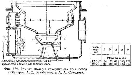
For ease of installation and dismantling of the retaining cone, the conventional ash hatch is replaced with a threaded hatch 4 of larger diameter.
When the gas generator is operating, gas passes into the gap between the cut of the chamber and the retaining cone, and ash and fine coal fall down through the hole in the cone as a result of shaking when the car moves.
The possibility of saturated sifting of focal residues into a free ash pit makes it possible to gasify in a gas generator repaired in this way not only wood lumps, but also lump peat or peat briquettes.
The disadvantages of this repair method include a decrease in the volume of the recovery zone of the gas generator. This causes an increased tendency to saturate the gas with resin and the least stable operation in alternating mode, but within limits that ensure sufficient performance of the gas generator.
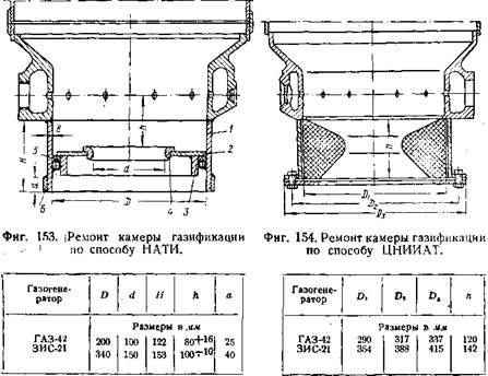
In the second repair method, recommended by NATI, the lower part of the chamber is cut to the level of the tuyere belt, to which a cylindrical shell 1 (Fig. 153) of the appropriate height, made of sheet steel 8 mm wide, is welded.
To prevent the gas from becoming saturated with resin, a metal disk 2 with a guide ring 3 is mounted inside the shell. A concentric hole in the middle of the disk, the edges of which are reinforced with insert 4, serves as the neck of the chamber.
The required connection density between the disk and the support ring is ensured by installing a gasket 5 made of corded asbestos. A ring 6 is screwed into the lower part of the chamber from its outer side, which serves to increase the service life of the chamber shell.
A similar method of repairing a gasification chamber provides it with sufficient durability.
The 3rd repair method, developed by the Central Scientific Research Institute of Automobile Transport, consists of the following: the gasification chamber of the gas generator, as in the previous case, is cut along the tuyere belt, to which a cylindrical shell is welded - a casing made of sheet steel with a width of 3 mm (Fig. 154).
A fire-resistant asbestos-cement insert (neck) is mounted inside this casing. The composition of the insert (by weight) is as follows: asbestos (dissolved) 20%, aluminous cement 80%.
When repairing single chambers, asbestos-cement necks can be made in wood form. When producing necks on a serial scale, it is advisable to use a cast iron mold.
The molded neck is covered with damp rags and left for two days, after which it is dried in air for four to five days. A chamber repaired using this method lasts more than 8,000-10,000 km, after which the collapsed neck can be replaced again with a new one.
The advantages of this repair method are low metal consumption and improved starting properties and the gasification process due to the low thermal conductivity of the asbestos-cement neck, which helps retain heat and increase the temperature in the chamber.
As noted above, the indicated repair methods are applicable only to chambers with intact tuyere belts. If cracks have formed in the tuyere belt, then it is not advisable to repair such a chamber. In this case, the camera can be replaced with the latest, lightweight type, designed by NATI or the Central Research Institute of Auto Transport.
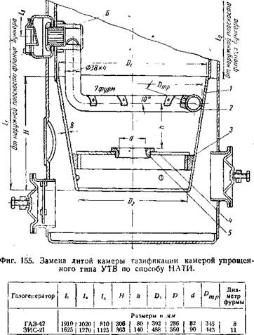
The lightweight NATI chamber of the UTV type (Fig. 155) consists of a conical shell 1, welded from sheet steel 8 mm wide, a disk 4 with a neck 5 and a guide ring 3, and an air supply pipe 2 welded to the socket of the fitting 6.
When installing the UTV camera into the gas generator of a ZIS-21 car, the height of the hopper is shortened to 1270 mm. counting from the top plane of the flange. In this case, the air valve box located in the housing is cut out and welded accordingly higher. The hole formed in the gas generator housing is sealed by applying and welding a patch.
The most wearable parts of the UTV chamber are the air supply pipe and the disk with the neck, the service life of which is 7000-8000 km.
The lightweight gasification chamber designed by the Central Research Institute of Automobile Transport is a design that combines the method of repairing chambers using an asbestos-cement neck with replacing the tuyere belt with an air supply pipe of the UTV type (Fig. 156). In this case, when removing the warped cast chamber, its upper cone is retained, to which a cylindrical casing 1 6 mm wide, equipped with a flange 2 and a stubborn ring 6, is welded.
In the upper part of the casing, at the level of the axis of the air valve box, a hole is made for welding the socket of the air supply pipe 5. The asbestos-cement neck 4 is inserted into the casing until it stops in the ring 6 and then secured with the help of a support ring 3, which is bolted to the flange 2.
Repair of bunker and housing
As already indicated, the gas generator bunker in its upper part is destroyed under the action of acids contained in dry distillation products.
A ring patch 50-200 mm high, made of 1.5 or 2 mm sheet iron, should be welded onto the warped upper part of the hopper from the outside.
By applying patches, a burnt-out gas generator housing is also repaired. If there are dents on it, they are corrected by straightening with a hammer, striking from inside the body. Increased attention should be paid to straightening damaged shells and ash pan covers.
To ensure a tight fit of the lid to the shell of the hatch, the latter, after straightening, is sawed off with ratfil.
The repaired hopper and gas generator housing must be tested for density before assembly.
Cleaner repair
Coarse cleaners, as well as the gas generator hopper, are gradually destroyed due to corrosion.
Those sections of the coarse cleaner in which condensation occurs are more susceptible to corrosion.
In the gas generator installation of the ZIS-21A car, the perforated plates of the third section of the coarse cleaner are first destroyed.
In this case, the destroyed plates are replaced with others taken from sections previous along the gas path. The first section of the purifier can operate without plates, capturing dust due to a drop in the gas flow rate.
If the perforated plates of all sections are destroyed, they must be replaced with new ones.
Making perforated plates is a very labor-intensive process, so they can be made without holes. The plates must be cut by 1/3 of the diameter (or width) alternately on the right and then on the left side. When they are used, the path along which the gas moves in the purifier becomes tortuous.
Destroyed plates can also be changed with wood wool (packing shavings), which is placed in the housings of the coarse cleaner sections. The filling with shavings should not be dense.
Corrosion holes discovered during the repair of purifier housings must be sealed by welding external patches.
The body of the narrow gas purification filter is relatively slowly corroded by condensate acids and therefore lasts quite a long time. The holes in most cases are formed in the bottom of the housing; they are sealed with patches.
The iron rings in the filter are subject to severe destruction.
In the absence of spare rings, you can put wood wool in the filter, which still needs to be changed every 2000-3000 km, which is a drawback of its implementation.
The gratings supporting the layer of rings, in case of destruction, can be made again from sheet iron 1-2 mm wide. Holes with a diameter of 10 mm are drilled into them at a distance of 13-15 mm from one another. To give the grille the required rigidity, it is welded to a metal ring made from a rod with a diameter of 12-15 mm.
ECONOMICAL OPERATION OF GAS VEHICLES
The need to introduce gas-generating vehicles is determined first by the need to properly use the fuel resources available in the country. At the same time, the efficiency of gas-generating vehicles is of no small importance.
In a number of places, gas generator cars are designed to replace cars running on watery fuel, so it is important to compare the operating efficiency of gas generator cars with the efficiency of gasoline cars.
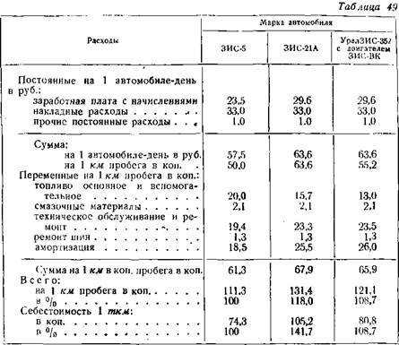
In table 49 shows data on individual items of fixed and variable expenses and on the cost of operating a ZIS-5 gasoline car with a carrying capacity of 3 tons and gas-generating ZIS-21A cars running on wood lumps with a carrying capacity of 2.5 tons and UralZIS-352 cars, the carrying capacity of which is conventionally assumed to be 3 tons (with high-power ZIS-VK engine).
The basis for calculating the cost of operating these vehicles is based on the following initial data.
1. Drivers’ salaries are calculated based on the basic salary of 520 rubles. (for group III roads), to which is added a 15% increase for class II and a 30% increase to the basic salary for the driver of a gas-generating vehicle in accordance with the current regulations; The amount of accruals is taken to be 4.8% of the salary fund.
2. The price of gasoline is assumed to be 640 rubles. for 1 t plus 64 rub. for leading.
The price of wood chocks is 140 rubles. for 1 t.
The price of charcoal corresponding in quality to that used for the restoration zone is 180 rubles. for 1 t.
3. The price of lubricants, maintenance and operational repairs of vehicles, as well as tire repairs are taken according to the standards approved by the Ministry of Auto Transport and Highways of the USSR for 1954.
4. Depreciation deductions for paying off the price of cars, carrying out long-term repairs and restoring tires were adopted in accordance with Order No. 5 of January 10, 1952 of the former Ministry of Auto Transport of the RSFSR.
5. The daily mileage of the ZIS-5 vehicle is assumed to be 115 km, and the gas generator vehicle ZIS-21A is 100 km in accordance with the lower average technical speed of its movement.
For the UralZIS-352 gas generator vehicle with the high-power ZIS-VK engine, the daily mileage is assumed to be equal to the daily mileage of a ZIS-5 gasoline car.
6. For all 3 types of cars, the tonnage utilization factor is assumed to be 1, and the mileage utilization factor is 0.5.
As can be seen from table. 49, the cost of 1 km of run of a gas-generating car ZIS-21A is 18% higher than that of a gasoline car ZIS-5, despite the fact that the price of a combustible gas-generating car per 100 km of run is 21.5% lower than the price of gasoline.
The indicated increase in the cost of running the ZIS-21A gas generator vehicle is the result of inflated costs for wages (by 26%), technical service, operational repairs (by 20%) and depreciation charges (by 38% due to the higher initial price of the car and the huge costs of full repair).
In addition, the reduced average technical speed of a gas-generating vehicle causes an increase of 15% in fixed costs per 1 km of run.
A more significant impact on the increase in the cost of transportation by a gas-generating vehicle is caused by a decrease in the carrying capacity from 3 to 2.5 tons compared to a ZIS-5 gasoline vehicle. As a result, the cost of 1 tkm additionally increases by approximately 24% and in total amounts to 141.7% in relation to the price of transportation using gasoline.
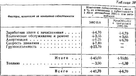
In table Figure 50 shows the relative impact of all of the above reasons on the increase in the cost of transportation by gas-generating vehicles.
The table shows that a decrease in the productivity of the ZIS-21A gas-generating vehicle (travel speed and load capacity) has an approximately 2-fold greater impact on changes in transportation costs than all other reasons taken together. As follows, one of the main methods of reducing the cost of transportation by gas-generating vehicles is to increase the power of their engines and increase the load capacity at least to the values of these values for the ZIS-5 vehicle.
In table 50 data on the cost of transportation for the UralZIS-352 vehicle are given provided that it is equipped with an overpowered ZIS-VK engine and the load capacity is increased to 3 tons.
With all this, it is also taken into account that the UralZIS-352 gas generator vehicle does not necessarily require auxiliary fuel (charcoal and starting gasoline), but has somewhat inflated costs for repairs and depreciation due to a certain complication of the engine design.
As can be seen from table. 49 and 50, the cost of 1 tkm for the UralZIS-352 car is only 8.7% higher than for the ZIS-5 gasoline car.
The upcoming reduction in the cost of transportation due to an increase in the carrying capacity of gas-generating vehicles is more targeted by introducing semi-trailers with a flatbed body or single-axle trailers for transporting long cargo.
The use of a gas-generating vehicle-tractor also allows for a better placement of the gas-generating unit on the chassis, without resorting in this case to reducing the size of the cabin to preserve the usable area of the body.
The above calculations of the cost of operating gas-generating vehicles are based on the use of wood lumps as gas-generating fuel. The cost of delivering gasoline to remote areas of the country, where the use of gas-generating vehicles is more targeted, is not taken into account in these calculations.
As can be seen from the data given in table. 51 for gas generator vehicles running on charcoal, brown coal or anthracite, the operating cost should be at. other equal criteria is lower than when working on wood chocks. So, for example, when working on anthracite, the cost of 1 tkm will additionally decrease by 6.3% compared to working on wood chocks.
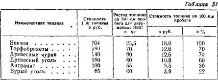
But it must be borne in mind that the presence of harmful impurities in anthracite and brown coal (sulfur), as well as the tendency of these fuels to form saturated slag, can cause a certain increase in the cost of technical service and repair of a gas-generating vehicle compared to working on wood lumps or charcoal, which will somewhat reduce the benefits obtained from the introduction of the above fuels.
If we take into account the costs of transporting gasoline over a distance of 3000 km at existing railway tariffs in the amount of 169 rubles. for 1 ton and the cost of transporting it by road from the steel road to the destination over a distance of 100 km, taking into account the cost of transportation according to the data in Table. 50 equals 74.3 kopecks. for 1 tkm, then the price of gasoline consumed by a ZIS-5 car per 1 km of run will increase from 20 to 27 kopecks.
Under these criteria, the cost of 1 tkm for a gas-generating car, running, for example, on anthracite and having a performance similar to a gasoline car, will be only 99% of the cost of 1 tkm for a gasoline car.
The given economic calculations of the cost of operating gas-generating vehicles in comparison with gasoline vehicles did not take into account such a fundamental factor as the strategic value of petroleum fuel.
In order to more accurately assess the economic need for the introduction of gas-generating vehicles, this factor must also be taken into account.
GAS GENERATOR Auto KTN G.G.Tokarev 1955
« 1 [2]
Related posts:
- Car steering rack repair and its features
- Characteristics of canopy and canopy structures
- Where to start renovating an apartment
- Ekaterinburg
- Dental implant: what you need to know about the specifics

