What is injection timing?
On diesel cars, it is more correct to call ignition the injection moment. It represents the beginning of the fuel supply when the piston approaches top dead center (the intake and exhaust valves are closed). Maximum pressure is created in the working chamber, at which point fuel is supplied.
How to set the ignition on a KamAZ? It would seem that it is worth adjusting it once at the factory when the car is released and not worry about it. However, not all so simple. The fact is that each power unit has a specific injection moment, due to the characteristics of the engine components. In addition, this indicator is influenced by the quality and type of fuel.
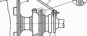
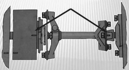
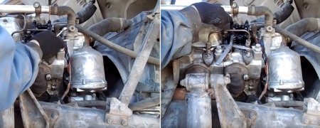
Arrangement of cylinders on KamAZ 5320

Video views: 1780279
Category: French cars
Description: Good afternoon reader, do-it-yourself car repair is a collection of all kinds of instructions (articles, videos, photo reports, questions/answers) that clearly show how to do the repair yourself. For ease of use of the etlib.ru website, all materials are divided by car brands and models, as well as into categories and types of materials. When buying a car, car enthusiasts are increasingly interested in doing their own car repairs. And so everything is in order, the length of the body of your car is 3295, width is 1626, height is 1611 mm. The wheelbase is 2763 mm. Ground clearance 146 mm. The car is equipped with a hybrid power unit. The four-cylinder engine is equipped with a system that provides engine power output. There are sixteen valves per engine. The diameter of one cylinder is 59 mm, the piston stroke is 46 mm. The engine crankshaft accelerates to 5000 rpm. Maximum torque is maintained up to 9000 rpm.
Original video title: Sylinderne KAMAZ 5320
Release date: 07/08/2020
Duration: 6:40
Quality: HD DVD
Posted by admin: at the request of Ovadyaa
Reasoning of a car owner named Lamprecht: Appearance….
Laughter on the topic: There is a shopping arcade on Privoz. Sheepskin coats for sale. A plump woman comes up and starts looking. Seller: - Buy a woman, very good sheepskin coats, different styles, different colors. Woman: - Is there one with trihuel? - For your money and with trihuel we will find it! He chooses a sheepskin coat, gives it to the woman, she tries it on, pays and leaves. Opposite the young guy sells leather jackets and listened carefully to the conversation all the time. He approaches the seller and says: “Show me a sheepskin coat with trihuel, I’ve never seen it.” The seller shows: size XXXL.
Necessary tools for work: 1. Hammer;2. Open-end wrench 28; 3. Socket wrench 13;4. drill for 6; 5. soap; 6. gearbox;
Video instruction: arrangement of cylinders on KamAZ 5320
V-engine part 2
Adjusting KAMAZ valves - New Method
repairmotors.ru
Settings
Any automotive power plant has marks (degrees) designed specifically for setting the ignition. If the system is adjusted strictly according to the marks, the engine will operate in optimal mode, provided that the injection pump, engine and fuel meet the reference characteristics according to GOST. By and large, the indicators are a kind of guideline that allows you to understand how to set the ignition on a KamAZ.
On the car in question, the high-pressure fuel pump is placed on a key on the side of the box, and the injection pump coupling can be fixed in two positions with a difference of 180 degrees. As a rule, if the drive pressure screw is located in the upper part, then the injection pump and clutch marks should be placed opposite.
Peculiarities
After all the parts are aligned to the marks, you need to tighten the fixing elements and start the engine. The car should start without problems the first time. If the truck does not start or white smoke comes out of the exhaust system, then the alignment is not done correctly by 180 degrees. You will need to unscrew the required parts and rotate them 180° and restart the engine.
If there are no marks or there are unnecessary marks, it is advisable to place the elements approximately in the middle of the adjustment marks. To understand how to correctly set the ignition on a KamAZ, it is necessary to take into account the signs of late and early injection.
Early injection point
With early ignition, the piston does not have time to reach the top point, and fuel already begins to enter the working chamber. The main signs of this moment:
- Rough motor operation.
- When you actively press the gas pedal, a characteristic ringing sound is heard, which intensifies as the temperature of the power unit rises.
- White smoke may appear from the exhaust pipe.
- There is poor traction.
- Fuel consumption increases.
Late ignition: signs
At a late injection moment, the piston moves down from top dead center, and fuel is just starting to flow, the ignition follows. Signs of a problem:
- The appearance of white smoke from the exhaust system. The later the ignition, the greater the amount of smoke observed.
- The motor does not rev up correctly.
- The operation of the power unit is observed to be too soft.
- When the gas pedal is smoothly activated, the engine begins to shake at medium speeds, and when the torque increases, this effect abruptly disappears.
- Fuel consumption increases, the engine heats up, and the truck pulls poorly.

How to set the ignition correctly on a KamAZ Euro?
The factory settings generally assume a slightly late injection timing. If it is necessary to adjust the unit towards early ignition, perform the following manipulations:
- The injection timing is set at the operating temperature of the engine.
- The drive is adjusted so that the mark is on top.
- Loosen the two fixing screws at “17”.
- You only need to rotate the injection pump coupling.
- To enhance early ignition, the drive rotates clockwise, and for late injection, counterclockwise.

Adjustments should be made literally millimeter by millimeter, with the obligatory tightening of the bolts.
Knowing how to set the ignition on a KamAZ, after setting it up, you should start the engine and check it. If the operation of the power unit does not suit the owner, manipulations with the settings are continued until a slight ringing noise appears when the gas pedal is sharply activated. After another small shift it will disappear, which will indicate that the required ignition timing has been reached. A correctly set injection point will allow you to achieve better traction and fuel economy, which is important when operating any equipment.
Adjusting valves KAMAZ 740
Timely adjustment of KAMAZ Euro 3 valves and other modifications increases the service life of the power unit and eliminates expensive repairs.
Ignoring the problem and saving in this case leads to the following consequences:
- burnout of pistons;
- loss of power;
- increased fuel consumption;
- expensive repairs.
The reason is a violation of the sealing of the intake and exhaust cylinder due to displacement of the valve tappet gaps. This is the exact value that must be set to ensure complete combustion of the air-fuel mixture and efficient removal of exhaust gases.
Adjustment of valves of KAMAZ Euro 4 and other modifications of the series is necessary if the running engine makes rattling sounds. Timely elimination of the failure will reduce damage to engine life and eliminate wear and tear on engine components and assemblies.
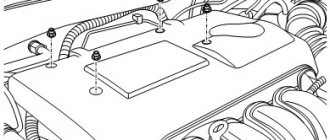
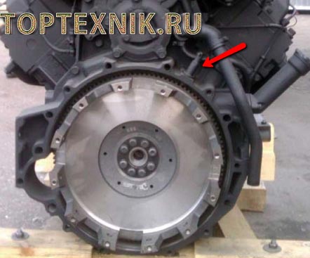
It all starts with removing the cylinder head cover and installing the crankshaft in a certain position. The operation is performed using a rod passed through the technological holes of the flywheel. When they are connected to the crankcase stopper, thanks to the action of the spring, the position of the engine cylinder necessary for precise adjustment is established. The markings on the injection pump will help here. When the flywheel has reached the desired position, the stopper is removed and the crankshaft should be turned clockwise 60 degrees or 2 flywheel holes. As a result, the first and fifth cylinders are completely closed.
The next stage is adjusting the valves of KAMAZ 740 and other modifications. The flywheel is now rotated 180 degrees, which corresponds to six holes. Here the craftsmen work with valves 2 and 4. This is followed by the same rotation and adjustment of the KAMAZ KAMNIZ valves of the sixth and third. The final stage is to rotate the flywheel another 6 holes or 180 degrees to work with cylinders 7 and 8. Working in pairs is explained by the need to set the gap on two cylinder heads.
KamAZ-740: how to set the ignition?
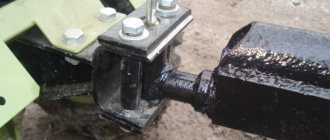
The injection timing is set simultaneously with the installation of the injection pump. The stages of work are given below:
- The cabin rises until the latch clicks into place.
- The flywheel housing rod is lifted and rotated 90 degrees and placed in a special niche on the housing.
- At the bottom, a pair of bolts are unscrewed and the dirt protection shield is dismantled.
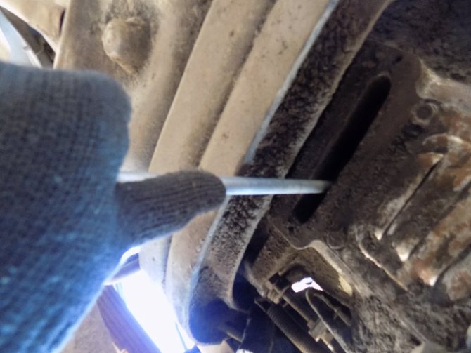
- A metal rod with a diameter of 10 and a length of about 400 mm is inserted into the flywheel hole through the slot.
- The crankshaft is turned from left to right until its movement is blocked by the lock rod.
- The position of the injection pump drive shaft located in the camber of the cylinder block is checked.
- If the fuel pump drive coupling is turned with the operating scale up, align the zero point with the mark on the pump flange, and then tighten the two mounting bolts.
- If the position of the part is the opposite, lift the stopper, turn the crankshaft one revolution, and repeat the steps indicated above.
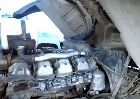
Preparing the car
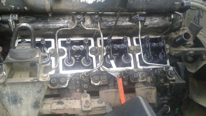
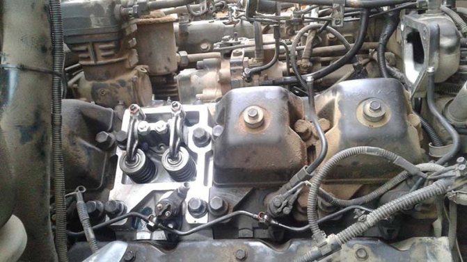
The machine being manipulated is placed on a flat surface. The driver's cabin reclines and locks. The upper part of the gas distribution mechanism is dismantled and the pump is turned off.

- Keys: open-end for 13, ring for 14;
- Screwdrivers;
- Steel rod;
- Set of measuring plates.
Fixing the main chamber piston at the top
- Check the fixation force of the camera heads;
- Move the flywheel stop device down;
- Remove the flywheel housing protection plate;
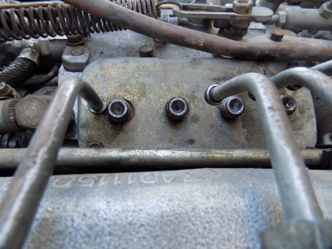
- Insert the steel rod into the hole in the flywheel, turn clockwise until the product stops. Position – beginning of mixture injection (cylinder one).
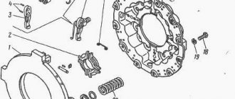
Flywheel retainer, KamAZ engine:
Setting gaps
- Rotate the flywheel (2 holes – 60°, each 30°);
- Adjust the spacing of the first pair of cameras (1st and 5th). Using a 14 ring wrench, loosen the nuts
- adjusting screws. Use the 0.3 plate to adjust the intake valve, and the 0.4 plate to adjust the exhaust valve.
- Fix the nut, force 33-41 Nm.
- Adjust the spacing in chambers one through eight.
Setting up KamAZ 740, 6520, 5511 valves and other modifications:
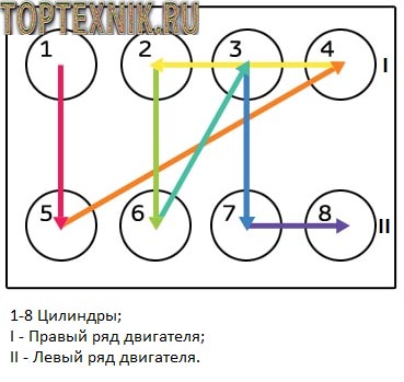
- 180 degrees – 4th, 2nd;
- 180 degrees – 6th, 3rd;
- 180 degrees – 7th, 8th.
In conclusion
Despite the fact that the diesel power unit has a simple and understandable design, the elements of its fuel system are considered high-precision devices. In this regard, the installation of a high-pressure fuel pump requires special attention and optimal determination of the angle of injection of diesel fuel through the nozzle into the working cylinder at the compression stage. Even an error of just one degree can lead to engine failure, which will require an emergency overhaul. Reliable KamAZ Euro trucks are popular in various areas. How to set the ignition on different modifications is discussed above. Knowing the features of this procedure, it is quite possible to adjust the timing of fuel injection on your own with minimal investment of time and equipment.

One of the main systems of any modern vehicle, including KAMAZ, is the ignition system (IS). With its help, the power unit is started and the engine continues to operate in optimal mode. For more information about the order of operation of the cylinders, how the KAMAZ ignition switch functions and how to adjust the ignition timing with your own hands, read this article.
Kamaz 65116 2 doors. tractor, 260 hp, 10 manual transmission, — adjustment of clearances in the valve drive
contents .. 979 980 981 ..The clearances in the engine valve drive are not adjusted
Why do you need valve adjustment?
A modern car has two valves per cylinder (or more). One of them starts the combustible mixture, and the other releases the exhaust gases (they are called intake and exhaust). And the mechanism that activates these valves and establishes the order of their operation is called gas distribution or valve. After the engine heats up, the parts expand. Consequently, on a cold engine there must be strictly defined gaps between some of its parts.
If the valves are not adjusted correctly, this can lead to a decrease in engine efficiency and a decrease in the life of its parts. For example, if the gaps are small, the valves and their seats will burn out and the overall service life of the motor will decrease. With large gaps, when the valves do not open completely, engine power will drop noticeably - you will hear a distinct metallic knock. What happens if there are small valve clearances? Small valve clearances will cause the valve seats to burn.
What happens if there are large valve clearances?
Large valve clearances will result in incomplete valve opening, which will affect engine power. Increased valve clearances can be recognized by a characteristic metallic knock. Noises in the engine may indicate a timing fault.
Data on thermal clearances can be found in the car repair manual. They are different for each motor. Note that the clearances are different for the intake and exhaust valves, and sometimes for different cylinders.
The frequency of valve adjustment, if provided for by the engine design, is indicated in the vehicle’s operating manual.
How does the adjustment take place?
In order to check and adjust the clearance, the engine must be cold. The thermal gap is checked with a flat probe of a certain thickness. The adjustment is made by turning the rocker arm adjusting screws in the required direction.
To begin adjustment, set the piston of the cylinder you are adjusting to top dead center of the compression stroke. In this position, both valves of a given cylinder are closed, and the rocker arms should swing freely within the clearance.
Then loosen the locknut on the adjusting screw or bolt. Using a feeler gauge and adjusting screw (bolt), adjust the required clearance, then tighten the locknut. Be careful: sometimes after tightening the locknut the clearance may change, so this operation must be done carefully. After tightening, check it again. The gap will become optimal when the probe passes into it, overcoming a slight force. If it goes too easily or too hard, readjust.
Then, turning the crankshaft half a turn, you need to adjust the clearance in the valves of other cylinders. Here it is necessary to observe the order of operation of the cylinders of your car's engine (for example, 1-3-4-2). The crankshaft should be turned only clockwise and only by the “crooked starter” handle (starting handle) or by the bolt securing the generator drive pulley. You can turn the crankshaft using the suspended drive wheel, but you must be careful here.
WHY VALVES DO NOT NEED TO BE ADJUSTED ON SOME MOTORS
The repeated clarification that valve adjustment must be provided for by the engine design is very important: after all, many engines do not require this procedure. This depends on whether the motor is equipped with hydraulic compensators: these are devices designed to automatically adjust the thermal gap. They operate using oil supplied to them from the engine (which is why, in fact, they are called “hydraulic compensators”) and completely eliminate the need for periodic manual adjustment of the valves. They themselves, of course, also do not last forever - the need to check and replace them is indicated by the same clicking knock, which does not disappear soon after starting, and sometimes even after the engine warms up. However, the main thing you need to know in the context of this material is that engines equipped with hydraulic compensators do not need valve adjustment.
If the vehicle engine does not have hydraulic compensators, then the valves must be adjusted manually. It’s quite easy to know that it’s time to do this by looking at some of the symptoms. One of them is the characteristic “clicking” of the valves, which was already mentioned above, and the other is that the engine begins to “trouble,” and compression in its cylinders either drops significantly or completely disappears. As soon as at least one of these symptoms appears, it is necessary to check the size of the gaps in the valve mechanism.
Specifications
Technical characteristics of KamAZ 65116 in a body of 2 doors. tractor with a 260 hp engine, 10 manual transmission produced in
Basic data
- Start of production:
unknown - End of production:
in production
- Body:
2 doors tractor
Engine
- Engine type: V8
- Fuel grade: diesel fuel
- Engine capacity, cubic meters see: 10850
- Supercharging: turbocharging
- Power, hp: 260
- Achieved at vol. per minute: 2200
- Maximum speed, km/h: 90
- Power system: diesel
- Cylinder diameter, mm: 120
- Piston stroke, mm: 120
- Compression ratio: 16.5
Transmission
- Transmission: Manual
- Number of steps: 10
Other
- Fuel tank volume, l: 350
contents .. 979 980 981 ..
Basic elements of SZ
The main components of such a SZ:
- Filter element.
- Additional resistor SZ.
- Capacitor filter.
- A starter unit used to generate a high-voltage pulse.
- Emergency vibrating device.
- A distribution device, popularly called a “distributor”.
- Spark plugs, one for each cylinder.
- Coil.
- Transistor switching unit.
- Ignition switch or lock KAMAZ Euro 3.
Features of the ignition switch
In order to properly adjust and configure the system’s performance on a Euro 3 KAMAZ, we recommend that you familiarize yourself with the main features of the lock’s operation. This unit is a switching device used to turn on and off the power unit, as well as the entire on-board network of the vehicle.
In KAMAZ Euro 3 or 2 vehicles, this mechanism performs the following functions:
- With its help, the machine’s bot network is activated and disconnected to the battery, as well as to the generator unit. Moreover, the network is disconnected from the battery after starting the power unit, since after this the power supply is supplied from the generator.
- Also, thanks to the lock, the SZ itself is activated and deactivated, in particular, its primary low-current motor circuit to the voltage source.
- The lock also briefly activates the starter assembly when you turn the key and try to start the power unit.
- As you know, the lock itself has several operating positions. In the initial position, all devices and systems are turned off, the on-board network is de-energized. By turning the key to position I, you can turn on the car's audio system, optics and some other mechanisms connected to the ignition when the power unit is turned off. The end position is used directly to start the engine.
- The lock can also serve as an anti-theft option, activating the steering wheel locking mechanism when the engine is turned off (the author of the video is the ICE Theory channel).
Ignition Tuning Guide
How to correctly set the ignition angle in KAMAZ vehicles? Since domestic truck engines are very sensitive to incorrect clearance adjustment, the set angle should be set as correctly as possible.
Otherwise, the power unit will not work correctly:
- First, you should set a mark on the injection pump so that fuel is injected 4 mm earlier until the piston reaches the TDC position. In practice, this can be determined by placing a mark along the edge of the indicator arrow attached to the high pressure fuel pump. In other words, you need to rotate the motor in the direction of travel until the mark is aligned with the arrow mark. At the moment of their combination, fuel is supplied to the combustion chambers.
- Further, the mark will move further. The piston will enter top dead center at the moment when this mark is aligned with the edge of the index arrow. To prevent mistakes at this stage, the position of the piston at the point described above must be secured using a special stopper, which can be seen on the flywheel housing.
- It must be taken into account that during one rotation of the high-pressure pump shaft, the piston will reach the dead center position twice. And you need to understand in what position the compression stroke occurs in cylinder 1 - in the first or second. If, when adjusting the advance angle, you do not dismantle the pump, then you can simply move the mark on its coupling to the index arrow. Next, the stopper can be lowered, after which the flywheel should be rotated in different directions, this will ensure that the stopper element fits into the groove. The flywheel itself should be rotated using a lever installed in a special hole at its end.
- By following these steps you will be able to ensure that the piston is positioned at the compression torque point. Next, you need to loosen the screws securing the pump drive and align the mark with the extreme part of the pointer. As practice shows, this position is considered the most optimal. If the mark is shifted to the side, the engine as a whole will begin to function incorrectly, its speed will fluctuate.
Adjusting valve clearances on the KamAZ-740 engine
The KamAZ-740 engine will be the main topic of this article. Guided by the data from this article, any experienced and novice driver will be able to quickly and most importantly
The KamAZ-740 engine will be the main topic of this article. Guided by the data from this article, any experienced and novice driver will be able to quickly and, most importantly, efficiently adjust the thermal valve clearances on their KamAZ vehicle. Using these skills, you can save a lot of time during repairs in the future. First you need to prepare the car and install it on an inspection ditch or on a flat area. The main thing is not to forget to set the car to the handbrake or you need to use anti-recoil devices. After this, raise the cab and lock the cab lift limiter, wait until the engine cools down. After the KamAZ-740 engine has cooled down, you must remove the valve covers, this way the rocker arms and valve stems will cool faster. There is a lever on the high pressure fuel pump - it must be set to the stop position, this will prevent the engine from accidentally starting. You should also have a crowbar or a large Phillips screwdriver, it will come in handy here. After this, the installation of the piston of the first cylinder at TDC begins. You will need to check the tightness of all cylinder head bolts. Of course, if necessary, they will need to be tightened. Then we lift the flywheel lock rod and turn it 90 degrees, then release it. Under the action of a special spring, the clamp rod will lower and then rest against the flywheel itself. If the retainer is dirty, wash the whole thing in diesel fuel. After this, go down under the car and remove the flywheel housing hatch cover. The roof has an oblong appearance and is attached with two M8 bolts. You need to take a crowbar and insert it into the hole in the flywheel and start rotating it as the engine runs, that is, it turns out clockwise, if, of course, you look at it from the front of the engine. You need to rotate this thing without jerking and until the locking rod is lowered into the groove of the flywheel. After the flywheel stops, you will need to get out from under the car and look at the driving coupling half of the pump drive; the marks on the driving coupling half, as well as on the end of the clutch housing, should be somewhere above. If there are no such marks, then they are currently located at the bottom and you still need to turn the flywheel. To do this, you need to remove the locking rod from the groove of the flywheel and turn it all one more turn. The flywheel has 12 lugs and holes, so you can count the holes by turning it. At the 12th hole you will need to release the latch and bring the 12th hole to the edge of the hatch. In any case, the clamp rod will not immediately fit into the groove of the flywheel. You will have to insert a crowbar into the thirteenth, that is, the first hole and slowly begin to rotate the flywheel, as it rotates the rod should enter the groove. After this, look at the coupling half again, if you see marks and the valve springs are pressed out, then everything has been done correctly and now you can begin adjusting the valves of the KamAZ-740 engine. Start removing the rod from the groove and turn it 90 degrees, you need to leave it in the upper position of the lock. Now you can adjust the gaps. The angle of rotation from the first hole in the flywheel to the second is thirty degrees, and in order to adjust the gaps, we need to rotate the crankshaft 60 degrees, that is, by 2 holes. Therefore, very often the driver will hear calls from the motor mechanic to rotate twice or 2 holes. While rotating, you need to count to two, and so on with each hole. Don't forget that the rotation occurs clockwise and this is when viewed from the front. Let's start adjusting the gaps on the first pair of heads. To prevent the screw from starting to rotate together with the nut, it must be held with a screwdriver. Take a regular 0.3 millimeter thick feeler gauge and insert it between the intake valve stem and the rocker arm. At this time, you need to tighten or loosen the adjusting screw. It is necessary to ensure that the feeler gauge moves between the rod and the rocker with only a slight force and does not bend. No need to remove the dipstick. Tighten the locknut and hold the adjusting screw so that it does not turn. After this, check again if the dipstick moves. To check, you can even insert a slightly thicker probe, which ideally should not pass through. After this, take a feeler gauge that is already 0.4 millimeters thick and insert it between the exhaust valve stem and the rocker arm. Perform exactly the same steps as last time, only you need to check the gap with a feeler gauge 0.45 millimeters thick. At the very end, grab the bar with your fingers and twist it, it should spin without any jamming. If it sticks, it means that it is bent and in this case it needs to be replaced or repaired. Having adjusted the gaps on the first cylinder, you can move on to the fifth and perform the same actions. After this, you will need to go under the car and turn the crankshaft exactly 180 degrees. That is, you must insert a crowbar into the hole and move it to the other edge of the hatch. This must be done 6 times on cylinders 7-8, cylinders 6-3 and cylinders 4-2. After this, check the correctness of the adjustment. It even happens that the crowbar may jump out during rotation and you need to check yourself. To do this, you need to lower the special locking rod and rotate the crankshaft 120 degrees. After this, the locking rod should fall into the groove of the flywheel and, of course, lock it. If everything happened like this, then the adjustment was successful. If not, remove the shock and check the cylinders. That's all, now you know how to adjust thermal gaps and can help your colleagues. This is especially true in car services or in cases where, on the contrary, it is impossible to get to the service and you have to do everything yourself.
Category: Articles
| 726
Similar articles
Video “How to make KAMAZ more economical?”
Recommendations and step-by-step instructions for repairing a KAMAZ in order to achieve its efficiency are shown in the video below (the author of the video is Petr Alekseevich Yurkov).
The ignition system in all vehicles is designed to ignite the fuel mass in the cylinders of internal combustion mechanisms. This part of the car must be well-debugged and must function properly in order to avoid unpleasant situations while driving. Ignition is an extremely important moment for the operation of the machine.
Ignition system
There are a number of requirements for the launch system itself that are necessary for the normal operation of the car. These include:
- creating a spark in the cylinder at a certain moment;
- ensuring a rational engine starting moment, that is, the spark should appear with optimal advance, the interval of which varies depending on the engine speed and the current load;
- a certain strength and energy of the spark, the quantitative value of the energy varies proportionally depending on the physical and chemical characteristics of the fuel mass.
Ignition can be carried out in the following ways:
- through the microprocessor of an electronic device, where electrical energy is stored. The microprocessor controls the resulting energy and creates a spark;
- contact method, where the process is controlled by a special distributor - distributor;
- in a contactless way, where what is happening is controlled by a transistor switch that interacts with contactless sensors.
The processes are different, but the design itself has many similar parts. For example, spark plugs, a battery, a switch, devices for distributing and accumulating charges, as well as a 1703 KAMAZ belt.
Settings

Injection timing and ignition are different names for the same process. Injection is the start of the supply of fuel mass when the piston moves to the maximum point. The KAMAZ EURO 2 starter must be in good working order. The intake valves must be closed, as well as the check valves. Due to this, maximum pressure appears in the functioning chamber. At the same time, fuel is supplied.
Of course, diesel cars are tuned during factory maintenance. However, such debugging is not enough. Due to operating conditions and varying quality of automotive fluids, the adjustment must be repeated periodically.
Each power plant has special marks (or degrees), which are marked for the convenience of self-calibration. If the device is debugged and the settings are set according to the marks, the motor will function in its optimal mode. The KAMAZ EURO 2 engine, fuel, lubricants and spare parts used in the process must comply with all GOST requirements.
After the procedure, during which the car owner has set all elements of the system to the factory marks, he must firmly tighten the special clamps on the engine and turn it on. The vehicle should not have any problems starting and should start the first time. If this does not happen, or white smoke begins to come out of the exhaust part, then this indicates an error - the injection pump has been positioned 180 degrees. The error is corrected in the reverse way: the parts are unscrewed, the elements are rotated, and the engine is restarted.
If there are no factory marks, the elements must be installed in the middle position of the adjustment marks. To ensure correct installation, special attention must be paid to the injection time.
My valve adjustment method
My method is simpler than in the book. In the same way, before starting the adjustment, we check the tightness of the cylinder head bolts, check the tightening torque of the rocker arm stud nuts, and then we adjust the valves.
Next, unscrew all the high pressure pipes on the injection pump. Using a mounting tool, we turn it behind the flywheel and look at which cylinder the diesel fuel has entered. This means there is TDC of this cylinder. We take a feeler gauge and a 14mm wrench and begin adjusting the valves.
fuel injection timing
I set the intake valve to 0.25mm and the intake clearance to 0.30mm. Then we scroll through 2 holes, this is 60 degrees, and you can no longer look at the pump injection; there will definitely be the next cylinder in order 15426378.
90 degrees counterclockwise
I adjusted it twice according to the book using the first method, but the quality of the adjustment is worse if you adjust 2 cylinders at a time. With my method, the engine runs perfectly, doesn’t even move, as if it never started. I advise everyone to try adjusting the valves as I wrote for comparison, you will see the difference.
WATCH THE VIDEO
Every experienced car owner or even a novice will be able to accurately and efficiently adjust the valve clearances on the engine of their KamAZ without any problems. This article discusses the process of adjusting valves for the KamAZ-740 engine on the KamAZ-5511 dump truck.
So, the first thing before starting the process of adjusting the valves is to drive the truck either to a flat area or to a parking space with an inspection recess. The car is immediately put on handbrake (so that it does not move away from the work site on its own), or anti-roll devices are placed under its wheels.
We turn off the car engine and wait until it cools down. Next, we raise the cab and place it on the lock, and also set the gear shift lever to the neutral position.
The injection pump is deactivated using a special lever set to the “off” position - this will almost completely eliminate the possibility of unexpected engine starting.
Make sure that all bolts holding the cylinder head are properly tightened. In case of noticeable weakening of the fastening, they are tightened (tightening torques 157-176 N/m (16-18 kgf/m) in the sequence 1-2-3-4 crosswise). Also, we check the tightness of the nuts of the studs of the rocker arm struts (42-54 Nm (4.3-5.5 kgf/m)).
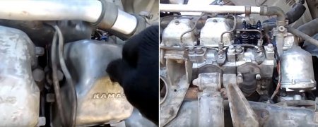
Next, we take and lift the rod of the flywheel lock holder (if there is dirt on it, then clean it in diesel fuel). We lie down under the cabin and remove the flywheel housing hatch cover - this cover has an elongated shape and is secured with two M8 bolts.
We insert a Phillips screwdriver into the hole in the flywheel and turn it in the direction of movement of the engine crankshaft (counterclockwise when viewed from behind the engine). There are 12 ridges or holes visible on the flywheel - its full rotation is also determined by whether all 12 positions have been passed through.
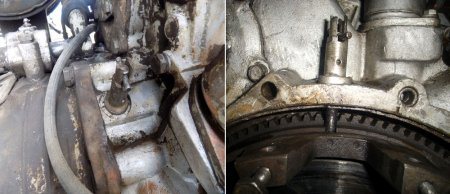
When the flywheel is blocked, we get out from under the cab and check the injection pump marks. For KamAZ-7403.10, KamAZ-740.11 and KamAZ-740.14 engines, the mark of the fuel injection advance clutch in the injection pump drive and the mark on the end of the injection pump must match.
Read more: How long can cargo be transported on a gazelle?
For KamAZ-740.1Z and KamAZ-740.30 motors, the mark on the flange of the driven coupling half in the injection pump drive and the pointer on the injection pump housing must match.
If the marks do not match, then pull the holder rod out of the flywheel groove and climb under the cabin again. We turn the flywheel again until we achieve the desired result. When the marks are set, know that the crankshaft is now in a position that means the start of injection of the fuel mixture in the 1st cylinder.
Now, rotate the crankshaft 60 degrees (2 positions, since the angle between the 1st and 2nd holes in the flywheel is 30 degrees). The adjustment of valve clearances begins with the first pair of heads and is performed simultaneously for 2 cylinders (1 and 5), which follow each other in operating order.
We loosen the locking nut of the adjusting screw and place a feeler gauge of the required thickness into the resulting gap between the rocker arm and the valve.
Use a screwdriver to turn the adjusting screw and set the correct gap ( inlet valve - 0.30 mm, and exhaust valve - 0.40 mm
).
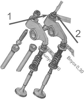
To prevent the screw and nut from turning, hold it with a screwdriver. We insert a 0.3 mm feeler gauge between the intake valve stem and the rocker arm, while simultaneously tightening or lowering the adjustment screw. The result is a slight force when moving the probe between the rocker arm and the rod, while the probe should not bend.
Tighten the locking nut and secure the adjustment screw from turning. We recheck the force with which the probe enters. It is also possible to insert a slightly thicker probe, for example 0.35 mm, but it should not move inward.
Then, take a 0.4 mm feeler gauge and insert it into the slot of the exhaust valve - it should pass with barely noticeable force, but the 0.45 mm feeler gauge should have no movement. In general, the steps for adjusting this valve completely repeat the manipulations with the previous one.
After adjustment, we turn the bar with our fingers without any tools - ideally it should move smoothly, without snagging or stopping. If jamming (kinks) is detected, the rod is straightened or completely changed.
After completing the adjustment of the valves of the 1st cylinder, go to the 5th and repeat all the previous adjustment steps with it.
Next, we climb under the car and immediately turn the crankshaft half a turn (180 degrees) to proceed to adjusting the valves of the 2nd and 4th cylinders. And having finished with them, we turn the flywheel two more times by 180 degrees, according to the data in the table, in order to adjust the remaining valves.

Thus, by turning the flywheel 4 times and adjusting the valves in 2 cylinders each time, you will soon complete the process of setting the correct clearances.
So, the adjustment of the valve mechanism is completed, which means you can now start the engine and evaluate in practice how the sound of the engine has changed as a result.
Various types of ignition
The operation process of the entire KAMAZ vehicle noticeably depends on the moment of injection. If the car begins to ignite early, then the piston is not able to reach the highest position before fuel enters the cavity of the working chamber. Signs of this phenomenon include:
- rigid functioning of the power apparatus;
- the presence of a ringing sound when pressing the gas pedal, which intensifies as the temperature rises on the power device;
- presence of weak traction;
- increased fuel consumption.
During retarded ignition, the piston moves down from its top point and the fuel simultaneously begins to move. The spark lags behind the entire process and completes it. Signs of a late start are as follows:
- presence of white smoke coming from the exhaust system. The more serious the problem, the greater the amount of white smoke;
- incorrect speed of the engine unit;
- too soft functioning of the power apparatus;
- shaking of the engine while smoothly pressing the pedal (increasing torque significantly reduces this effect);
- increased fuel consumption;
- motor overheating;
- poor vehicle traction.
KAMAZ 5320 is... What is KAMAZ 5320?
KamAZ-5320
Total information
KamAZ-740
| Brand: | KamAZ-740 |
| Type: | diesel |
| Volume: | 10857 cm3 |
| Maximum power: | 210 hp, at 2600 rpm |
| Maximum torque: | 637 Nm, at 1500 rpm |
| Configuration: | V8 |
| Cylinders: | 8 |
| Cylinder diameter: | 120 mm |
| Piston stroke: | 120 mm |
| Compression ratio: | 17 |
| Cylinder operating order: | 1-5-4-2-6-3-7-8 |
manual 10-speed
| Manufacturer: | KamAZ |
| Type: | mechanical |
| Number of steps: | 10-speed |
| Gear ratios: | |
| 1st gear: | 7,82 |
| 2nd gear: | 6,38 |
| 3rd gear: | 4,03 |
| 4th gear: | 3,29 |
| 5th gear: | 2,50 |
| 6th gear: | 2,04 |
| 7th gear: | 1,53 |
| 8th gear: | 1,25 |
| 9th gear: | 1,00 |
| Reverse gear: | 7.38 and 6.02 |
| Switching: | floor lever |
The main gear of the drive axles is double, the gear ratio is 6.53.
Can also be 5.43, 5.94, 7.22. Characteristics
Mass-dimensional
| Height: | 2630 (without awning) |
Dynamic
| Max. speed: | 90 km/h. |
On the market
Other
| Load capacity: | 8000 kg. |
| Fuel consumption: | 34 l. |
| Volume of the tank: | 210 l. |
| Designer: | Lev Samokhin, Alexander Setranov, Vsevolod Vyazmin, Georgy Fest |
KamAZ-5320 is a Soviet and Russian three-axle flatbed truck-tractor with a 6x4 wheel arrangement, produced by the Kama Automobile Plant (KAMAZ) from 1976 to 2000. It became the first car model under the KamAZ brand. Intended incl. and for permanent work as a road train with a trailer. The body is a metal platform with opening side and rear sides and an awning. The cabin is three-seater, all-metal, tilting forward, equipped with seat belt attachment points. The main trailer is GKB 8350 of the same size.
History of creation
The prototype of the Future KamAZ 5320 was developed at ZIL and was called ZIL-170. The first ZIL-170 was built in 1968. It had an engine from the Yaroslavl Motor Plant (YaMZ). The American “International COF-220” was chosen as a sample for the prototype, among those purchased abroad for testing and identifying the required class of hooded and hoodless analogues. In the ZiL version, the cabin acquired slightly different, more rectangular shapes and an elegant front end, with the familiar air intake grille on the right side, and 4 main headlights. Already in May 1969, the first prototype of the ZIL-170 vehicle passed its first tests on the Uglich-Rybinsk section. But after the adoption of the resolution of the Central Committee of the CPSU and the Council of Ministers of the USSR “on the construction of a complex of factories for the production of heavy-duty vehicles in Naberezhnye Chelny,” it was decided to transfer further development and subsequent assembly of the ZIL-170 to KAMAZ. At the same time, the name of the ZIL-170 vehicle was changed to KAMAZ-5320. The first, experimental KAMAZ 5320 rolled off the assembly line in 1974.
The first serial KAMAZ trucks rolled off the assembly line on February 16, 1976. According to the tradition of those years, the trucks from the first batch were decorated with the slogan “Our gift to the XXV Congress of the CPSU.”
Based on KAMAZ 5320, the family created the KAMAZ 5410 truck tractor, KAMAZ 5511 dump truck, KAMAZ 53212 extended flatbed truck, KAMAZ 53213 chassis, as well as a family of two-axle analogues (extended KAMAZ 5325 and basic KAMAZ 4325 flatbed, KAMAZ 43 dump truck 255, truck tractor KAMAZ 4410 ). Production of the first two models of the 5320 family began in 1977, the rest - later. All models of this family had a similar design and were largely unified.
Design of the KamAZ-5320 car
The general layout of the KamAZ-5320 is typical for trucks of that time. The three-seater cabin of the car is located above the engine and, using a torsion mechanism, tilts forward, opening access to the engine. The engine, clutch and gearbox form a single power unit mounted on front, rear and support mounts.
Powertrains and transmission
The KamAZ-5320 was equipped with four-stroke V-shaped eight-cylinder diesel engines developed by the Yaroslavl Motor Plant with a working volume of 10.85 liters, a power of 210 or 180 hp, with a maximum speed of 2600 per minute. The diesel engines for the first KamAZ trucks used design solutions that were new to the domestic automotive industry at that time or had not yet found widespread use, for example, a nitrided crankshaft or a full-flow oil filtration system with a centrifuge. Automatic monitoring of the correct operation of the cooling system is carried out by a fluid coupling in the fan drive and two thermostats. The cooling system is made closed and was designed for the constant use of Antifreeze coolant. An air purification system was introduced with a dry-type filter and automatic dust extraction from the filter using an ejector powered by the energy of the exhaust gases. Other innovations include colloidal-graphite coating of the piston skirts, removable metal-ceramic valve guides, molybdenum coating of the lower piston ring, and an active-reactive exhaust silencer. The KamAZ-5320 power units use double-disc clutches. The hydraulic drive of the clutch control mechanism has a pneumatic booster, making it easier to use the pedal. A special feature of the KamAZ tractor transmission is a divider, or multiplier - an additional two-stage gearbox installed after the clutch in front of the main gearbox. One gear of the divider is direct, and the second is overdrive. The gearbox itself is a five-speed one, synchronized in second, third, fourth and fifth gears. The box control is remote, with a mechanical drive. In the divider, the gears are switched by a pneumatic drive. The cardan transmission is an open type and consists of two tubular shafts. Cardan joints on needle bearings with a constant supply of lubricant. The main gear of the drive axles was made double: a pair of bevel gears with spiral teeth and a pair of cylindrical helical gears. A lockable symmetrical center differential is installed in the middle axle.
Suspension
The front suspension springs (semi-elliptical, with sliding rear ends) work in conjunction with double-acting hydraulic telescopic shock absorbers. The rear suspension is of the balancing type. Its springs are also semi-elliptical, with sliding front and rear ends. The leaf springs have a T-shaped section.
Wheels and tires
The car was equipped with discless wheels with removable side and lock rings. Tires are radial type, 12-ply, sizes 260-508R (9.00-20), usually with a universal tread pattern.
Brakes
KamAZ-5320 is equipped with several brake systems: service, parking, auxiliary and spare. The brakes on all wheels are drum type, with two pads. The service brake drive is pneumatic, dual-circuit, with separate action for the wheels of the front axle and the wheels of the rear bogie. When parked, the car is held by the brake mechanisms of the wheels of the rear trolley, which in this case are driven by spring energy accumulators. The auxiliary brake mechanisms are installed in the exhaust pipes of the muffler. Their action is based on creating back pressure in the gas exhaust system through dampers that block the flow sections. In the event of an emergency failure of one of the main systems, the car can be stopped with a spare parking brake. The driver controls the service brakes by pressing a pedal connected by levers and rods to a two-section brake valve. To the right of the driver's seat there is a valve with a parking brake handle. The spare system is activated together with the parking system, and the auxiliary system is activated using a push-button switch located on the cabin floor under the steering column.
Steering
The steering includes a hydraulic booster combined with a steering mechanism.
Calibration KamAZ-740
On 740 truck models, injection timing is determined in conjunction with the installation of the high pressure fuel pump. This requires the following steps:
- raise the cabin to the point where the locking device makes a click;
- lift the flywheel rod slightly and rotate it ninety degrees, then place it in a special recess on the shell;
- unscrew the bolts in the lower third of the cabin and dismantle the shield protecting against contamination;
- install a steel rod with a cross-section of 10 mm and a length of at least 400 mm through the gap in the flywheel;
- turn the crankshaft from left to right until its movement is blocked;
- evaluate the current placement of the fuel injection pump shaft, which is located in the cylinder block; the KAMAZ EURO-2 crankshaft can be replaced if faults are identified);
- align the zero point of the drive coupling with the mark on the pump flange if the coupling is located with the working marks upward. After this, secure the mounting bolts;
- turn the crankshaft if the placement of the part is opposite.
The final stage of setting the ignition is tightening the bolts on the drive coupling and lowering the seating groove. Next comes the installation of the protective cover.
Other ways to set the ignition
In addition to the method described above, the ignition can be set using a strobe light. A stroboscope is a special multifunctional device that can set the ignition with increased accuracy. The car owner needs to direct the rays from the strobe light to the required marks, then put the KAMAZ 65115 euro 2 engine at idle speed and watch them. The formation of a spark in this case will coincide with the flash on the strobe. This allows you to track the current position of the rotating mechanisms.
Another method, developed by amateur craftsmen, but worthy of attention, is to use a 12 V light bulb. In addition to the light bulb itself, you will need a socket and wires with which the light bulb can be connected directly to the car’s power supply. The light bulb must be connected to a wire attached to the distributor at one end and to the main body of the vehicle at the other. Next you need to turn the distributor in the opposite direction. When the light bulb turns on, the process must be stopped, the required position of the housing must be fixed and the nuts tightened. An ordinary light bulb can help set up the operation of such a large vehicle as KAMAZ! The ignition is adjusted in a similar way in KAMAZ Euro 2.
Conclusion
Despite the fact that the diesel power unit has a complex structure, a novice driver is able to understand the design, which is no more complicated than the KAMAZ 43118 Euro-2 PGU. All components are distinguished by their high precision and customization capabilities for each specific vehicle. The injection timing adjustment process can be done even in the field. The design of the engine and other systems in a car is quite complex, so it is necessary to remember: an error of one degree can change the operation of the engine for the worse, and lead to the condition of the unit being unsatisfactory. Understanding the reasons why injection timing fails in a car will help you adjust it less often. The quality of fuel is of no small importance for the operation of the engine and the entire vehicle.
The injection timing requires periodic adjustment, since under changing conditions (temperature, different fuel, etc.) the process proceeds differently. If you correctly adjust the injection timing on KAMAZ Euro 2, the vehicle will show good traction and consume less fuel mass.
How to Adjust Valves on KamAZ 5511
Valve adjustment
KAMAZ
Valve adjustment
Kamaz always causes problems on the car. This is due to the fact that it is very difficult to navigate the piston position and set each piston individually at top dead center (TDC) during fuel injection into the combustion chamber. And to correct it you need to know a certain sequence of actions.
It is recommended to make the adjustment together with a partner, as it is necessary to rotate the crankshaft from the bottom of the machine, and it is recommended to use an inspection hole. There is a special window in the flywheel housing, and there are holes on the flywheel itself. How to adjust the valve on a Kamaz. If a rod of the appropriate diameter is inserted into these holes through the viewing window, it can easily be rotated by the flywheel along the length of the technological window, when the rod lies on one side of the window, another hole appears and the rod moves into it, we can continue to rotate the flywheel. The question is how to adjust the headlights and draw a diagram as if “it’s worth it.” The flywheel should rotate as it goes. rotation of the crankshaft as it rotates when the engine is running. The flywheel housing has a stopper on top. Automotive forum Wroom.ru: discussion of the topic How to adjust the carburetor on the Oka? And on the flywheel. recess, when the plug enters this recess, the flywheel will take a position corresponding to the position of the piston of the first cylinder at TDC.
READ How to Install Wires on VAZ 2109 Trambler
But we need to bring the piston to TDC while simultaneously compressing the fuel in the first cylinder. How to properly adjust the valve on a Kamaz. Therefore, we focus on the brand of high pressure fuel pump (HPF). Once the mark on the injection pump is set during fuel injection into the first cylinder, only then does the locked flywheel move to the correct position.
Adjusting the KAMAZ 740 valve
He made a video about how my grandfather taught me how to adjust a valve
, if something goes wrong, fix it!!!
A simple (grandfather's) way to adjust valves on a KamAZ 740. How to adjust a valve on a Kamaz. KAMAZ 5511 body dimensions; How to apply overlays. And a long-awaited purchase!
EDUCATIONAL FILM, adjusting valves
KAMAZ
engine .
Now remove the stopper and rotate the crankshaft into the two flywheel holes corresponding to a 60 degree rotation angle in this position. the valves of cylinders 1 and 5 are completely closed.
Constantly confused in the direction of rotation of the crankshaft. To test yourself, there is a simple way to stand in front of the cabin and imagine that you are starting the engine clockwise, the flywheel should rotate in that direction, that is, if you rotate the flywheel from below using a rod, the rod will move towards the batteries. So, an adjustable valve for cylinders 1 and 5. Then adjust everything to the carburetor. As the others. How to properly adjust the valve on a Kamaz. how to adjust the valve KAMAZ 5511;. Then rotate the flywheel 6 holes, which corresponds to 180 degrees of rotation angle, and adjust valve . Turn 6 more holes and adjust the valve of 6 and 3 cylinders. And for the last time we rotate 6 holes, adjustable valve
7 and 8 cylinders.
READ Replacement Handbrake Cable Toyota Camry 40
Adjusting the valves itself does not cause any particular difficulties; it is necessary to establish an acceptable gap between the valve
and swing, this is done using an adjusting screw secured with a nut.
Unscrew the locknut, unscrew the adjusting screw, and install the stud between the beam and the valve. It measures 0.35 on the intake valves, 0.45mm on the outlet. How to adjust the valve on the Kamaz Kamaz 5511 charging circuit; How » How to set up. How to adjust the carburetor on Oka? Forum. We unscrew the adjusting screw so that the probe does not tighten and does not move between the beam and the valve , and at the same time this movement should not be free.
Then tighten the locknut while holding the adjusting screw with a screwdriver. After adjustment, install the valve covers. When you start the engine, you will immediately feel that it has become more responsive as the cylinders begin to fire more evenly in relation to each other.