Adjusting the thermal clearances of the engine valves of the GAZ-66 and GAZ-53 cars
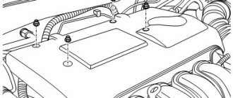
Remove the valve covers.
We turn out the spark plugs.
We set the piston of the first cylinder to top dead center; to do this, close the hole for the spark plug of the first cylinder with your finger and turn the engine crankshaft with the starting handle until air begins to escape from under the finger. This will happen at the beginning of the compression stroke in the first cylinder.
| Rice. 1 |
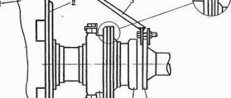
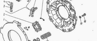
Having made sure that compression has begun, carefully turn the engine crankshaft with the starting handle until the pointer on the clutch housing coincides with the ball cased into the flywheel (Figure 1), and for the GAZ-53 car - until the marks on the crankshaft pulley coincide with the central mark of the pointer c. m, t. (Fig. 2).
| Rice. 2 |
When the piston of the first cylinder is at TDC on the compression stroke, the intake and exhaust valves must be completely closed.
| Rice. 5 |
In this position, we install or check the gap between the rocker arm and the valve stem, which should be 0.25 - 030 mm on a cold (15 - 20 ˚ C) engine.
| Rice. 3 |
It is allowed to reduce the gap to 0.15-0.20 mm for valves located at the edges of the heads: the first and eighth inlet, the fourth and fifth exhaust (Fig. 3).
If the gap does not match: - loosen the lock nut of the adjusting bolt and, by rotating the adjusting bolt, set the required gap on the feeler gauge. Tighten the locknut, holding the bolt from turning, and check the clearance again.
We adjust the clearances of the remaining cylinders in the order of operation of the cylinders 1-5-4-2-6-3-7-8, turning the crankshaft by ¼ turn when moving from cylinder to cylinder.
| Rice. 6 |
To better navigate and speed up the process, use quick-drying paint to mark the drive pulley into four parts (Figure 6).
autoruk.ru
Adjusting valves GAZ 53
Adjusting the GAZ 53 valves is not difficult. It is enough to understand the procedure for performing the adjustment; the procedure will not take much time. A harbinger of the need to adjust the valves is a decrease in vehicle power, an increase in fuel consumption, and the audibility of extraneous sounds from the carburetor and exhaust pipe.
The GAZ 53 valves are adjusted in two simple ways, with a cold engine. The first method involves such actions. The piston of the first cylinder must be installed at TDC, ensuring that the marks on the pulley and the TDC indicator match. Both valves of this cylinder are in the closed state. It is necessary to determine the gap, it can range from 0.25mm to 0.4mm, each driver has his own view of the ideal gap, but the indicators should not go beyond the specified interval. Next, you need to use a screwdriver to hold the adjusting screw of the first valve, which is being adjusted, and gradually loosen the lock nut. Then you need to insert a feeler gauge of a certain size into the gap, turn the adjusting screw until the feeler gauge is clamped between the valve stem and the pressure end of the rocker arm. After this, you need to tighten the adjusting screw and pull out the dipstick. The same procedure is performed on the second valve. After turning the crankshaft 90 degrees, you need to adjust the valves on the fifth cylinder, then turn it another 90 degrees, repeat the procedure on the 4th cylinder. The further order of the cylinders will be as follows: 2-6-3-7-8. Before adjusting the valves on each cylinder, the crankshaft is rotated 90 degrees.
The second method of adjusting the GAZ 53 valves is identical to the first. But there are slight differences. The piston of the first cylinder is installed according to the above principle, the intake valves are adjusted (cylinders 1, 3, 7 and 8), after which the procedure is repeated with the exhaust valves (cylinders 1, 2, 4, 5). Adjustment of the remaining ones is carried out only after turning the crankshaft 360 degrees.
Adjusting the valves on a GAZ 53 car is very simple, does not require much time, it is enough to know the definitions and location of all the parts mentioned above.
If you make the slightest effort and understand the principle of adjusting the valves on the GAZ 53, you can successfully do it yourself, and in the future do it yourself, without visiting a service station or workshop.
More on the topic
awtosowet.ru
History of creation
1937 Dodge Brothers coupe engine Six-cylinder GAZ-63 engine, right side 1 - place where the full-flow fine oil filter "DASFO" should be located 2 - inertia-oil air filter 3 - carburetor 4 - intake manifold 5 - exhaust manifold 6 - installation location pre-heater 7 - pipe for connecting the pre-heater 8 - pipe from the cabin heater 9 - location of the fuel and oil pumps (hard to see) 10 - water radiator 11 - pump (centrifugal pump) 12 - thermostat and outlet pipe to the radiator 13 - block head cylinders 14 - underhood lighting lamp 15 - ignition coil 16 - additional resistor 17 - relay regulator 18 - cable drive for radiator shutters 19 - steering column Six-cylinder GAZ-63 engine, left side 1 - lower pipe to the pump 2 - pump (centrifugal pump) 3 - thermostat and outlet pipe to the radiator 4 - oil filler neck 5 - DC generator 6 - water radiator 7 - steering mechanism 8 - steering column 9 - car horn 10 - ignition distributor-distributor 11 - vacuum ignition timing regulator 12 - starter 13 - pedal drive for turning on the starter 14 — drive from the gas pedal to the carburetor throttle valve 15 — cable drive for radiator shutters 16 — relay regulator 17 — additional resistor 18 — ignition coil 19 — full-flow plate coarse oil filter 20 — cabin heater valve and hose to it 21 and 22 - crankcase ventilation hoses 23 - cable drives for the carburetor air damper and “manual gas”
While modernizing the design of the M1, GAZ engineers came to the conclusion that the car needed a new engine - the reserves of the old one were almost exhausted. Andrei Lipgart faced a difficult choice - try to create an engine from scratch at the plant, or use a foreign development.
Having analyzed the designs of American engines, we found out that the best option is the six-cylinder lower valve Chrysler flathead https://en.wikipedia.org/wiki/Chrysler_flathead_engine, mistakenly called “Dodge-D5” after the name of the Dodge Series D5
, on which it was installed.
It was a time-tested design, dating back to 1928, that proved to be extremely durable and reliable. The engine developed a fairly large specific power for that time, 22-24 hp. hp/l (compared to 12-15 hp/l for GAZ-A and GAZ-M1). The most important technical innovations are replaceable bimetallic crankshaft bearing shells, a thermostat in the cooling system, 100% oil filtration, plug-in heat-resistant exhaust valve seats, a crankcase ventilation system, automatic ignition timing, oxidized pistons, and a floating oil receiver. Despite the relatively large length of the six-cylinder cast iron block, the dry weight of the Dodge D5 was 310 kg. Moreover, this engine was very technologically advanced; almost no non-ferrous metals were used for the manufacture of parts (with the exception of pistons). Compared to the GAZ-M, the American engine consumed 4-5% less fuel because it operated with a higher compression ratio and had a better organized workflow. When all the pros and cons of the Dodge-D5 were weighed, A. A. Lipgart insisted on allocating funds for the purchase of equipment. In 1937, Lipgart himself went to the USA.
While ordering equipment for the production of 6-cylinder engines, he simultaneously studied the technology of their manufacture.
Having quickly found his bearings, Lipgart made strict demands on both the technology and the equipment ordered, which subsequently ensured the high quality of GAZ “sixes” for many years [ source not specified 763 days
].
The lead designer of the project was Evgeny Agitov, deputy chief designer for engines. Redesigned by GAZ specialists, the Dodge-D5, converted, in addition, to metric dimensions, turned into the GAZ-11, and its modifications lived on the assembly line until the 90s (GAZ-52). The Dodge D5 had cylinders with a diameter of 3¼ inches (82.55 mm), a stroke of 43/8 inches (111.1 mm), and its displacement was 217.76 dm3 (3568 cm3). The same parameters for GAZ-11: cylinder diameter - 82 mm, piston stroke - 110 mm, working volume - 3485 cm3. The GAZ-11 was conceived in two versions: with a cast iron head (compression ratio - 5.6, power - 76 hp at 3400 rpm) and with an aluminum head (compression ratio - 6.5, power - 85 hp. at 3600 rpm).
Before the war, few such machines were made. Production of the M1 was resumed after the war, while preparations were underway for the release of the Victory. Compared to the American model, the oil system in the GAZ-11 was changed (with a floating oil receiver); in the camshaft drive, the chain drive was replaced by a gear drive (with a textolite driven wheel) modeled on the Chevrolet straight-6 General Motors engine.
In the summer of 1938, prototypes of the engine were tested on a stand, but when introduced into production, numerous technological difficulties arose and “childhood diseases” were revealed, the elimination of which continued until the war. The start of mass production of the engine had to be postponed to February 15, 1940 (128 serial engines were produced in 1940, in 1941-1451).
The senior engineer of the special group for aircraft engines was L. L. Zilpert. In the aviation modification of the GAZ-11, a gearbox was mounted instead of a gearbox; on the first prototypes, one K-23 type carburetor or two M-1 types were installed in the upper part of the engine.
In April 1939, a prototype of the ship modification was manufactured. After eliminating a number of “childhood diseases” by 1941, the design was finalized, and state tests took place between September 29 and October 16. GAZ-11 passed tests with the conclusion “can be adopted by the Navy.” Mass production of the ship modification was not mastered due to the need to increase the production of power plants for tanks.
During the war, engines were required for installation on tanks and self-propelled guns, so the GAZ-11 in its “pure” form was practically not produced during the war years (in small quantities it was used only on GAZ-61 cars and a small batch of GAZ-11-73, manufactured before June 1941), but after the war the improvement of the GAZ-11 was continued. As a result of modernization, GAZ-51, GAZ-12 and GAZ-52 engines appeared.
GAZ-53 valves: adjustment. Trucks
In the 60s of the last century, the Gorky Automobile Plant launched a series of medium-duty trucks. One of them was GAZ-53. Let's find out its technical characteristics and also talk about valve adjustment.
Trucks from the 52, 53 and 66 series were a line of real station wagons for use in the national economy. They provided cargo transportation in industry and were also successfully used in agriculture.
Model history
In 1964, the basic model of the GAZ-53 car was introduced. It was already equipped with a unit from ZMZ with index 58. It was a GAZ-53 (diesel) with a capacity of 115 hp. With. The maximum speed that this engine produced was 85 km/h. However, the model was produced for only one year.
In 1965, the 53A flatbed truck appeared. Engineers managed to increase the model's carrying capacity to four tons. In 1966, a modification for military purposes was released. The ignition of the GAZ-53 already occurred due to sparking.
Production was stopped in 1982, and a total of about 4 million copies were produced.
Interior and exterior design
The appearance of the 53 was very modern. The designers made the cladding more seamless. This especially affected the radiator grille. The gas tank is located under the driver's seat. The tank neck was located at the driver's door, behind the cab. This helped a lot in the future when they began to convert these cars to LPG. Most often, the GAZ-53 body was flatbed and isothermal.
The launch was carried out from an electric starter with a retractor relay. The cabin was equipped with an excellent heater and windshield wipers. The seats were made in the form of a sofa. However, it was comfortable to sit on even in winter.
Carburetor GAZ-53
The truck is equipped with a two-chamber emulsion carburetor. It also features simultaneous opening of the throttle valves with the possibility of a balanced float chamber.
This carburetor has the index K-135. The model differs from previous modifications in some adjustments. If you don’t adjust the parameters, you won’t be able to use it on engines with conventional cylinder heads.
The GAZ-53 carburetor works as follows. The left chamber is responsible for cylinders 5,6,7,8. The right one supplies fuel to cylinders 1, 2, 3, 4.
Transmission
The engine works together with a four-speed gearbox. It was equipped with four forward gears and one reverse. The GAZ-53 gearbox worked normally even in harsh conditions.
The transmission system is built according to a standard design. Rear-wheel drive. The clutch used is a classic single-disc dry clutch. The cardan shaft and cardan transmission mechanism are also implemented according to the classical design.
It must be said that the GAZ-53 box provides for the installation of a transfer case. It will ensure power take-off.
Engine
ZMZ-53 was used as the power unit. This is a diesel eight-cylinder engine. It had a head as well as a cylinder block made of aluminum. The distributors and ignition coil on this engine often failed. Before the need for major repairs, the car traveled about 400 thousand km. The engine could not be called economical. Drivers also often complained about the GAZ-53 valves. Adjusting them was commonplace.
A two-chamber model was used as a carburetor to correct high fuel consumption.
Soviet truck suspension
The GAZ-53 medium-duty truck was equipped with a spring-dependent suspension system. At the front, the car is equipped with telescopic shock absorbers. It is difficult to drive the car because there is no hydraulic booster.
In order to change gear, it was necessary to double-depress the clutch. The cardan transmission consisted of two shafts. Despite many design flaws, repairing the GAZ-53 was not too difficult, and spare parts were quite accessible. Among other problems with the car, there were problems with the valves. We will tell you about them right now.
About self-adjustment of valves
For any engine to operate, it is necessary to have at least two valves for each cylinder. Today, disc-shaped elements are used. On the GAZ-53 car, the exhaust valve is made of high-quality steel. It has a hollow structure. The intake is also made of high quality steel. In order for the heads to cool better, metallic sodium is poured into the body of the element. To increase heat resistance, the chamfer of the exhaust valves is welded with a special alloy. The rods have special grooves for crackers. They connect the valves and the spring plate.
In order to ensure better filling of the cylinder with the fuel mixture, the plate on the exhaust valve has a larger diameter than on the exhaust valve.
When a GAZ-53 diesel car is started and used, these parts are subjected to very serious loads.
Operating principle
Before we look at valve adjustments, we need to know how they work. Everyone knows that the main task assigned to these parts is the implementation of exhaust and intake. This is gas exchange.
First, the fuel mixture is supplied to the cylinder through the inlet valve, then the combustion products exit through the exhaust element. Closing and opening them is carried out using a camshaft. In order for the valve to return to its place after opening, a special spring is provided. It is very important in this design. When the valve is closed, a spring seals the hole.
GAZ-53 valves - adjustment and the need for clearances
So, this element has a rod and a plate. When the engine warms up to its operating temperatures, the rod heats up and elongates. Therefore, to compensate for such elongation, designers provide special technological gaps between the camshaft cam and the rod.
This gap can only be measured in idle mode. When the unit is already hot, it will decrease or disappear altogether. The rod elongates due to heat. These are the so-called thermal gaps.
When to adjust?
How often do you need to adjust the GAZ-53 valves? Adjustment is necessary when a characteristic noise is heard. It is created by the knocking of rockers and cams. Clearances must comply as closely as possible with the engine manufacturer's specifications. But you shouldn’t focus only on noise. If the valve wears out, then not only the valve will fail, but also the rocker, and with it the cam.
How to adjust valves?
This procedure will not present any difficulty. First you need to find out in what order the setup takes place. You need to regulate according to certain criteria. For example, if engine power has decreased, fuel consumption has increased, and extraneous sounds have appeared from the carburetor and exhaust.
The adjustment is made using very simple methods. If you use the first one, then the piston in the first cylinder must be set to top dead center. For this purpose, there are special marks on the timing pulley. The cylinder valves are closed. We need to find out what the gap is. It can be different: from ideal to very large. Each driver knows his personal ideal clearance on a particular engine.
To adjust, use a screwdriver to hold the adjustment screw on the first valve, and then loosen the locknut. Next, you should insert a test probe of the required size into the gap, and you should turn the screw until it is clamped between the rocker arm and the valve stem. The valve is adjusted. This procedure is also carried out on the second element. Next, to adjust the valves on the remaining cylinders, you need to turn the pulley another 90 degrees. The adjustments are repeated on the fourth cylinder. The order of operations on the cylinders will be as follows: 2 - 6 - 3 - 7 - 8.
If we talk about the second method, it is very similar to the first, but the order will be slightly different. So, the intake valves for cylinders 1, 3, 7, 8 are adjusted, and then the exhaust valves 1, 2, 4, 5. The remaining ones can also be adjusted if you rotate the crankshaft 360 degrees. At this point we can consider the question “how to adjust the GAZ-53 valves” closed. Adjusting them is not very difficult, and it doesn’t take much time either.
As a conclusion
As you can see, valves and the principles of their adjustment are no different from passenger cars. The operation is very simple and does not require too much time. The driver only needs knowledge of the location of these components and a little experience. You will also need a basic set of tools to carry out the setup.
Even a novice driver can handle adjusting the valves, and this way you can save on service station services.
So, we have found out the technical structure and rules for adjusting the valves of the GAZ-53 medium-duty truck.
fb.ru
Linear row of a car plant
It is not surprising that the Gorky Automobile Plant has mastered the production of several types of vehicles at once. In fact, this is how all global companies are developing. But the domestic automobile plant has its own history, built on the historical and political development of the country.
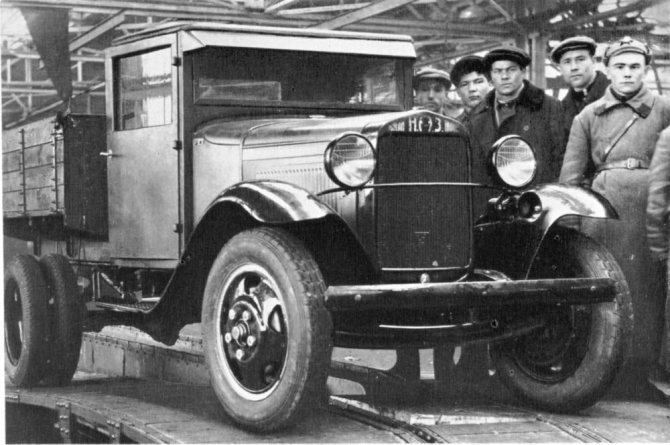
In the photo - the first one and a half ton NAZ-AA truck
In particular, only for the period from 1932 to 1938. The automobile plant in Gorky launched 17 models and became the country's leading automaker, producing almost 68% of all cars produced in the USSR.
Passenger models GAZ
In pre-war times, the plant in Gorky introduced the production of the following models into its production program:
- The first-born GAZ-A had a phaeton body and was produced from 1932 to 1936 at the Gorky Automobile Plant. Beginning in 1933, production of the model began at the Moscow KIM plant. In total, both plants produced 42 thousand cars of this brand.
For reference: Based on the GAZ-A, modifications were produced in the sedan body (GAZ-3 and GAZ-6). And also in the back of a pickup truck (GAZ-4 with a 4x2 wheel arrangement and GAZ-TK with a 6x4 wheel arrangement).
- The famous "Emka" - GAZ-M1, which also had another name "Molotovets-1", was produced from 1936 to 1942. In total, more than 63 thousand cars were produced, including modifications with sedan bodies (GAZ-61-73 and GAZ-11-73); in the body of a phaeton (GAZ-11-40 or GAZ-61-40), as well as in a pickup truck (GAZ-M-415, GAZ-61-417, GAZ-11-415 and GAZ-61-415).
- In the post-war years, the famous “Victory” GAZ-M20 ruled the roost. It began to be produced in 1946, and the model lasted on the assembly line until 1958. In total, more than 235 thousand cars were produced.
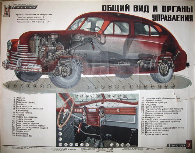
General view and controls of the Pobeda model car
- The Pobeda was replaced by the GAZ-12 ZIM executive sedan. Years of production - from 1950 to 1960, also produced as a medical sedan GAZ-12B. In total, more than 21 thousand cars were produced.
- The most popular car, the GAZ-21 Volga, lasted on the factory assembly line from 1956 to 1970.
For reference: the electrical wiring of the GAZ 21, like its predecessors, was single-wire. The role of the negative wire was performed by the metal body and transmission components. This made it possible to save consumables and simplify car maintenance with your own hands.
- GAZ-13 and GAZ-14 “Chaika” were produced from 1959 to 1989.
- The GAZ-22 Volga station wagon lasted in the car plant’s program from 1962 to 1970.
The GAZ 24 wiring migrated under the hood of the GAZ 3102
- The most popular car, the GAZ-24 Volga, was mass-produced from 1970 to 1985. Had a modification GAZ-24-10 "Volga" (from 1984 to 1992), GAZ-24-11 and GAZ-24-14 (taxi), station wagon GAZ-24-12 and GAZ-24-13 for medical services.
In many ways, the technical characteristics of the electrical circuits of GAZ passenger cars were similar, as can be judged from the data presented in the table below:
| Options | Scheme 21 | Scheme 2410 | Scheme 3102 |
| Network voltage, V | 12 | 12 | 12 |
| Wiring | single-wire | single-wire | single-wire |
| Generator | Alternating current | AC with built-in rectifier | AC with built-in rectifier |
| Distributor | Contact | R119-B | P147 |
| Accumulator battery | 6ST-54 | 6ST-60 | 6ST-60EM |
| Spark plug | A9 or F7 | A17B or A11 | A14D |
| Starter | G53 | ST 230B | S1230B |
| Ignition coil | With additional resistance | B115 | |
| Voltage regulator | PP24 | PP350 transistor contactless | 1337.02 transistor contactless |
- Since 1982, the GAZ-3102 Volga has been mass-produced. Ten years later, the GAZ-31029 Volga appeared.
- The GAZ-3105 Volga sedan lasted on the assembly line until 1998. (see also the article GAZ 3307 wiring diagram: features of the transition model)
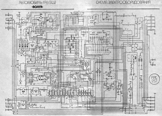
The instructions for the GAZ 3102 also contained a detailed electrical diagram
- After the collapse of the USSR, the GAZ-3110 Volga model remained the leader in the production program from 1997 to 2004. It had station wagon modifications for medical services (GAZ-310221 and GAZ-310231). (see also the article GAZ 3110 electrical wiring: the last attempt for production passenger cars)
- GAZ-3111 “Volga” is another variation of the sedan, produced from 2002 to 2004.
- In 2004, the GAZ-31105 Volga appeared.
- The latest passenger car development, the Volga Siber, appeared on the assembly line in 2008 and remained in the program for 2 years.
GAZ truck models
The cargo sector was developing no less actively.
Starting with drawings of the Ford AA and parts and components purchased abroad, by 1933 the automobile plant in Gorky had mastered the production of a truck entirely from domestic components:
- By the beginning of the Second World War, the first-born GAZ-AA surpassed the milestone of 150 thousand copies and became the most popular truck in the USSR.
Note! A shortage of components constantly plagues the domestic auto industry. In the 30s, these were the starter, battery and tires, which not only were not enough for the assembly line, but were also affected by their short service life.
Modifications - GAZ-AAA was a three-axle truck with a 6x4 wheel arrangement, as well as armored vehicles of the BA series.
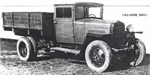
During the war, the famous “one and a half” GAZ-MM-V was produced with one headlight and without a starter
For reference: During the war years we had to save on literally everything. Cabin doors were often covered with tarpaulin, and the roof was made of plywood.
- In total, almost a million GAZ-MM-V units have been produced since 1932. Moreover, only during the Second World War - over 140,000 copies. A lot of other modifications were built on its platform. The most memorable one thanks to the movie is the GAZ-55 ambulance from the film “Prisoner of the Caucasus”.
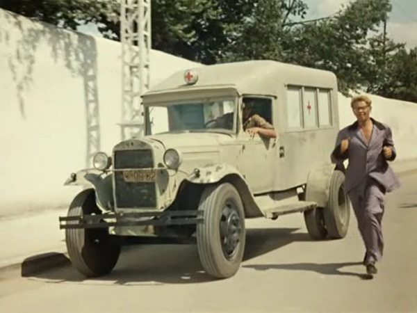
During the war, such a vehicle was used to transport 6-7 seriously wounded people from the battlefield at a time.
- GAZ-51 became the most popular car of the 50-70s with a carrying capacity of 2.5 tons. In total, over 3.5 million copies “ran” on the country’s roads in the post-war years.
- GAZ-52 was a hybrid version with a GAZ-51 truck engine, and the body and transmission were borrowed from the GAZ-53. Thanks to this, the price of the car has decreased.
- GAZ-53 represents the third generation of trucks. It had a unified cockpit and warning lights on the instrument panel along with a clock.
- I would also like to mention the GAZ-3309, produced from 1989 to the present day. Its predecessor, the GAZ-53, made it possible to unify components and systems as much as possible, laying a good foundation.
Adjusting the Gas 3307 and Gas 53 valves
Hello dear friends! Today we will learn how to adjust valves. It would be more accurate to say that we will learn how to adjust the valves correctly. I will describe how I myself adjust the valves on ZMZ 511 engines. Actually, adjusting the valves: where they are adjusted in the usual way (by the term “usual method” I mean a wrench, a screwdriver and a feeler gauge) be it a Gazonchik, be it a Zil or an L engine /ah, yes, at least a diesel engine.
The valves are regulated approximately the same way, you just need to observe how many degrees to turn the crankshaft or camshaft. And necessarily the size of the gap; each engine has its own parameters. (There is even a difference between the intake and exhaust valves, but this is not so critical). I can’t help but say that there are still engines where the valve clearances are adjusted not with a feeler gauge, but with so-called nickels:
that is, the size of the required gap size is adjusted by the thickness of a suitable nickel. Nickels, as I think you guessed, come in different thicknesses and their thickness is measured using a micrometer - microns. So the dimensions are burned out with a laser on them, but it happens that the size is not visible, it is rubbed off, and this is where the micrometer comes to the rescue. This method of adjustment is not yet found on our domestic trucks (I can’t say anything about foreign cars, I don’t know). But on vehicles this method has been used for a long time since the first front-wheel drive VAZs began to be produced since then and is still used today. There is also one type of engine where our intervention is not required, that is, the valves do not need to be adjusted. The valve clearances are regulated by a special hydraulic compensator; or rather, there is no gap; it is compensated by a special hydraulic compensator.
The correct operation of hydraulic compensators depends directly on the oil pressure in the engine. But this is a separate topic, I’ll write about it someday, but not today, and I haven’t digressed much from the topic.
Adjusting valves on the ZMZ 511 engine!
First way!
And since I already said, I will describe how I regulate it myself. So far there have been no problems or complaints.
First of all, you need to open the valve cover and remove the rocker arms.
Why take it off, you ask, then to check if there is wear on the rocker arms. If the engine already has a lot of operating hours, then wear out on the rocker arms cannot be avoided. I indicated where the workings appear with an arrow in the picture.
The plane indicated in the picture should be exactly like this. If there is a waste, then you need to get rid of it. You need to clamp the rocker arms in a vice and use a flat file (rasp) to bring them to such a state that there are no developments. Otherwise you won't have any luck :). And so with each rocker. In this case, it is not necessary to remove the rocker arms from the rocker arm axis, as shown in the picture, you can align it, that is, get rid of the wear and tear in assembled form.
And so we aligned the rocker arms, got rid of the wear, now put the rocker arms in place and continue.
Now remove the ignition distributor (distributor) cover. In general, you can move the distributor cover with the spark plug wires to the side so that they don’t get in the way :). If you are suddenly afraid of getting confused with the order of connecting the high voltage wires from the distributor to the spark plugs, then you can read it, it’s all there. So put the wires with the distributor cap aside, they will only get in the way.
Installing the piston of the first cylinder at TDC.
And now we need to set the piston of the first cylinder to TDC (Top Dead Center) and precisely in the compression stroke. How can we quickly find out exactly the compression stroke or not? We insert the handle for manual start, or whatever it is scientifically called (in some places it is a humpback, and in others it is crooked, I think you understand what I mean). And we turn it until the marks on the crankshaft pulley and in the front engine cover match:
A is a mark on the front cover of the engine, B, respectively, is a mark on the crankshaft pulley. Thus, we set the piston of the first cylinder to TDC.
And so, when these marks coincide, this does not mean that we can start adjusting; we still need to make sure that the compression stroke is exactly in the first cylinder. There are two simple ways:
- You need to unscrew the spark plug from the first cylinder and insert some kind of wad, preferably rubber, instead of the spark plug. And turn the handle until the marks coincide, and it is at the moment the marks coincide in the compression stroke that the wad will fly out, that is, the compression will simply blow it out. And this will be exactly the compression stroke.
- You can also check the compression stroke in a second way, faster than the above. After the marks on the pulley and the front cover match, the distributor slider should point backwards along the direction of the car. This will correspond to the fact that a spark is supplied to the first cylinder of the engine. And the spark is supplied precisely during the compression stroke (If the slider looks forward, this will be compression in the 6th cylinder). That is, I repeat once again: when you turn the engine with the handle, the slider also turns. If marks A and B coincide, the slider should look backward with its contact copper plate (backward along the direction of the car).
Now we have determined the TDC and compression stroke in the first cylinder and we can safely adjust the valves. Set the valve clearances to 0.30 mm and you won’t go wrong. 0.30 the feeler gauge should move with little effort, and 0.25 it should go through easily, then you will have an excellent gap, believe me, I always do this and recommend it to you. And so, after adjusting in the first cylinder, we turn the engine 90°, that is, a quarter turn, and adjust in the fifth cylinder, and so on, etc. Here's the order: 1-5-4-2-6-3-7-8.
Adjusting valves on the ZMZ 511 engine!
Second way!
I still can’t tell you that there is another way to adjust the valves. This is a “two-turn adjustment”, how do you understand this? Yes, very simple:
1. First, still set the piston of the first cylinder to TDC and precisely in the compression stroke. Then adjust the following valves:
- Intake valves of cylinders 1, 3, 7 and 8;
- Exhaust valves of cylinders 1, 2, 4 and 5.
2. Adjust the remaining valves after turning the crankshaft 360 degrees, that is, one revolution. And that is all.
The main thing to remember is that the valves must be adjusted when the engine is cold or no earlier than three hours after it has been turned off. And on summer and hot days even more. But if your car is parked on the street and you are adjusting it in winter, you need to start the engine and let it run for a while, 4-5 minutes will be enough, but no more.
It is also not recommended to adjust the valves on a completely cold engine, especially in winter.
Adjusting the Gas-66 valves on the ZMZ 511 engine!
When adjusting the valves of a Gas-66 with a ZMZ-511 engine, there is no difference, everything is the same as when adjusting the valves of a Gas-3307 and a Gas-53 with a ZMZ 511 engine.
But there is one point. There is simply a difference in the location of the marks on the pulley and the front engine cover. On the Gas-66, the marks are located not on the pulley and cover, but on the back of the flywheel and the casing (rear beam) of the engine. Everything else is exactly the same as on Gaz-3307 and Gaz-53. Here I took some pictures, in case anyone doesn’t know. Open the corresponding hatch on the rear beam of the engine, and you will see a mark and an arrow; everything is visible in the picture.
You can look at the order of operation of the cylinders here suddenly if you are afraid of making a mistake.
Well, let me finish here, today we adjusted the valves on the ZMZ 511.
If suddenly you haven’t found something, or you simply don’t have time to search, then I recommend reading the articles in the “GAS Repair” categories. I am sure you will find the answer to your question, and if not, write in the comments the question you are interested in, I will definitely answer.
To add comments you need to register
gaz3307.ru
GAZ-51 diagram - car diagrams
Schematic wiring diagram of a GAZ-51 and GAZ-63 truck. To enlarge, click on the diagram and then on the icon above the image. The information provided will be useful for independent repair of electrical equipment and troubleshooting in a GAZ-51 car.Electrical diagram of GAZ-51 and GAZ-63
50 3-ST-70-PD Battery (without electrolyte, uncharged) assembled 51-3702029-A Relay-regulator plate assembly 22 51-3704010 Ignition switch assembly 11 51-3707032 Ignition wire holder assembly 51-3709030- B Nut for fastening the central light switch assembly 51-3709038 Spacer washer for the central light switch 51-3709051-B Handle 38 51-3710010 Foot light switch assembly 33 51-3715020 Plug socket for portable lamp assembly (47K) 51-3715021 Gasket for plug sockets ki portable lamp 51-3724015-С1 Main wire bundle, assembled 13 51-3724025-D4 Additional wire bundle, assembled 51-3724030-D Wire bundle along the frame, assembled 51-3724031 Wire bundle to the rear light 25 51-3724036-A2 Connection wires power supply terminals for thermometer, pressure gauge and fuel indicator assembly 51-3724038-B Wires to the lampshade and to the rheostat of the main gasoline tank assembly 48 51-3724050 Wire from the battery to the starter switch assembly 20 51-3724053 Power supply wire for the water temperature control lamp in the radiator assembled 40 51-3724063-A Wire connecting the engine to the body, assembled 12 51-3724063-B Wire connecting the engine to the cabin, assembled 37 51-3724070 Wire connecting the batteries, assembled 51-3724073-B Bracket for fastening wires 51-3724093 Bracket fastening the wire bundle 51-3724097 Lamp wire holder 19 51-3724211 Power supply wire for the heater electric motor switch 54 51-3730010 Trailer power socket assembly, type PS-10 30 51-3806035 Gasoline gauge switch plate 16 51-8102080 Windshield defogger motor assembled 540100 Battery terminal wire lug 540102 Battery terminal wire lug 540114 Battery terminal wire lug 541100 Wire connector assembly 46 63-3724015-K Main wire bundle assembled 53 63-3724030-E Wire bundle ov on the frame assembly 55 63 -3724031 Bundle of wires to the rear light 28 63-3724038-B1 Wire to the lampshade and to the rheostat of the main gasoline tank assembly 51 63-3724062-A Wire connecting the battery to ground assembly 35 69-3724044 Wire connecting the plug socket terminal of a portable lamp with assembled weight 8X-1545 Screw A-14552 Bushing A-14585 Wire fastening bracket A-14598 Bracket A-21 Ceiling lamp 12V 3 light. A-22 Lamp 12 V A-23 Lamp 12 V 1.5 St. trunk light A-24 Lamp 12 V, 3 St. A22 Lamp 12 V 1 St. water temperature in the radiator control AA-17266 Rubber bushing of the wire bundle along the frame in the cross member No. 5 and in the frame brace 10 B1-3705000 Ignition coil assembly 52 BM19-3806000 Additional tank gasoline level indicator sensor assembly 39 BM20-3806000 Gasoline level indicator sensor main tank assembly (51-3806020-B1) 49 VK12-3720000 Hydraulic stop light switch assembly (20-3720010) 4 G21-3701000 12V 18A generator assembly 23 KP5A-3801000 Instrument cluster assembly M-14566 Bracket wire fastenings 43 MM4-3810000 Oil pressure indicator sensor assembly (51-3810020) 6 MM7 Radiator water temperature warning lamp sensor assembly 31 P16-3710000 Gasoline level indicator sensor switch assembly 32 P20-3710000 Panel and lamp light switch assembly P6-3710200 Central light switch thermal fuse (20A) assembly 21 P7-3710000 Central light switch assembly 14 PD1-3714000 Engine compartment lamp assembly PD1-3714201 Engine compartment lamp cap PD1-3714202 Engine compartment lamp cap holder PD1-3714 203 Engine compartment cap spring washer lamps PD1-3714204 Spring of the cap of the engine compartment lamp 17 PD20-3803000D Lantern warning lamp for water temperature in the radiator 26 PK2-3714010-B Lamp assembly PK2-3714200 Lamp rim assembly 24 PP1-3713000 Lamp sockets for instrument scale lighting assembly 27 PP 2-3803000 Control lamp socket for headlight high beam indicator (51-3803028) 41 PR10A-3722000 Fuse block assembly PR10A-3722100 Base of fuse block assembly PR10A-3722200 Cover of fuse block assembly PR10A-3722300 Fuse insert No. 2 for 10A assembly 8 PS1- 3723000 panel of wires to the headlights and spards (three-klemnaya) connecting assembly ps4-3723000 Panel of the connecting wires to the right rear light (two-scanning) assembly (20-3723010-A1) 1 PFZ-3712000-in the fiffarik assembly of 5 p20-3706000. GAZ-51 assembly 15 RR12A-3702000 Voltage regulator relay and current limiter assembly 45 S56-B Two-wire 12V signal assembly 9 SN4-3707000-G M12U spark plug with gasket assembly 47 ST8-3708000 Starter and switch assembly 42 TM2 -3808000-A Water temperature indicator sensor assembly 2 FG2-3711000-A2 Headlight assembly 56 FP13-3716000 Rear lamp assembly
Spark plugs, ignition coil and car ignition wires

12 11-12231 Rubber cap for ignition wires 14 12-3705025 Bracket for fastening the ignition coil assembly 15 12-3707032-G Ignition wire holder assembly 9 12-3707155-B Wire from the ignition coil to the distributor 11 201536-P8 Bolt M12x20 8 250764- P8 Nut M6x1 GAZ-51 252137-P2 Washer 12.OT OST 37.001.115-75 7 293226-P8 Spring washer 6 10 51-3707050-B High voltage wire from the ignition coil to the distributor with interference resistance assembly 2 51-3707090 Wire from the distributor to the spark plug of the first cylinder with an interference resistance assembly 5 51-3707095 Wire from the distributor to the spark plug of the second, fourth and fifth cylinders with an interference resistance assembly 3 51-3707100 Wire from the distributor to the spark plug of the third cylinder with an interference resistance assembly 4 51- 3707115 Wire from the distributor to the spark plug of the sixth cylinder with interference resistance assembly 6 B1-3705000 Ignition coil assembly KL-10-6492 High voltage terminal 1 CH4-3707000-G Glow plug M12U with gasket assembly
GAZ-51 starter circuit
14 1-MAB-31 Insulating contact bolt washer 25 1-MAB-85 Contact bolt bushing 10 1-MAF-12 Insulated starter brush assembly 7 1-MAF-13 Starter brush assembly for ground 15 1-MVV-20-B Starter housing tightening screw 4 1-МЗ-16 Brush holder 6 1-МЗ-19 Starter brush spring 5 1-МЗ-40А Cover bushing on the commutator side 3 1-МЗ-43А Insulating gasket 55 1-МУ-28 Contact bolt 13 1- MU-37 Contact bolt washer 56 1-MU-39 Contact bolt insulating washer 27 1-MU-52 Contact bolt insulating washer 62 1-MU-54 Starter armature thrust washer, rear 38 201454-P8 M8-6gx16 Bolt 34 201460-P8 Bolt M8-6gх30 252135-P2 Washer 8T OST 37.001.115-75 258038-P Cotter pin 2.7x15 GAZ-51 258948-P Pin 5x25 OST 37.001.116-75 43 260031-P8 Pin of the connecting link of the drive activation lever starter 36 260411-P Segment key 3x16 35 51-3708014 Starter pedal roller lever assembly 40 51-3708016-B Starter pedal roller 45 51-3708018-B Starter pedal 42 51-3708020-B1 Starter pedal return spring 39 51-3708 022-B Starter pedal roller bracket 41 51-3708034-B Starter pedal roller thrust ring 37 51-3708045 Starter pedal roller sealing washer 2 60328 Collector side cover assembly 7Х-4279 Screw 19 8Х-1531 M5 nut 21 8Х -1537 Nut M8 20 8Х-1580 Brush fastening screw 8Х-1598 Screw М5х7 ВК14-3708000 Starter switch assembly 28 ВК14-3708005 Contact bolt bushing 32 ВК14-3708030 Flange with fillet assembly 17 ВК14-3708041 Starter switch cover 16 VK14-3708045 Switch cover gasket 29 VK14-3708046 Gasket for the contact bolt 30 VK14-3708047 Contact bolt for the switch 31 VK14-3708053 Terminal bracket for the starter switch 26 VK14-3708060 Plunger with disc assembly 48 M11-40991 Screw for limiting the stroke of the starter drive lever 47 M1 1-90118 Nut M5 33 MAF -10-1358 Gasket MX-0097 Screw M5-8gx12 54 MX-0139 Screw M5 MX-0233 Flange fastening screw 12 MX-0246 Spring washer 8 18 MX-0278 Screw 64 SL-138-88 Cover sleeve on the drive side 52 SL- 8534 Protective tape 60 ST06005 Thrust washer for starter drive 9 ST06200-A Starter armature assembly 11 ST20-3708110 Excitation coil assembly 61 ST20-3708600 Starter drive assembly GAZ-51 51 ST8-3708014 Starter drive activation lever axis 50 ST8-3708015 Saddle lever axis springs 49 ST8-3708016 Lever axis spring 46 ST8-3708020 Starter drive lever assembly 58 ST8-3708050 Intermediate bearing assembly 59 ST8-3708052 Intermediate bearing bushing
Instrument cluster GAZ-51
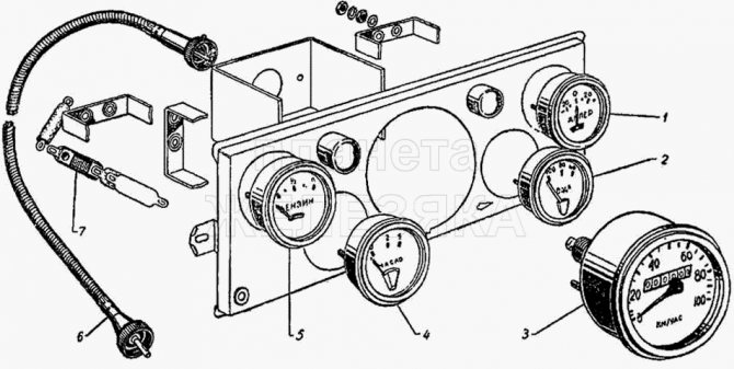
1 AP6-3811000 Ammeter assembly 6 GV16B-3802600-B1 Flexible speedometer shaft assembly GV63B-3802600 Flexible speedometer shaft assembly 7 KP5A-3801400 Resistance water temperature indicator and oil pressure indicator M-14566 Wire fastening bracket 3 SP24-38020 00 Speedometer in GAZ-51 assembly 5 UB26-3806009 Gasoline level indicator assembly 2 UK16-3808000 Water temperature indicator assembly 4 UK18-3810000 Oil pressure indicator assembly
| Fuel saver |
| A new development is a magnetic attachment that reduces the consumption of gasoline or diesel fuel in a car. |