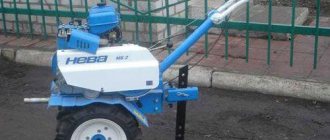
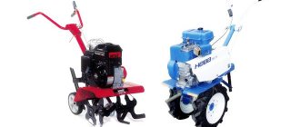
DIY plow drawings
After I got a self-made agricultural winch, which is used for plowing the garden, the question became: should I buy a plow or make it myself?
Walking through the shops and bazaar of Smolensk, you get a strange feeling that the plows produced by the industry for walk-behind tractors are a sad sight. And these industrial creations are suitable only for “picking” and not for plowing the land, and even with the rotation of the layer, and regarding the depth and width of plowing, we can conclude that for planting potatoes with a distance between rows of 60 cm, not one of the proposed ones is suitable in the plow trade. Either our manufacturers are saving money, or the power of the most popular walk-behind tractors is not enough to work with a normal plow with a working width of 30 cm. When planting potatoes, you shouldn’t plow one furrow three times. And the price wants to leave the best - under 2 thousand. rubles (for a couple of pieces of iron from a scrap metal collection point).
The next step to find something useful is to search the Internet. To my surprise, there are 3-4 original descriptions with drawings floating in the vastness of the Russian-language network (this fact surprises me very much). The next step is to look at what those around you are using. It was not possible to buy a suitable plow; the decision was made to make a plow with our own hands. Based on the fact that the plow was supposed to be used for planting potatoes with a winch for plowing, the following requirements are imposed on it:
1. Plowing width – up to 30 cm.
2. Plowing depth -10-20cm.
3. The plow must hold the furrow itself, without digging in or jumping out of the furrow. The geometry of the plow must ensure movement with the specified parameters without the help of a plowman.
4. Possibility of adjusting the depth and width of plowing.
5. Minimum weight and sufficient strength.
My uncle has been using his homemade motorized winch for plowing for more than 10 years and has tried several options. For the last few years, he has settled on an option optimized for a homemade motorized winch for the garden, namely for planting potatoes with a distance between rows of 60 cm. There is also a homemade hiller for a motorized winch and a homemade potato digger, all this can be viewed on the corresponding pages of the site.
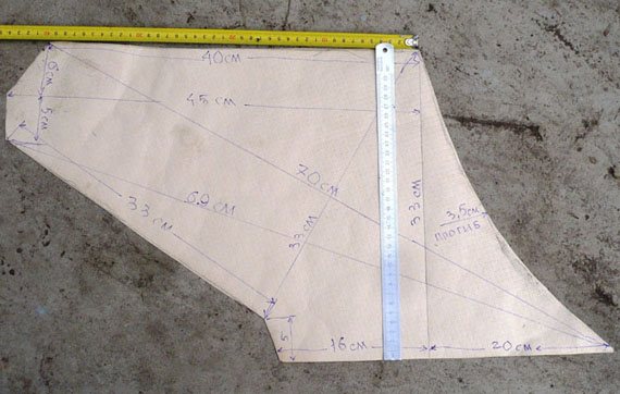
Plow drawing
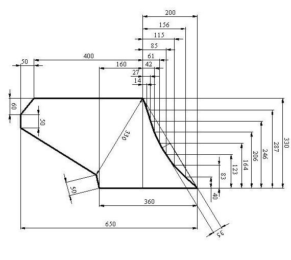
Field board drawing.
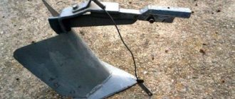
The blade is bent according to this template until the two profiles coincide and then welded at an angle.
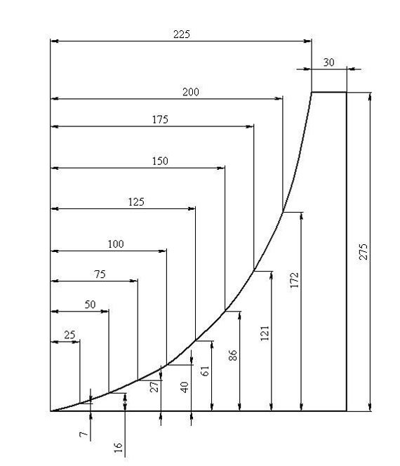
Using a drawing of a homemade plow, you need to draw a template for the plow pattern on thick paper, and then transfer the picture to metal and cut out the blank with a grinder. Personally, I used stainless steel material with a thickness of 1.8 mm. Many often use a sheet of 2-3 mm. The cutting part of the plow is reinforced with a strip of thicker metal. Someone suggests using a disk from a circular machine for these purposes, or a spring from a “Muscovite”. From personal experience, if you plow a summer cottage plot for a family of 4 people in the spring and fall, cultivating six acres, you shouldn’t strive for super-strength. It is more profitable to make a plow that is light but strong enough for its tasks. It’s better to repair or replace something after 10 years, and only if necessary, than to carry around the heavy structure of a homemade plow for 10 years. There is no need for excess weight.
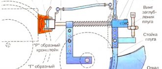
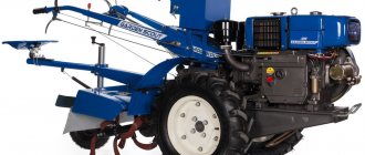
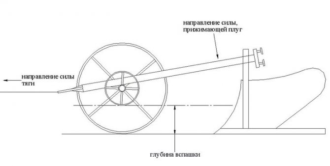
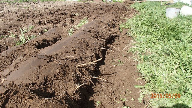
This is what the plowing width adjustment system looks like. By rearranging the large wheel, you can change the plowing width within significant limits. When I plant potatoes, I set the grip to 30 cm, in two passes the distance between the rows is 60 cm. For autumn plowing of the garden or when plowing virgin soil, I use a smaller grip. The small wheel is made so wide that the plow does not press into the ground.
Having looked at the pictures below, you can imagine the basic principles of operation of a homemade plow, or rather a guide system that allows the plow, without the participation of a plowman, to move strictly in a straight line at the established plowing depth and width. The plowing width is regulated by moving the large wheel, which, when the point of application of the traction force is shifted as shown in the figure, is pressed against the furrow, which allows the plow to repeat the direction of the previous furrow. The plow turns slightly, which increases the plowing width. In fact, the width of the nose in the direction perpendicular to the axis of movement of the plow is less than 300 mm, however, the specified width is available for plowing.
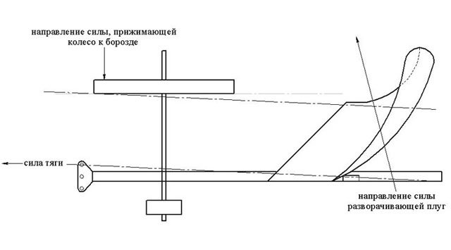
The plow wheel runs along the bottom of the plowed furrow and this situation is observed from the previous furrow to the next. As a result of the application of traction force, a force is exerted to deepen the plow until the plow is aligned with the axis of the wheel, as shown in the figure, as a result, all forces are balanced, and the system operates very stably. Rough adjustment of the plowing depth is carried out by selecting the appropriate difference in wheel diameters, and smooth adjustment is carried out by adjusting the tilt of the plow. At this stage, there was no longer any need to use handles to control the plow, except for some special plowing conditions.
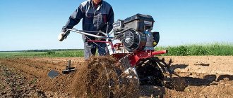
Plows not only loose soil as in the video, but also virgin soil
Kuhn Manager reversible plow
Also check out these articles
- Heap cleaner OVS-25
- Motoblock Centaur MB 2070B
- Grain dryers
- Fungicide Quadris
The ability to select the working width and protection system made the Manager model range ideal for working with medium-power tractors, such as KhTZ-17221, Case Magnum 310, MTZ-2022 and others, and under any working conditions. The maneuverability of the reversible plow allows you to work with high productivity even on small plots. You can work with the same tractor as for a mounted plow, but using a larger number of bodies and working width.
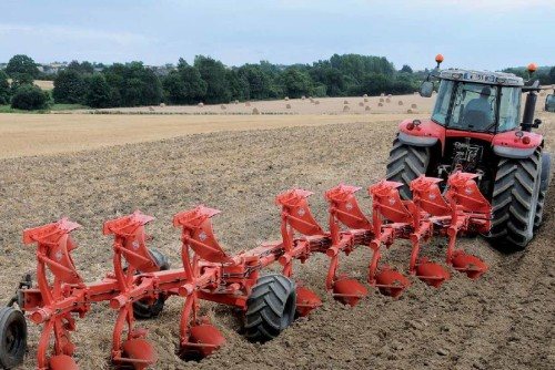
Photo of Kuhn Manager reversible plow
The tilt of the reversing mechanism allows you to smoothly rotate the plow in relation to the direction of movement. The load-bearing wheels are located close to the tractor for an optimal turning radius, which guarantees straightness when exiting the furrow and minimal unplowed space at the edge of the field.
Specially designed plow head articulations provide a rotation angle of 110°.
The support frame of the Kuhn Manager reversible plow allows you to significantly reduce the load on the tractor coupling device during reversal of the plow. This technological solution also allows for a lower center of gravity. The rotation of the plow is carried out by 2 linear hydraulic cylinders, directly connected to the moving parts, without a mechanical system. This extremely simple, wear-free technology does not require special maintenance.
The articulated joint allows the plow to follow the undulations of the working area. Due to this, a uniform plowing depth is ensured. Moreover, when leaving the furrow, when the front bodies are deepened, the rear ones still continue processing. This technology allows for better plowing of field edges and reduced unevenness. The system is automatically locked when the furrow exits (the lock is closed during maneuvering and during transportation) and is released when entering the furrow.
After processing, the soil is ready for the use of other mechanized means, for example, precision seeders, etc.
Technical features of the cabinet Kuhn Manager
- Semi-automatic hitch with variable height - the procedure for attaching and uncoupling is simplified;
- An articulated frame with mechanical adjustment of articulation stiffness ensures structural rigidity;
- Patented bolt-on burst fuses reduce damage to struts during actuation;
- The dumps are made of “Triplex” steel using the most unique hydraulic press in Europe under a pressure of 5000 tons;
- The hardness of the dumps is 9000 vickers - the highest in the industry;
- Single or double acting automatic turning cylinder does not require high oil pressure in the tractor hydraulic system to turn;
- Innovative design of the bolt fuse: it is triggered not by shearing, but by rupture - thereby eliminating the deformation of the body, thereby extending its service life;
- Simplicity, efficiency and durability;
- Only Kuhn Manager and Kuhn Challenger plows have a carriage with two support wheels;
- It is possible to add another building.
Technical characteristics of the Kuhn Manager reversible plow
| Technical specifications | Manager C - 5-case | Manager C - 6-case | Manager C - 7-case |
| Number of cases | 5 | 6 | 7 |
| Maximum tractor power (kW) | 110 | 132 | 154 |
| Maximum tractor power (hp) | 150 | 180 | 209 |
| Prevention | bolt break fuses T | bolt break fuses T | bolt break fuses T |
| Working width (cm) | 35 and 40 | 35 and 40 | 35 and 40 |
| Height under frame (cm) | 80 | 80 | 80 |
| Distance between housings (cm) | 102 | 102 | 102 |
| Frame square section (mm) | 180 | 180 | 180 |
| Type of dumps | cylindrical - screw - strip | cylindrical - screw - strip | cylindrical - screw - strip |
Plow diagram. Diagrams of different plows and their purposes
A standard plow is capable of plowing the ground to a depth of 18-35 cm. There is a smooth method of plowing with plowshare plows, but for better cutting and crushing of the layer, right-hand repellent bodies can be attached to the plow, forming a dump-and-breaker type of plowing.
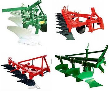
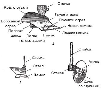
Then, at the slightest deviation to the side from the given direction, the blade crushes the earth into small pieces. A standard plow (plow diagram) consists of a frame, a knife, a skimmer, a coupling mechanism with a tractor, and a body. The plow may have support wheels. There may be several of them, or one. Depends on the design of a particular plow. The body, in turn, is a combination of a ploughshare, a blade and a field wheel. You can see a diagram of a standard plow below:
So here is a complete diagram of the plow:
- - skimmer,
- - plow body,
- - frame,
- - plow knife,
- - support wheel,
- - support wheel adjustment screw,
- — tractor clutch mechanism.
Plow stand: purpose and design
As mentioned earlier, the plow consists of a frame, bodies on which the working parts of the plowing unit are located, a support wheel and a knife. The plow stand is considered as an auxiliary part.
The stand is the load-bearing part of the body. Depending on the land on which the plows are used, there are two types of stands. For example, let’s take a difficult land that no one has looked after for years.
We use a combination body, curved frame and rotary moldboard plow, and this plow has a low tine to handle this type of soil. On the other hand, when we plow on soft ground, we use a plow with a high shank, which is installed on standard flat frame plows.
The body support is either cast or stamped. But most modern plows are made with stamped stands. A saddle is attached to its lower part, to which the body is attached.
Working parts of the plow
No. ___3 Sabaktyn oku-adistemelik zhospary
Educational and methodological lesson plan No. ____
| Top/Group |
| Kuni/Date |
Pәn/ Subject “Agricultural machines”
Takyryp/Topic: Working parts of the plow
Sabaktyn turi/ Lesson type: lecture. presentation
Sabaktyn maksaty/Lesson objectives:_to familiarize students with the structure of the plow
Bilimdilik/Educational: to contribute to the enrichment of students’ knowledge about agricultural production, to promote the activation of their mental activity; to create conditions for establishing a connection between theory and practice, with life phenomena and production processes
Damytushylyk/Developing: continue to develop skills related to the perception and analysis of sources, promote the development of observation and independent comprehension of individual connections, relationships, signs among themselves, continue to develop the skills of a culture of verbal communication;
Tarbielik / Educational: continue to cultivate a positive attitude towards the profession of Tractor Driver, promote the formation of deep cognitive and emotional interest in agricultural production
Sabak turi/ Lesson type: combined
Okytu Adisi/ Teaching methods: verbal, explanatory and illustrative
Bakylau Adisi/ Methods of control: oral
Pәnaralikbalanys/ Interdisciplinary connections: construction of tractors
Korneki Kuraldar, Zhabdyktar, Ulestirme Kagazdar/ Visual aids, equipment, handouts: video material, electronic posters
Sabak Barysy / Progress of the lesson
1. Ұyimdastyru kezenі (amandasu, үgendeu, sabaktyn mіndetі men maksattaryn koyu).
Organizational part (greeting, roll call, setting the goal and objectives of the lesson).
2. Atken takyrypty kaytalau/ Survey and verification of the material covered:
3. Zhana takyrypty bekitu/ Presentation of new material:
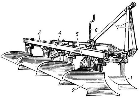
The most common are general purpose plows. The structural elements of the plow are divided into working and auxiliary parts. The main working parts are body 1 (Fig. 2), skimmer 3, knife 4, subsoiler 8; auxiliary - frame 6, support wheel 7 with its adjustment mechanism 2, linkage 5. All working and auxiliary parts are mounted on the plow frame, made up of longitudinal bars, transverse struts and a stiffening beam.
The basis of the plow design is the frame. Working parts are installed on it - housings, skimmers, knives, mechanisms for lifting and adjusting the depth of plowing.
The bodies are placed on the frame sequentially with a shift by the working width b towards the non-plowed field (Fig. 3) with some overlap ∆ b = 25...75 mm, which contributes to complete cutting of the layer with small deviations of the plow from straight-line movement.
General structure of a single-body mounted plow: 1 – plow body; 2 – screw mechanism of the support wheel; 3 – skimmer; 4 – disk knife; 5 – attachment; 6 – plow frame; 7 – support wheel; 8 – subsoiler
The distances l between the bodies (along the path of the plow) must be such that it is possible to install skimmers and the plow is not clogged with soil and plant debris. Usually they take l = (2.0…2.2) b. For plows with a body working width b = 35 cm, l = 75 cm, and for b = 40 cm, l = 80 cm.
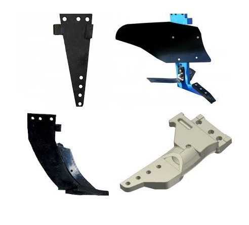
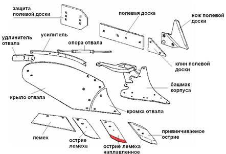
The working parts of a general-purpose plow include a body consisting of a ploughshare, a moldboard, a field board, a stand, as well as a disc blade, a skimmer and a subsoiler.
Plow body
The quality of plowing depends on the design of the plow body, the geometric shape and location of its working surface relative to the bottom and wall of the furrow. Based on the design, there are moldboard bodies, non-mouldboard bodies, cut-out bodies, with a subsoiler, with a retractable chisel, disk and combined ones.
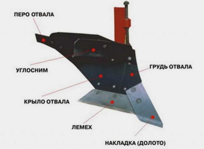
The plow body (consists of a stand, a share, a moldboard and a field board. The share and moldboard form the working surface of the body, which is limited on the field side by the field edge, on the arable side by the furrow edge, and on top by the top edge. The geometric shape of the plow-mouldboard surface of the body determines the appearance and the quality of plowing. The ploughshare cuts the layer from below, lifts it and directs it to the blade. The blade shifts the raised layer, crumbles it, turns it over and throws it into the furrow. A field board is attached to the side of the bottom of the stand, which serves as a support for the body and prevents it from moving towards the unplowed side fields under the influence of soil resistance.
Based on their design, plow bodies are divided into moldboard, non-mouldboard, cut-out, disk and combined. Depending on the type of plowshare-mouldboard surface, cultural, semi-screw and screw bodies are distinguished.
The cultural body crumbles well and satisfactorily wraps the soil layer, so it is used together with a skimmer when cultivating old arable soils.
The half-screw body (Fig. 6, b) wraps well and satisfactorily crumbles the soil layer, so plows with such bodies are recommended for use in cultivating heavily turfed and fallow soils. For full rotation of the formation, half-screw dumps are often equipped with an extension feather.
Screw bodies (Fig. 6, c and d) have a high turning capacity, therefore they are recommended for cultivating virgin lands and plowing perennial grasses.
The designs of special buildings are related to the specifics of the plowing performed. Thus, for plowing heavy soils with intensive crumbling of the layer (for example, for root crops), plows with combined bodies are used (Fig. 6, h). A body of this type, in addition to a shortened plowshare and blade, is equipped with a rotor in the form of a truncated cone, with the large base facing upward, with blades attached to the generatrices. During operation, the rotor, driven from the tractor PTO, intensively crushes the formation coming from the blade with the impacts of the blades. As a result, the degree of soil crumbling increases by 10...20%, the traction resistance of the plow decreases by 25...30%, but the total energy consumption for plowing increases by 13...26%.
The plow body is characterized by the working width b, the working depth a, the angles of installation of the plowshare to the bottom α and the wall γ of the furrow, as well as the shape of the working surface. General purpose plows are equipped with bodies with working widths of 25, 30, 35 and 40 cm, special ones with working widths of 45, 50, 60, 75 and 100 cm.
Working process of the plow body. Moving in the soil, the body cuts off the layer, lifts it, deforms it, crumbles it, wraps it until it comes into contact with the previously fallen layer and sets it in an inclined position.
When plowing with a skimmer, you can plow deeper than without a skimmer.
When deep plowing with plantation plows, the upper part of the layer is cut off with a special skimmer body and dropped to the bottom of the furrow, and the remaining part is lifted and wrapped with the main body.
To prevent the furrows from filling up and to ensure good soil turnover, when cultivating areas located on slopes over 5°, they plow, dumping the layers downhill.
The ploughshare cuts the soil layer in a horizontal plane and directs it to the dump. Depending on the location of the ploughshare in the soil, it has: a field edge facing the field; upper edge, used for joining with the blade; furrow edge facing the furrow (dumped layer); bottom edge, cutting the layer in a horizontal plane. The ploughshare experiences high formation pressure and wears out quickly: it loses its original shape and becomes dull. This can lead to disruption of the plowing process. In addition, as the plowshares become dull, the traction resistance of the plow and fuel consumption increase.
The ploughshare is restored with a quickdraw using hammer blows, using the reserve of metal on its back side (magazine 4). Then the ploughshare is sharpened from the top side to a blade thickness of 0.5... 1 mm. The store's stock is enough for three or four guys.
The shape of the ploughshare is trapezoidal, chisel-shaped, cut-out and triangular.
but they are buried worse and wear out more intensively. Therefore, they are used when cultivating light, old-arable soils. They are installed on skimmers and on some plows.
Chisel-shaped plowshares (Fig. 7, b) have an elongated toe 1 (chisel), bent down 10 mm from the blade line (“depth fence”) and towards the field by 5 mm (“width fence”), due to which they are better buried and more stable in operation, provide a stable plowing depth. These plowshares are designed for heavy soils.
Toothed shares (Fig. 7, c) and shares with a retractable chisel (Fig. 7, d) are used when cultivating very heavy soils.
For plowing rocky soils and uprooted areas at large plowing depths, reinforcement of a ploughshare with a cheek welded from below to the toe, as well as a ploughshare with a chisel, is used.
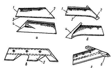
Rice. 7. Types of ploughshares: a – trapezoidal; b – chisel-shaped; c – toothed; g – with a retractable chisel; 1 – heel; 2 – sock; 3 – blade; 4 – store; 5 – tooth; 6 – chisel
To plow soils that are not clogged with stones, plow bodies with self-sharpening plowshares made of double-layer steel or coated with a wear-resistant alloy along the edge of the blade are used. During operation, the upper soft layer, wearing out faster, exposes the lower one (made of sormite alloy 1.7 mm thick or high-alloy steel), which is more wear-resistant, due to which the sharpness of the blade is maintained for a long time, and the service life of the ploughshare increases by 10...12 times.
The blade cuts off the layer from the wall of the furrow, deforms it, moves it to the side and wraps it with the top layer down. Under the pressure of the soil layer sliding over its surface, the blade wears out, and the blade wing experiences a large bending moment. The dump is also subject to impacts from stones, roots, and wood debris found in the soil.
To give the blade sufficient strength, it is made of two or three layers: hard outer surfaces provide sufficient wear resistance of the blade, and a soft inner layer gives it strength - resistance to bending moment and soil impacts.
The moldboard chest experiences especially high pressure, so it wears out more intensively than the wing. Plows working in particularly difficult conditions are equipped with bodies with a replaceable moldboard.
The working surface of the dump is polished to reduce the friction force of the soil and facilitate the sliding of the formation. There should be no dents, burrs, cracks, or corrosive areas, since when such places become stuck with soil, the plowing process is disrupted and the traction resistance of the plow increases.
The ploughshare and blade are attached to the stand with bolts with countersunk heads, which should not protrude above the surface. Drowning of the heads is allowed up to 1 mm. The blade should fit snugly to the ploughshare along the joint line and not protrude above the surface of the ploughshare. A local gap between them of no more than 1 mm and protrusion of the share above the blade of no more than 2 mm are allowed.
The field board ensures stable movement of the body, protects the stand from abrasion and relieves it from the bending moment arising under the influence of lateral pressure of the soil layer.
The field board rests the body on the wall of the furrow. Therefore, the field board experiences great stress and wears heavily, especially at the rear body. It is attached to the stand from the back side at an angle of 2...30 to the wall of the furrow. Sometimes an elongated field board is installed at the rear body or a replaceable heel is attached to the end of the board (Fig.
The bodies of shrub-marsh and planting plows, which experience particularly high forces, are equipped with a wide field board or an extender is installed above the field board.
The stand is the supporting element of all the working parts of the plow body; it is a cast, stamped or welded-stamped part. The stands are high and low. On general purpose plows, high racks are mainly used. The ploughshare and blade are connected with bolts to the saddle located at the bottom of the rack. In the upper part of the stand there is a head for attaching the body to the plow frame with bolts.
The skimmer cuts the top sod layer of soil from the side of the field edge of the body with a thickness of 8...12 cm and a width equal to 2/3 of the working width of the body, and dumps it to the bottom of the furrow.
A ploughshare 10 and a moldboard 6 are attached to the skimmer stand 7 (Fig. 8, a). The skimmer is attached to the plow beam with a clamp 9 using a holder 8.
The skimmer is moved up or down in the holder, changing its depth, and the holder is moved along the beam forward or backward, installing the skimmer at a distance L in front of the body.
The distance L is measured using a square 16 horizontally from the toe of the skimmer share to the toe of the body, and it is selected depending on the working width of the body, the condition and type of soil. For a body with a working width of 35 cm, L=30...35 cm, for a working width of 30 cm - 25...30 cm. When plowing turfy and compacted soil, the skimmer is secured further from the body; poorly connected - closer to the body. If the skimmer extension is insufficient, the layer becomes clogged between the body and the skimmer, and if it is too far, the layer cut off by the skimmer rests against the stand of the body in front. Excessive depth of the skimmer increases the traction resistance of the plow, and the sod layer is poorly sealed.
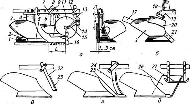
Rice. 8. Installation of the skimmer and disc knife (a), angle grinder (b),
handle (c, d) and flat (e) knives:
1 - heel; 2 — field board; 3 - blade; 4, 7, 18 — racks; 5, 10 — ploughshare; 6 — skimmer blade; 8 - holder; 9, 12 — clamps; 11 — knife disk; 13 — cranked stand; 14 — crown washer; 15 - fork; 16 - square; 17 - feather; 19 - beam; 20 - let's get it down; 21, 25 — bit; 22 - stalk; 23 — knife blade; 24 — handle knife with a curved blade; 26 - flat knife; 27 - skis
Uglosnim20 (Fig. 8, b) is installed on plow bodies for plowing soils clogged with stones. It performs the function of a skimmer, but only cuts off the corner of the formation as it moves along the dump. Uglosnim is a small blade attached to the beam 19 of the body so that its lower corner edge fits tightly to the surface of the blade.
The plows are also equipped with a disk angle cutter, the spherical disk of which cuts the corners of two layers at once, raised by the front and rear located bodies. A layer of soil with two cut corners fits better into the furrow after it has been turned.
The knife plow cuts the soil in a vertical plane along the line of separation of the layer from the massif and promotes better turnover of the layer, embedding of plant residues, ensures stable movement of the plow and uniformity of plowing depth. There are disc knives, handle knives and flat knives with a support ski.
The circular knife (see Fig. 8, a) is a disk 11 that rotates freely on an axis fixed in the eyes of the fork 15. The cutting edge is sharpened on both sides. The fork 15 is freely mounted on the lower end of the crank 13 and can be rotated in a horizontal plane within the limits limited by the crown washer 14. During operation, the knife self-aligns in a plane coinciding with the direction of movement of the plow. The knife stand 13 is mounted on the plow frame using a clamp 12 and an overlay.
The knife can be moved up and down, as well as back and forth along the frame. By turning the rack 13 with a key, you can change the position of the plane of rotation of the disk relative to the field edge of the plow body.
Disc knives are used on general-purpose and shrub-marsh plows for plowing soils that are not clogged with tree roots and stones. To obtain a smooth wall and a clean bottom of the open furrow, the disc knife is usually installed in front of the last body. The center of the disk is placed above the toe of the skimmer or in front of it at a distance of up to 130 mm, the lower edge of the hub is 1...2 cm above the field surface, the plane of rotation of the disk is shifted towards the field from the field edge of the body by 1...3 cm. When plowing turfy soils, disk knives are placed in front of each building. The knives facilitate the separation of sod layers, ensure a constant width of the cut layers and facilitate their correct turnover. This reduces the traction resistance of the plow, improves the quality of plowing and reduces wear on the plowshares and moldboards.
The handle knife (Fig. 8, c, d) is equipped with a straight handle 22, which turns into a blade 23. The knife, which is a dihedral wedge, is attached to the frame using an overlay and a clamp. The knife stand 24 with a curved blade is positioned vertically. A chisel 25 with a hole is welded to the end of the blade, with which it is placed on the cylindrical toe of the ploughshare. Based on the ploughshare, the knife bends less when working on heavy soils.
A knife stand with a straight handle is installed with the blade tilted to the bottom of the furrow at an angle of 70...75°. The knife cuts the soil and small roots, and turns large ones to the surface. The left edge of the knife is placed parallel to the wall of the furrow at a distance of 5... 10 mm from the field edge of the plow body. A knife with a straight blade can be adjusted in height. On turfy soils, the tip of the knife is placed at the same level as the blade of the ploughshare.
Cutting knives are used when plowing turfy soils with unrooted roots and clogged with stones. They are installed on shrub-marsh, forest and other special plows.
A flat knife 26 (Fig. 8, e) with a support ski 27 is installed on bush-marsh plows for plowing soils overgrown with bushes up to 2 m high. Skis are installed to the right and left of the knife, the position of which in height relative to the lower edge of the knife can be changed. The skis press the branches of the bush, the knife cuts them. As the knife, which has two blades, wears out, it is turned at an angle of 180°.
The subsoiler is designed to loosen the subsoil layer without bringing it to the surface.
The frame is used for fastening working parts, as well as mechanisms for installing and adjusting plows.
The plow linkage is used to connect the mounted plow to the tractor.
The support wheel is installed on mounted and semi-mounted plows and serves to adjust the plowing depth. While the plow is working, the support wheel moves along the unplowed edge of the field.
6. Thy tapsyrmasy/Homework p3 in\Voronov Yu
Plow knife description and types
The plow blade removes soil in a vertical plane. The knife is one of the working parts of the plow. By removing the soil, he makes the bottom of a new furrow and thereby creates the depth necessary for the plowman, because the wheels of the plow and tractor follow the knife along the bottom of the furrow. Depending on the land being cultivated, plow knives are divided into handle knives, which are designed to work with forestry and plantation plows, disk knives - they are used in plows with cultural bodies, and flat knives with support skis.
The latter are used in swampy areas, but mostly the first two options are used, since cuttings work well with soil littered with stones.
Disc plow blades
Disc knives are a rotating disk mounted on ball bearings. It is placed in front of the rear wheel. They can also work in swamps, if the area is not clogged with stones.
History of the plow
It is known that people have always treated soil cultivation tools with great respect. Thus, in the Middle Ages, the theft of a plow was considered a serious crime and the thief was punished by being wheeled. It was impossible to take the plow as a mortgage. The one who stood behind the plow was considered an adult
[2].
The etymological dictionary of the Russian language by N.M. Shansky brings the Russian “plow” closer to “swim”: “a plow, compared to a plow, seems to be “floating””[3].
M. Vasmer gives the following explanation of the origin of the word: “Ukr. plow, other Russian plow (More years around 981), Serbian-Tslav. plow, bolg. plow, serbohorv. plow, slovenian plùg, b. n. plúga, Czech. pluh, plouh, slvts. pluh, Polish pɫug, v.-luzh. pɫuh, n.-luzh. pɫug, lab. pläug Borrowing from d.-v.-s. pfluog “plough”, Old Norse plógr, English. plóg, which are partly similar to the modern-century-n. pflegen “to look after”, partly from the new-century-n. Рfloss "peg".
Pre-industrial era
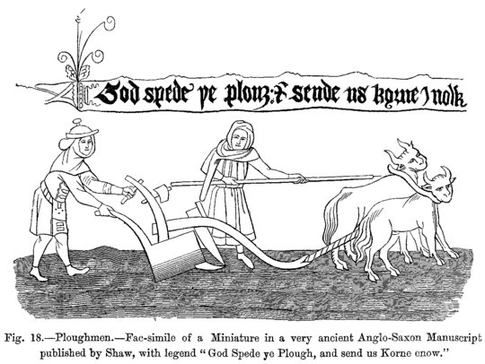
Plowing using a plow and oxen.
Miniature of the poem "God Spede ye Plow", dating back to the beginning of the 16th century. British Museum The very first plows (actually plows) appeared in the 3rd millennium BC. e.[4] and had a very simple structure and consisted of a frame ( drawbar
), holding a vertically fixed piece of wood (
ploughshare
), which was dragged through the top layer of soil. Both the ploughshare and the drawbar were made from one piece of wood, as evidenced, for example, by a Syracusan bronze coin[5].
Ancient forms of the plow are known to us from Babylonian and ancient Egyptian images, rock paintings in Northern Italy and Southern Sweden (dating back to the second millennium BC), as well as from finds of ancient plows in peat bogs in Poland. Earlier than the 1st millennium BC, the plow was known in China.
Horse-drawn plow
Lubor Niederle contrasts the ancient plow (plow) with the classical plow, which was invented by the ancient Romans. Unlike the plow, the plow had wheels and a metal tip. Such a plow made it possible to regulate the depth of the furrow and throw the earth to the side[6]. From the Romans the plow passed to the Germans (German Pflug, English Plough, Swedish Plog), and from them to the Slavs [ source not specified 265 days
]. The Tale of Bygone Years mentions the Vyatichi plow in 981.
At the very beginning, dumps were made of wood in the form of an oblong quadrangle. They were attached to the stand in front, and to the sole
and to one of
handles
by means of a wooden or iron connection. Since the earth sticks to wood more strongly than to metal, subsequently they began to make dumps from cast iron or iron and gave them a shape that was concave in places and convex in others, so that the dump looked like a curved helical surface[5].
The first commercially successful plow using iron parts is the Rotterham Plow.
", developed
by Joseph Foljambe
in 1730 in Rotherham, England.
Industrial revolution
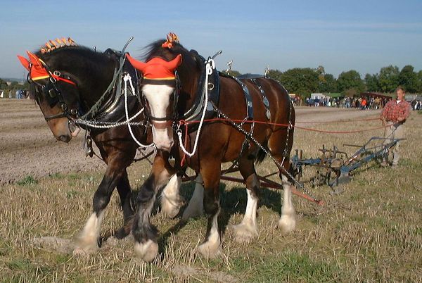
British peasant at the plow
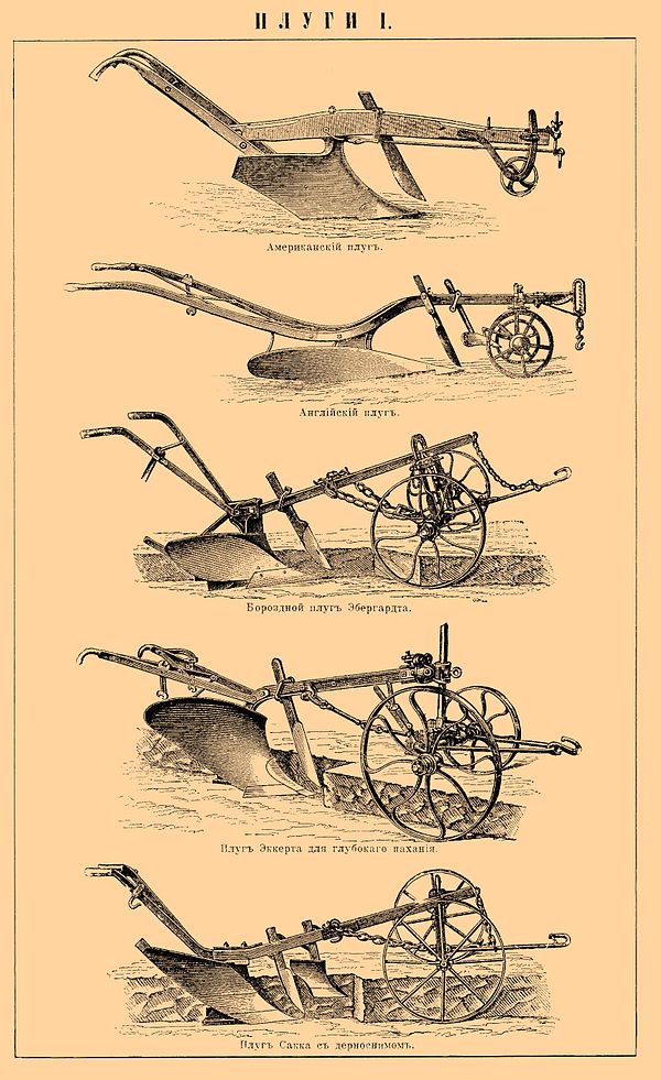
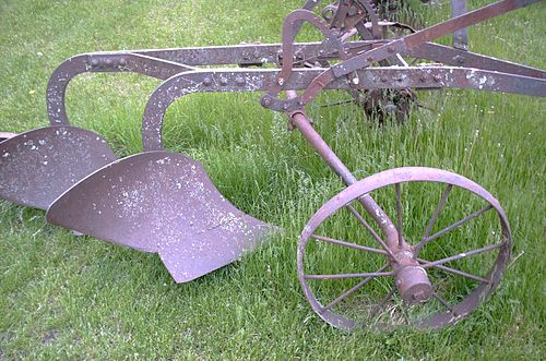
Various plows from the late 19th to early 20th centuries.
Encyclopedia of Brockhaus and Efron Steel plows appeared during the Industrial Revolution. They were lighter and stronger than those made of iron or wood. The first steel plow was invented by American blacksmith John Deere in the 1830s. By that time the drawbar
, attached to the animal harness, was adapted so that the wheel in front of the plow rolled along the ground. The first steel plows were operated by a man on foot. The manager walked behind the plow, holding two handles, and adjusted the direction and depth of the furrow. He also often directed the movement of animals pulling the plow. Later, plows appeared, where the manager was already sitting on a special seat on wheels, and the plow had several plowshares.
One horse can generally only pull the plow for one furrow on clean, soft soil. To cultivate heavier soils, two horses were required, one of which walked along the furrow and the other on the uncultivated ground. For plows that make two or more furrows, one or more horses must walk on free, unplowed land, and even this is difficult for them. Usually such horses are given a ten-minute rest every half hour.
With the advent of the steam tractor, it became possible to use it for plowing. In Europe, balanced plows on wheels were pulled by wire ropes (as a means of transmission), driven by a pair of steam engines by the English engineer John Fowler
(John Fowler). In North America, the hard soil of the plains allowed the direct use of large steam engines for traction power. It often happened that up to ten steam engines pulled one large plow, which made it possible to plow hundreds of acres of land in a day. Only steam engines could move such large plows. When gasoline engines appeared, they did not have sufficient power comparable to steam traction.
In Australia in the 1870s, a special plow was invented for plowing land for vineyards, called the Stump Jump.
"
Its device allowed the plow share to jump over the knobby and very long roots of eucalyptus trees protruding to the surface. With the help of such a plow, the first settlers in the McLaren
cultivated all the oldest vineyards in the region.[7]
A simpler system developed later uses a concave disk (or two) set at a high angle to the direction of travel. The concave surface keeps the disk in the ground unless something solid gets underneath it. When the plow hits a tree root or stone, the plowshare jumps, which made it possible to avoid breaking the plow and continue plowing.
Wheel plow design and application
So, plows are divided into two categories based on the presence of wheels as such. This is a wheeled plow and a non-wheeled plow. The second option is also called hanging. The principle of working with such a plow is to constantly support the plow with the hands of the plowman.
As for wheeled ones, their history goes back 13 centuries in Europe. And previously used in Asia. “Wheeled” means that when the plow is operating, one or more wheels bear the weight of the unit, which is why they are called support wheels. Different devices have different numbers.
Depends on whether the plow is a mounted or trailed type. As a rule, mounted plows have only one field wheel. Trailed ones, which are connected to the tractor through a tow hitch, usually have three wheels - a furrow wheel, a middle (field) wheel, which takes on the load created by the ploughshare and blade when discarding the earth, and a rear wheel. There is also a semi-mounted type of plow that has two wheels.
Contents: Design and operation of a plow Plow diagram How to adjust a plow for plowing Plow blade and its applications Working parts of a plow Plow photo Design and operation of a plow The main working parts of a plow […]
Contents: Instructions: Adjusting the plow PLN 3-35 Plow PLN 5-35: use, description and characteristics Design of the plow and its design Video Plowing with the plow PLN Instructions: Adjusting the plow PLN 3-35 Plow PLN 3-35 […]
Contents: naveska na mtz belorus Why do you need a hitch on MTZ, installation and examples of use MTZ tractor trailer and their types MTZ power take-off shaft - purpose and characteristics […]
Contents: Diagram of the MTZ 82 tractor Electrical diagram of the MTZ 82 tractor Transmission of the MTZ 82 tractor description, photo Diagram of the suspended one on the MTZ 82 Diagram of the MTZ 82 tractor The MTZ 82 tractor is made according to the usual, standard diagram, like […]
Contents: Plow share and general purpose plows General purpose plow. Use and Settings Plow frame - device, description Moldboard plow: pros and cons Suitable plow for T-40 Plowshare and […]
How to install a plow on a walk-behind tractor
Before you start setting up the plow, you need to prepare the walk-behind tractor itself and install the plow on the walk-behind tractor. To do this, the walk-behind tractor is placed at the work site, the wheels with rubber tires are removed and steel lug wheels are installed. This is done in order to reduce the slipping of the walk-behind tractor when plowing due to soil resistance.
After this, they begin to attach the existing walk-behind plow to the attachment. The fastening nuts should not be fully tightened in order to be able to adjust the unit. Then the unit is fixed to the mounting bracket of the walk-behind tractor with two steel pins. Once these operations are completed, the plow adjustment operation can begin.
READ MORE: Do-it-yourself heat gas gun: step-by-step assembly instructions