Scheme UAZ-390995, -220695, -396255 Loaf. Injector.
Scheme UAZ-390995, -220695, -396255 Loaf. Injector.
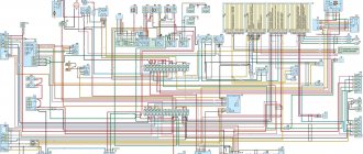
Car electrical circuit diagram.
1 , 50 – front lights; 2 – wind window washer electric pump; 3 – windshield wiper; 4 – windshield wiper and washer switch; 5 – rear fog lamp switch; 6 – alarm switch; 7 – electric motor of the auxiliary heater fan (installed on UAZ-220695, UAZ-390995 and UAZ-396255 vehicles); 8 , 47 – headlights; 9 – additional resistance of the main heater; 10 – main heater fan electric motor; 11 – main heater fan electric motor switch; 12 – additional resistance of the additional heater (installed on UAZ-220695, UAZ-390995 and UAZ-396255 vehicles); 13 – switch for the auxiliary heater fan electric motor; 14 – fuel module; 15 , 56 – side direction indicator lights; 16 , 46 – rear lights; 17 – brake fluid level sensor; 18 – sound signal; 19 – sound signal switch; 20 – fog lamp relay; 21 – external lighting switch; 22 – signaling unit; 23 – speedometer; 24 – interior heater motor fuse; 25 – generator; 26 – starter; 27 – battery; 28 – ground switch (depending on configuration); 29 – license plate light; 30 – fog lamp; 31 – direction indicator switch; 32 – thermal fuse; 33 – instrument cluster; 34 – switch for fuel level sensors in tanks (not installed on UAZ-330395, UAZ-330365, UAZ-390945 vehicles); 35 – emergency oil pressure sensor; 36 – oil pressure sensor; 37 – starter relay; 38 – reversing lamp; 39 – brake light switch; 40 – connecting panel; 41 – coolant circulation pump electric motor switch; 42 – electric motor of the coolant circulation pump; 43 – emergency coolant temperature sensor; 44 – fuel level sensor; 45 – speed sensor; 48 – turn signal and hazard warning relay; 49 – reverse light switch; 51 – foot switch for headlights; 52 – fuse block; 53 – socket for connecting additional electrical equipment; 54 – ignition switch; 55 – brake system status indicator switch; 57 , 59 – interior lamps; 58 , 60 – interior lamp switches.
UAZ wiring diagram: features of modifications with multifunctional control
Did you like the article? Follow our channel for new ideas of useful car tips. Subscribe to us in Yandex.Zen. Subscribe.
It would not be an exaggeration to call the legendary model “452” the ancestor of a whole family of multi-purpose utility vehicles under the UAZ brand. This is true, and experts are well aware that the wiring diagram of the UAZ 3962, components and transmissions of the model 3904, as well as other modifications, are unified with the “452”.
All world manufacturers of passenger cars and utility vehicles are developing in a similar way:
- A successful design serves as the basis for a whole family of cars;
- Constant refinement and modernization allows us to update the model range;
- Unification of parts and components reduces the cost of creating new cars.

For reference: When car owners communicate with each other about the “civilian” version of a particular UAZ unit, this is true. Initially, “452” was created by order of the Ministry of Defense as a vehicle accompanying tank columns on the march. And for use on public roads, the car was modernized.
Wiring diagram for injection UAZ (loaf) – Auto mechanic
It would not be an exaggeration to call the legendary model “452” the ancestor of a whole family of multi-purpose utility vehicles under the UAZ brand. This is true, and experts are well aware that the wiring diagram of the UAZ 3962, components and transmissions of the model 3904, as well as other modifications, are unified with the “452”.
UAZ wiring diagram with conventional steering column switches
All world manufacturers of passenger cars and utility vehicles are developing in a similar way:
- A successful design serves as the basis for a whole family of cars;
- Constant refinement and modernization allows us to update the model range;
- Unification of parts and components reduces the cost of creating new cars.
The famous “Polbaton” - photo of the UAZ 3904 model
For reference: When car owners communicate with each other about the “civilian” version of a particular UAZ unit, this is true. Initially, “452” was created by order of the Ministry of Defense as a vehicle accompanying tank columns on the march. And for use on public roads, the car was modernized.
Find out also about the features of replacing UAZ 3303 wiring.
Platform for conveyor models
The “Loaf”, which became famous, thanks to its all-metal body, the “452” model served as a platform for the creation of an entire line of vehicles:
- UAZ 2206 – a minibus designed for 11 people;
- UAZ 3962 – vehicle for emergency medical services;
- UAZ 396255 - a civilian modification of an ambulance for the needs of rural areas;
- UAZ 39099 – promoted under the name “Farmer”. Designed for 6 passengers and 450 kg of cargo;
- UAZ 3741 – a van for transporting 2 passengers and 850 kg of cargo;
- UAZ 3303 – an onboard vehicle with an open body;
- UAZ 3904 is a cargo-passenger version that combines the convenience of an all-metal body for passengers and an open body for cargo.
For reference: in all modifications, the electrical wiring of the UAZ 2206 is taken as a basis, from which, for each model, unused components that perform certain functions in the car interior have been removed.
The electrical wiring of the UAZ 3909 is identical to the models 3741, 2206 and 3962
Features of the modification with multifunctional control
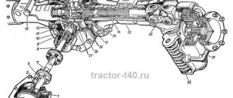
Variations with the car body did not greatly affect its technical equipment. But when changes affected the governing bodies, they underwent modernization:
- Interior wiring for UAZ;
- Steering column control unit for turns and exterior lighting;
- Control unit for the operation of electric windshield wipers on the instrument panel.
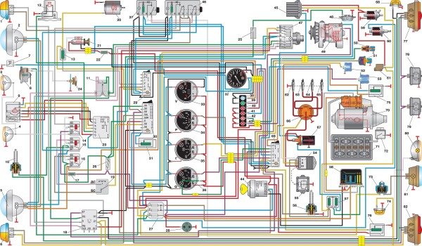
Electrical circuit diagram of a UAZ vehicle equipped with a multifunction steering column switch
Reason for modernization
For reference: according to pan-European safety requirements, when activating light and sound devices while driving, the driver of the vehicle must not remove his hands from the steering wheel. Based on this principle, the wiring diagram for the VAZ 2112 and other models of the Tolyatti Automobile Plant is built.
Old style instrument panel
On cars of the UAZ family, the windshield wiper control unit was located on the instrument panel. And since this did not meet safety requirements, then on all subsequent modifications:
- it was replaced with a more modern multifunctional unit located directly on the steering wheel;
- They began installing a new instrument panel.
New steering wheel switch cluster with new instrument panel
Self-upgrade
Cars of new releases already have a multifunctional control unit in the database. But owners of early editions can re-equip the car with their own hands to meet modern safety requirements.
To do this you will need:
- Original UAZ 2206 wiring - as the most suitable for self-conversion;
- Factory instruction diagram that allows you to correctly connect the steering column switches to the standard diagram;
- Desire to make high-quality installation.
Diagram of a conventional wiper control unit
Advice: the cost of doing it yourself is low, so you should not neglect it when operating UAZ vehicles in dynamic road conditions - on city highways or public roads. As a matter of fact, independently replacing the UAZ wiring on older models will also eliminate its failures.
The work algorithm will be as follows:
- Disconnect the battery;
- We remove the control unit from the instrument panel;
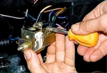
- We disconnect the wires, checking their compliance with the factory diagram in Fig. 1;
- Remove the standard switches from the steering wheel column.
To remodel, you will need to purchase several new parts:
- Block of multifunctional steering column switches from the UAZ 390995 model;
- Relay for the windshield wiper circuit (the VAZ model is best suited, as is wiring 2112, connecting the relay and the switch block);
- Contact blocks in the amount of 3 pieces (one 8-pin for the side of the steering column switches and two 6-pin for the relay and standard adapter).
See also the UAZ 31512 wiring diagram.
New connection diagram for older versions of cars
Advice: a good help for any alteration of the electrical circuit can be the video on the pages of our website, which is shared by car owners who independently service their cars.
Multi-function switch installation process
Let's start installation:
- We replace the standard connector with a new one;
- We cut the 4x4 wire (in Fig. 2 indicated by a red cross);
- We connect its ends to 31V and to the S contact of the windshield wiper relay;
- We connect wire 5-2 to pin 15 of the wiper relay;
- Contact J of the relay is connected to the 2nd contact of the steering column switch;
- We connect the 13-pin relay to ground;
- We connect the new terminal block with an adapter cable;
- We connect it to the block, which was previously connected to the standard switch on the instrument panel;
- We close the contacts of the windshield washer electric motor to contacts 6 and 7 of the switch;
- On the relay, connect pin 86 to pin 6 of the steering column switch.
Platform for conveyor models
The “Loaf”, which became famous, thanks to its all-metal body, the “452” model served as a platform for the creation of an entire line of vehicles:
- UAZ 2206 – a minibus designed for 11 people;
- UAZ 3962 – vehicle for emergency medical services;
- UAZ 396255 - a civilian modification of an ambulance for the needs of rural areas;
- UAZ 39099 – promoted under the name “Farmer”. Designed for 6 passengers and 450 kg of cargo;
- UAZ 3741 – a van for transporting 2 passengers and 850 kg of cargo;
- UAZ 3303 – an onboard vehicle with an open body;
- UAZ 3904 is a cargo-passenger version that combines the convenience of an all-metal body for passengers and an open body for cargo.
For reference: in all modifications, the electrical wiring of the UAZ 2206 is taken as a basis, from which, for each model, unused components that perform certain functions in the car interior have been removed.
Meet UAZ 452
The car was a cargo-passenger version of an off-road vehicle with a 4x4 wheel arrangement. The Ulyanovsk Automobile Plant mastered production of the model back in 1965.
You can evaluate its capabilities by watching the following video:
The UAZ 452 is capable of transporting cargo weighing up to 700 kg in the back. In addition, it can tow a trailer weighing 850 kg. The vehicle became very popular not only in Russian off-road conditions, but was also successfully used in large cities in various capacities (pictured in the article).
- Like a traffic police car;
- As a fire engine;
- Ambulance car;
- Grocery store;
- Utility vehicle, etc.
Wiring diagram for loaf with carburetor engine
To connect electrical appliances to the system of a car with a carburetor, an old-style circuit is used - a loaf designed for UAZ cars produced in 1954 - 1984.
Why might you need a wiring diagram for such a car? The need for instructions for wiring in a car may arise not only if some defect that interferes with the operation of the vehicle is corrected, but also when the wiring is re-installed.
It is worth remembering that there are two circuits for a car with a carburetor engine. The first is a simple one, in which there is no electronic carburetor control unit (this element appeared after 1984 and is not included in the old circuits).
The second is a little more complicated (the connection to the carburetor control unit is taken into account). Such a scheme should be used if it is necessary to connect to the operation of all electronic systems of the car, and not just the ignition and the minimum necessary to drive the vehicle.
To conduct wires according to a simplified scheme, it is enough to stretch a wire from the battery through the toggle switch to the ignition to create a spark, and the second through the relay and button to the starter to make it possible to start the engine.
If the car's generator does not have a voltage regulator built-in, then you need to purchase one and connect it to the system.
Wiring diagram for a loaf with an injection engine.
When repairing electrical wiring in such a car, it is difficult to find a ready-made connection diagram - the manufacturer did not include it in the operating instructions.
It is believed that the wiring diagram for electrical appliances in UAZ loaf cars with an injection engine almost completely corresponds to the diagram that is used in a car with a carburetor, but in reality they are different.
To solve car control problems related to wiring, 2 connection schemes are used - standard for a loaf with a carburetor engine and injection for GAZ - 69 “Kozel”.
Combining the information from these two diagrams allows you to repair or reinstall the wiring in the injection loaf.
Instead of a circuit diagram for an injection GAZ-69, a circuit diagram for an electronic engine control system can be used, so drivers are advised to carry it with them along with a wiring diagram for a loaf carburetor engine.
These sources allow you to manage the wiring of the injection loaf throughout the car, but for some electronic components, if they are not provided for in the standard wiring diagram.
In this case, it is worth contacting specialized forums - more experienced owners of loaves can not only suggest a solution to the problem that has arisen, but also share the circuit that is missing for this, if their car is the same model as the faulty one.
Blog about UAZ
The integrated microprocessor engine control system (CMPSUD) of passenger-and-cargo utility vehicles, UAZ-3741 and UAZ-3909 vans, UAZ-3962 ambulances, UAZ-2206 buses and UAZ-3303 freight vehicles includes an electronic control unit, sensors, actuating electric mechanisms, and diagnostic control malfunction lamp, wiring harness and diagnostic connector.
CMPSUD diagrams of cars of the UAZ-3741, 3909, 3962, 2206 and 3303 families with UMZ-4213, ZMZ-4091 and ZMZ-40911 engines.
On freight-passenger cars of the UAZ-3741, 3909, 3962, 2206 and 3303 models, depending on the engine and its environmental class, a KMPSUD with the following electronic control units and controllers was installed:
— For cars with the UMZ-4213.10 Euro-2 engine — MIKAS-7.2 control unit 291.3763000-11 — For cars with the UMZ-4213.10 Euro-3 engine — MIKAS M10.3 control unit 574.3763000-03 — For cars with the ZMZ-4091.10 Euro engine -3 - control unit MIKAS-11 825.3763001-01 or BOSCH M17.9.7 0 261 S04 795 - For cars with a ZMZ-40911.10 Euro-4 engine - control unit BOSCH M17.9.7 0261 S06 585 for configuration with a mass air flow sensor and BOSCH M17.9.7 0261 S07 322 for equipment with absolute pressure sensor.
CMPSUD diagram of cars of the UAZ-3741, 3909, 3962, 2206 and 3303 families with UMZ-4213.10 Euro-3 engines and the MIKAS M10.3 control unit 574.3763000-03.
Diagram of the KMPSUD wiring harness for cars of the UAZ-3741, 3909, 3962, 2206 and 3303 families with UMZ-4213.10 Euro-3 engines and the MIKAS M10.3 control unit 574.3763000-03.
The composition of the UMZ-4213.10 Euro-3 engine control system with the MIKAS M10.3 control unit, its sensors and actuators are discussed in detail in a separate material.
ECM schematics
General principles for constructing circuits:
The operating voltage of the on-board DC network, at which all actuators and ECM sensors provide the parameters specified in the specifications, must be in the range of 10..14.5V, nominal—12V. All controllers have a non-switchable supply voltage input from terminal “30” of the on-board network to provide a “sleep” mode, which allows you to save adaptive data on self-learning and settings, as well as error codes in the RAM (random access memory) of the controller after turning off the ignition and the ECM main relay.
The exception is controllers, for example, ME17.9.7, which save all necessary data in EEPROM (non-volatile memory) and do not require going into sleep mode.
The controller is activated and goes into operating mode when the on-board voltage is supplied from the ignition switch SA1. Unauthorized engine starting can be blocked by the A4 immobilizer installed on the vehicle.
All power circuits of the ECM and associated electrical equipment are protected from possible damage by short circuit current by fuses F1..F7. Power “Um” to the ECM components is supplied from the main relay KA1. The electric fuel pump M1 is turned on by relay KA2.
Separation of ground circuits according to functional purpose (GNP, GNI, GND, GNA) makes it possible to provide the required engine control parameters (accuracy and speed) in conditions of intense electromagnetic interference created by automotive electrical equipment.
Synchronization of the operation of the ECM with the engine mechanics is carried out using sensors BR1 and BR2, installed respectively on the crankshaft and camshaft.
Low-current pulse circuits of sensors BR1, BR2, B5, B6, B7 and the CAN information bus are protected from interference by shielded shells connected to ground, or can be made with a twisted pair of wires.
Control feedback on fuel supply is implemented using a B6 oxygen sensor, and for Euro-3 circuits a second B7 oxygen sensor is used, which allows you to monitor the efficiency of the converter. Fuel vapors from the tank accumulated in the adsorber are sucked through valve Y5 to the engine inlet.
Knock feedback for correcting ignition timing is implemented using the B5 knock sensor, which detects high-frequency engine vibrations.
Determination of the engine load is traditionally implemented using the B2 mass air flow sensor, which, as a rule, has a built-in air temperature sensor type B4. In rare cases, the BP1 absolute pressure sensor is used for these purposes.
All schemes traditionally use a mechanical throttle drive u1076 with a throttle position sensor B1, which sets the intensity of enrichment or leanness of the fuel supply in variable modes. The exception is the ECM with controllers built on the “electronic gas” principle—the A6 accelerator pedal plus the A7 electromechanical throttle, which eliminates the presence of the Y5 idle speed controller.
Fuel injection is distributed, that is, an injector Y1..Y4 is installed on each cylinder 1..4, and phased - for the ECM with a phase sensor BR2.
The vehicle speed sensor BV1 is used to calculate the vehicle speed, determine the gear number and calculate the fuel consumption per 100 km.
The B8 rough road sensor is used as part of the ECM, which protects the converter from misfires. It allows you to eliminate false misfires caused by uneven engine operation due to heavy vehicle traffic on uneven roads.
To power the sensors, the following is used: Um—on-board voltage from the main relay; 5V or 3.3V—from the controller converter.
To power the actuators, the following is used: “15” and “30”—voltage from the main terminals of the on-board network; Um—on-board voltage from the main relay; Ue—on-board voltage from the electric fuel pump relay.
If a malfunction is detected by the ECM, the controller turns on the HL1 (MIL) indicator.
External diagnostic equipment is connected to the XS1 socket for information communication with the controller via the bidirectional K-line.
Below are the features of the construction and operation of GAZ-UAZ vehicle circuits to comply with Euro-2/Euro-3 toxicity standards.