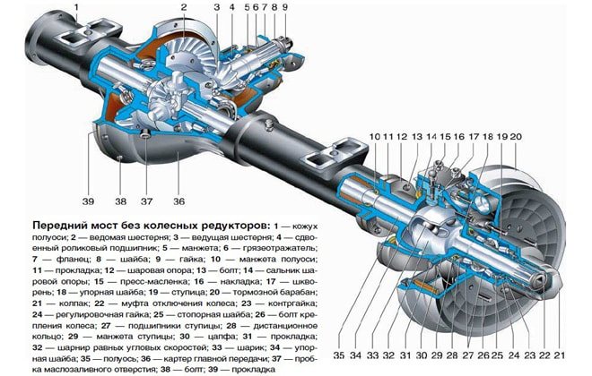
UAZ is a common car on Russian roads. Its design features allow you to move without problems on paved areas, as well as off-road. Repairing the front axle of a UAZ is impossible without knowing the diagram of the wheel gearbox, the design of which is similar to a similar part of the rear axle. The key difference is the peculiarity of fastening and installation of the main gear, the design parameters of the ball bearing located in a special compartment-cup.
Device and characteristics
The design of the UAZ front axle in older models has few differences from the similar design in new models (Spicer). The main differences lie in the design of the crankcase, the dimensions of the components of the drive gear and differential, and in a number of units used.
The design of the old model is in many ways similar to the rear axle of the UAZ and consists of the following components:
- The key place is occupied by the split crankcase, consisting of 2 separate parts.
- Each half is equipped with press-in housings with internal axle shafts.
- Safety valves on the casings, responsible for controlling the growth of oil volume in the mechanism.
- The differential and main gear of the casing are made according to the standard design: a small-diameter drive gear is located in the horizontal plane, in contact with the cardan.
- The large driven gear in the longitudinal plane is in mesh with the main gear. It has a built-in differential of 4 satellites.
- The edges of the crankcase housing are equipped with pivot joints made of ball joints with a rotating housing.
A design feature of the Spicer bridge is the presence of a contact system between the wheel hub and the axle shaft. It is a coupling responsible for connecting and disconnecting 2 elements. The mechanism ensures the transmission of torque to the wheel from the differential. The disconnected clutch leads to free rotation of the wheel on the axle, and the vehicle receives a 4*2 wheel arrangement. The engaged clutch leads to the connection of the hub, differential and axle shaft, the car turns into a 4*4 all-wheel drive.
Old UAZ car models were distinguished by the presence of hubs with drum brake units.
Their wheel rotation angle is no more than 29°. The knuckle and linkage arms connected to each other are a wheelbase control tool. In new models (Spicer), the angle of rotation reaches 32°. The rest of the bridge structure is similar.
What is the difference between a UAZ military bridge and a civilian one?
The military axle, unlike the civilian Spicer front axle, is equipped with final drives. This design feature caused the following differences between military models:
- Gear axles are located 4 cm above the wheels. This difference helps to increase vehicle clearance - the distance between the supporting surface and the bottom of the bridge.
- The main pair is smaller in size and has a small number of large teeth, which increases the reliability of the design. The unit weighs more.
- The gear ratio is 5.38 (traction, but not speed).
- The length of the rear propeller shaft is 1 cm shorter.
Advantages of military bridge models:
- increased ground clearance by 8 cm;
- high torque, allowing you to transport heavy objects, tow and move at low speeds over difficult terrain;
- load evenly distributed between the main and final drives;
- larger teeth increase reliability;
- limited slip differential for off-road driving.
The military design of the UAZ was thought out to accompany tank colonies, which indicates the power and reliability of the design.
Existing types of bridges
Improved bridges on UAZ
- Managed. This is, as a rule, the front axle of the car, equipped with either rear-wheel drive, which is outdated today, or all-wheel drive. But there is another option: in transport equipment for public utilities or agriculture, it is the rear axle that is steered, not the front axle. This type of design is divided into two subtypes.
- Uncut. This is a special beam equipped with a mechanism for steering knuckles, fixed on the sides; wheel hubs are placed on the knuckles. The purpose of this design is to control the rotation of the wheels while driving. The most important conditions are the lightness and strength of the continuous beam. That is why, as a rule, it is made of high-strength steel using forged technology.
- Split. This is already a gearbox equipped with drive shafts. The purpose of the cutting mechanism is to transmit torque to the wheels. The split bridge provides ample opportunities for vehicle maneuvering.
- Supportive. This design is used to increase the lifting power of the machine and acts as an additional supporting element. Without this part, a car designed to transport large cargo would simply fall apart within the first kilometer. The support device can be found in such a unique vehicle as a motor home.
- Continuous leader. This is a rather complex structure, consisting not only of a beam, but also axle shafts, bearings, and a differential. On the beam of this design springs and brackets are attached to secure the suspension. Thanks to the continuous drive axle, the drive wheels can rotate at different rates, in addition, the design softens the load and controls the car when cornering. Some bridge parts undergo additional processing to give them greater strength and elastic properties. Thus, the axle shafts are made of high-quality steel and then hardened with high-frequency heat.
Read also: Ford Mondeo 3 belt
Return to contents
How to turn on the front axle on a UAZ
Engaging the front gear may be necessary if it is necessary to turn from an asphalt road surface onto a country road or terrain with potholes and mud. In the new conditions, rear-wheel drive will not cope with difficulties. Engaged front-wheel drive is a means of solving the problem.
System startup sequence:
- Stop the car and check the operation of the front wheel quick release clutch. It is turned on by turning the wheels clockwise until they stop.
- Move the rightmost lever forward to switch the front wheels to driving status. Now their rotation will be equivalent to the rear.
If the road condition worsens while driving, it becomes more and more difficult to continue driving, the engine stalls, you need to stop the vehicle and engage a lower gear. To do this, you will need to move the middle lever back. In low gear, all 4 speeds are available, and driving becomes easy and smooth again.
After overcoming off-road conditions, it is immediately better to put the middle lever in its original position and move the transfer gearbox to a higher level. On the highway, it is recommended to stop the front-wheel drive and quick-release clutches to save 2 liters of fuel. The measures help reduce noise levels while driving.
Malfunctions and repair work
Common malfunctions of the UAZ front axle and possible repairs:
- Leakage of lubricating fluids. Check the tubes and connecting elements for mechanical damage - the cuffs and flange for functionality, the oil container for the optimal fluid level.
- High wear of fasteners.
- Bearing defects caused by the use of poor quality material by the car plant.
- Broken axle teeth. Adjustment will not help; parts need to be replaced.
- Mechanical defects of the beam.
- Wear of elements. The situation is resolved by replacing it with new spare parts.
- Poor grip of the bearings and main gears indicates the need for tension adjustment.

Bridge repairs begin after diagnosing and searching for the cause of problems in the functioning of the mechanism, which are diverse:
- transmission components of a rear-wheel drive vehicle are faulty due to regular movement over difficult terrain;
- use of consumables and lubricants of unsuitable quality;
- Failure to monitor tire pressure can lead to shaft and bearing failures.
Increasing the service life of the structure
There are several ways to increase the service life of the UAZ structure. The presence of a front axle in a vehicle imposes special requirements for operation. If you monitor and disable the hubs of the axle shafts and wheels at the right time, this will help increase the service life of the mechanism parts when the front-wheel drive is turned off. To prevent mechanical damage to drive components, turn on after the couplings. After switching from off-road to highway, you should immediately switch to rear-wheel drive. Another reason that contributes to rapid wear of rubber is constantly working clutches.
Machine maintenance must meet a number of requirements:
- Periodicity.
- Regular check of main components and mechanisms.
- Timely replacement of worn parts.
- Monitoring the level of oil and other liquids.
- Checking and adjusting wheel bearings.
- Monitoring the functionality of the main gear axial clearance components.
- Use of high-quality consumables and mixtures.
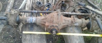
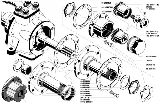
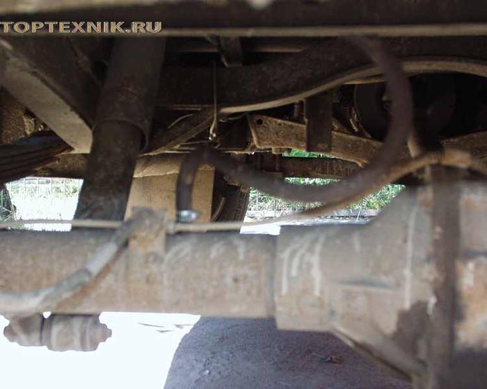
Rear axle structure of UAZ 469
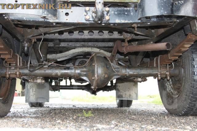
The rear axle of the car is structurally different from the front axle. It does not have a wheel turning mechanism. The rear axle is driven by a cardan shaft from the transfer case. The rear axle consists of the following elements:
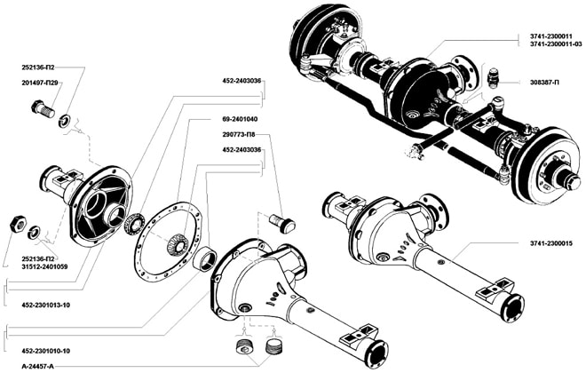
Carter
The crankcase consists of two halves. They are connected to each other using bolts. At the bottom of the crankcase there is a hole for draining lubricant. From the side of the wheel mechanisms, axle housings are pressed into the crankcase. In the front part there is a hole for installing the drive shaft.
REFERENCE: The UAZ-469 model is equipped with two types of bridges - military and collective farm. Depending on the type of bridge, the crankcase design differs.
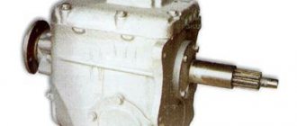
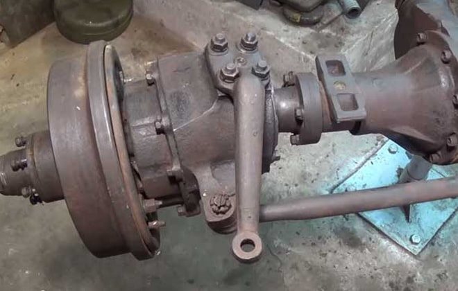
Gearbox
The rear axle of the UAZ 469 has a gearbox consisting of a main gear and a cross-axle differential. The main drive gear is small in size. It transmits torque to the driven gear. The gear teeth are angled. This design allows to reduce the noise level during operation of the unit.
On one side, a drive gear is installed on the drive shaft. On the other side there is a flange necessary for attaching the propeller shaft. To prevent slippage of the drive shaft, splines are provided in the flange. The flange is secured with a nut.
The drive shaft is mounted on bearings. The bearings and moving parts of the gearbox are lubricated with gear oil. To prevent lubricant leakage, oil seals and gaskets are installed.
Inside the driven gear there is a cross-axle differential mechanism. It is made in the form of 4 bevel gears mounted on axles. The cross-axle differential allows the wheels of the axle to rotate independently of each other.
Half shafts
The design of the rear axle of the UAZ-469 provides for the presence of axle shafts. They are necessary to transmit torque to wheel mechanisms. The splined part of the axle shaft is included in the cross-axle differential mechanism. On the other side, the axle shaft is connected with bolts to the hub.
UAZ rear axle bulkhead
Assembly
To assemble a “military” (with final drives) bridge, you need to perform the following steps:
A)
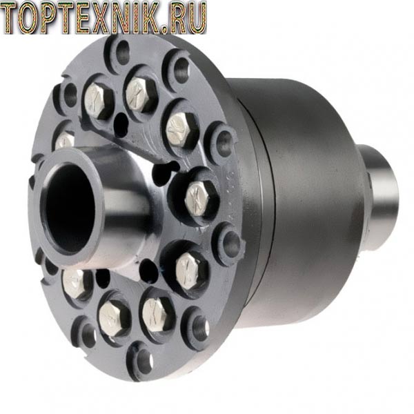
Pressing in the outer rings of all bearings and assembling the satellite box:
1) Completely clean the inside of the axle halves from old oil and dirt. Wash the bridge cavities with solvent.
2) Press the outer rings of the differential bearings into both halves of the axle. Pressing is carried out through a spacer sleeve, for example, an old outer ring of a bearing
3) Press the outer rings of the drive gear bearings into the axle housing.
Outside, you can use 10mm plywood as a spacer
To make pressing easier, you can apply a couple of drops of oil to the outer rings of the bearings and rub them with your finger over the entire surface.
All outer rings are pressed until they are fully seated.
4) Press the bearings onto the journals of the satellite box so that there is a gap of 3-4mm between the ends of the bearings and the satellite box
Be careful when you press on the second bearing. You cannot rest the gearbox on an already pressed bearing, because... it may shift. That is, as shown in the photo, you cannot press on the second bearing.
5) Install the gear box with bearings into the axle housing. Rotate one of the axle halves (the smaller one, the so-called “stocking”) relative to the axle housing to self-install the bearing rollers.
Lift the stocking and install the gasket between the bridge halves. Align the spring pads of the bridge in one plane and evenly tighten the halves of the bridge with a torque of 70-80 H*m.
6) Disassemble the bridge again. Remove the satellite box and use a set of feeler gauges to measure the distances between the ends of the bearings and the satellite box (the previously set gap is 3-4mm). Let's call these distances A and A1. Using the formula B = A + A1 + 0.1, we calculate the required thickness of the gaskets.
7) We divide this distance B approximately in half. Accordingly, we assemble 2 sets of shims. It is advisable to assemble a package of thin gaskets. Gaskets come in thicknesses of 0.1mm, 0.15mm, 0.25mm and 0.5mm. It is better to measure the two packs of gaskets assembled in this way with a micrometer in order to make sure the sizes match.
 We press the bearings (only a two-legged puller is suitable; in the satellite box there are 2 special recesses for its legs)
And install under each selected gasket package
B) Assembling the drive gear (we do not install the gearbox in the axle housing yet):
1) Using a micrometer, measure the height of the old bearing closest to the drive gear teeth. Measure the height of the new bearing. Let's call the difference in height between the new and old bearings the value “A”. If the old bearing is lower than the new one by the amount “A”, then it is necessary to increase the thickness of the adjusting washer located between this bearing and the teeth of the drive gear. If the new bearing is lower than the old one, then increase the height of this washer by this value “A”. The washers are produced in increments of 0.05mm.
If the height of the bearings is the same, then you can install the old washer.
2) Place the selected (or old) washer and press the new bearing onto the drive gear shaft. Next, install a new spacer sleeve and another adjusting washer. The height of the new and old spacers must also be measured. If they are different, then you cannot install the old shim (which is located between the spacer sleeve and the outer bearing). It is necessary to select this washer so as to compensate for the difference in the height of the spacer sleeves. The height of the new bushing is less, then the adjusting washer should be thicker by this amount. And vice versa.
3) Install the drive gear into the axle housing, press on the second bearing, install a washer with an internal sprocket, DO NOT INSTALL the oil seal, but install a flange. The oil seal cannot be installed because it will distort when measuring the breakaway torque.
The flange nut must be tightened with a force of 160 H*m. After tightening the nut, the breaking torque should be measured. It should be within 25-40 H*m. The moment of breaking can be measured with an ordinary household steelyard. The correct starting moment is in the range of 2.5-4kg.
5) If the breakaway moment is greater, then it is necessary to add shims between the outer bearing and the spacer sleeve. And vice versa. The spacers come in 0.05mm increments.
6) Mark the relative position of the nut and flange. Remove the flange and press in the drive gear oil seal. Install the flange.
7) Tighten the flange nut until the marked position is achieved again. We pin it.
B) Adjusting the GP gap:
1) Install the gearbox with adjusted bearings into the axle housing (the drive gear is already installed). Next, we apply paint (you can use any paint, but there are special ones on sale for adjusting the side clearances) on the teeth of the driven (large) gear.
We assemble both halves of the bridge with the gasket, tighten them with bolts with a force of 70-80 N*m.
2) Rotate the flange in both directions long enough.
3) We disassemble the bridge. And look at the contact patch that appears on the paint.
Drawings of correct and incorrect spots should be looked at in the manual.
4) If the lateral clearance spot of the GP is incorrect, then by rearranging the gaskets under the bearings of the satellite box, the satellite box is moved closer and further from the drive gear
By changing the thickness of the gasket under the large bearing of the drive gear, it thereby moves deeper into the bridge (i.e. closer to the satellite box) or outward. The thicker the washer, the more the drive gear extends outward and vice versa.
5) Having achieved the correct contact patch, you can install the axle shafts and assemble the final drive.
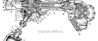
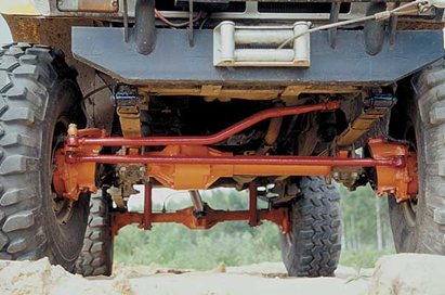
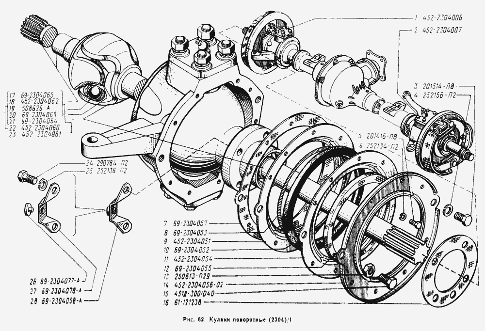
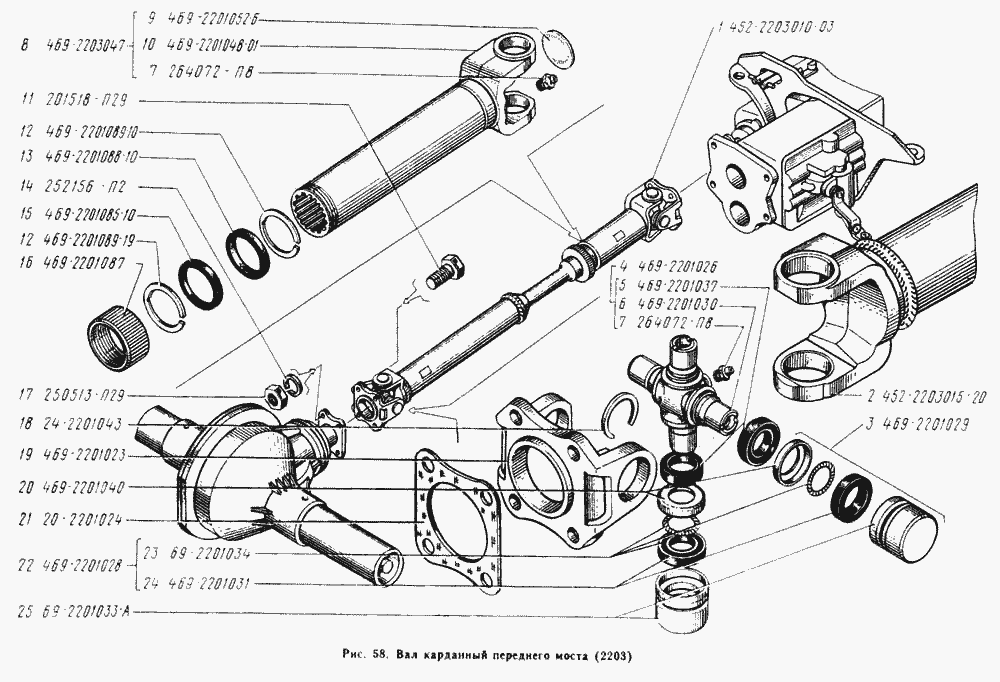
Front axle UAZ 469
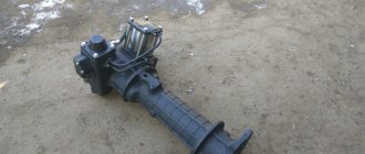
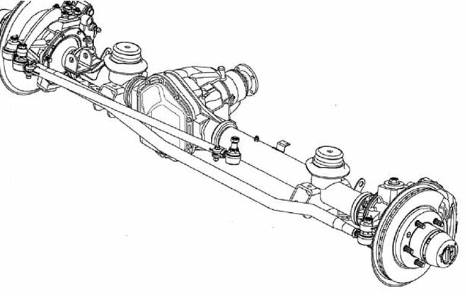
The design of the front axle is different from that of the rear axle. The crankcase is shifted to the right edge in the direction of travel of the car. This is due to the location of the transfer case. The front axle is driven by a driveshaft from the drive shaft. The axle is equipped with rotating mechanisms and steering rods that are used to control the vehicle.
The driver can turn on the front axle on the UAZ 469 without leaving the cabin. To do this, transfer case control levers are installed between the driver and passenger seats. One lever is responsible for turning the front axle on and off. The second is necessary to reduce torque transmission.
Half shafts
The axle shafts have different lengths. This is due to the location of the gearbox. To transmit torque to the wheel mechanisms, regardless of the angle of rotation, CV joints are provided.
IMPORTANT: The design of the front axle of the UAZ 469 provides for disconnecting the axle shafts from the wheel hubs. The connection is made with a specialized screw. This design allows you to increase the service life of the gearbox when driving on good quality surfaces and saves fuel.
Carter
The front axle housing is made of two parts connected by bolts. To avoid pressure build-up when the lubricant heats up, the crankcase is equipped with a breather valve. It allows the air mass to freely escape into the atmosphere. The breathing valve is protected from dust and contamination by a cap.
Steering
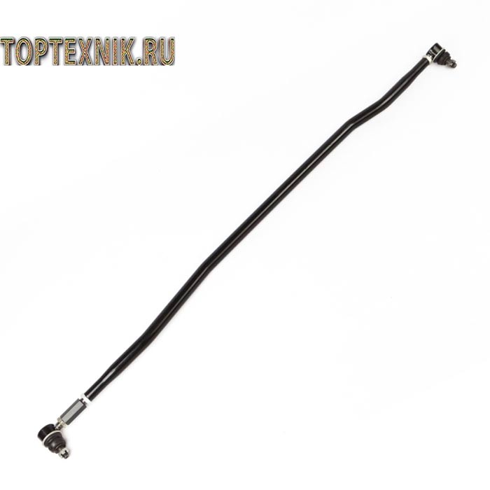
The wheel mechanisms are connected to each other by a transverse rod. The rod connection is hinged. To adjust the wheel toe angle, the rod is equipped with ends with threaded connections.
The forces from the steering column are transmitted to the bipod of one of the steering knuckles. The steering knuckles are equipped with king pins.
Front axle drive UAZ Bukhanka
Cars of the UAZ-452 family, better known by the popular names “Loaf” and “Tabletka,” have all-wheel drive. This factor places special demands on the design of the drive front axle, its reliability and durability.
The front axle of the car is partially similar to the rear axle - the crankcase, main gear and differential of these units are identical and interchangeable. The maintenance and repair cycles for bridges are also similar.
Differences in the design of the front and rear axles begin with the axle shafts. At the front, they transmit torque from the differential to the constant velocity joint (CV joint) mounted inside the steering knuckle.
This part allows you to maintain a constant torque and speed of rotation of the wheels when their axes deviate from the longitudinal axis of the car , for example, when turning. The constant velocity joint is represented by two forks that have guide grooves for four working balls.
In the center of the forks there are semicircular recesses that serve as a supporting surface for the central ball, which ensures the synchronization of the parts. Thrust washers prevent axial displacement of CV joints.
The steering knuckle body is fixed using two kingpins on a ball joint, which, in turn, is detachably connected to the axle housing with five bolts.
During operation, the mechanical elements of the front drive axle are subject to intense wear.
Therefore, if there is no objective need for all-wheel drive on the UAZ-452, for example, when constantly driving on roads with high-quality surfaces, the front-wheel drive is turned off, and sometimes the front hubs are also turned off along with it.
In any case, regular and high-quality maintenance helps to avoid serious damage to the front axle. In this case, it is especially important to pay attention to the maximum wheel rotation angles - they should not exceed 27 degrees.
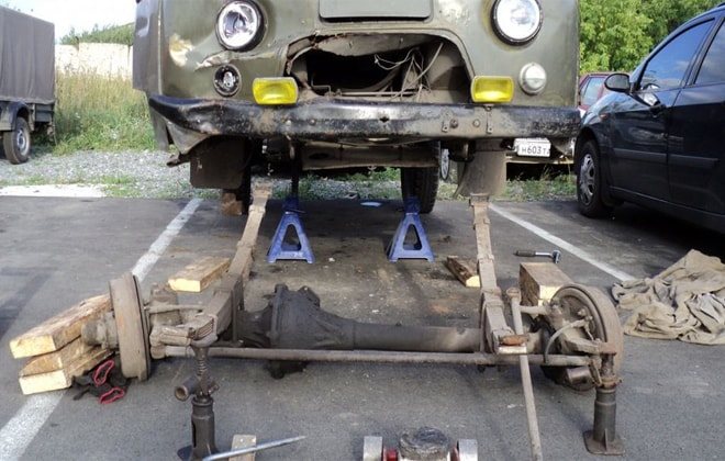
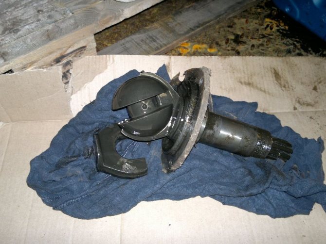
I decided not to touch the differential for now and just work on the steering knuckles and hubs. Therefore, I did not completely remove the bridge; I only removed the ball joints from the bridge stockings. The washing process took a little longer.
During the hike, oil and lithol were poured into the bridge and it froze in a thick layer in the stockings. I picked it out with a stick.
When everything is washed, you can begin the inspection. The right CV joint is new and sticks, the left one is worn out and loose.
I got out of the situation this way. I took both apart. Pulling the balls out of the new CV joint was like a puzzle; I watched how it was done several times on YouTube, twisted and turned, but the ball did not come out. Then somehow, by accident, in the extreme position, the ball popped out. I equalized the wear on the left CV joint with a grinding wheel. I placed the balls from the new CV joint, which turned out to be slightly larger in diameter, on the old one, and the old balls, respectively, on the new CV joint.
Node maintenance
The axles of the UAZ 469 are distinguished by their reliability and durability. For normal operation of units, they must be regularly maintained. To do this you need:
- Inspect the crankcase and wheel mechanisms for lubricant leaks;
- Check the degree of tightening of the fastening bolts;
- Replaces lubricant;
- Clean the breathing valve from dirt and check its functionality;
- Check the integrity of gaskets and seals;
- Check the play of the front axle turning mechanism.
Basic characteristics of the body and engine
Brief description of the UAZ 469 (469B):
- body – steel, open;
- type – frame convertible station wagon;
- number of places – 7;
- number of doors – 5;
- length – 4025 mm;
- width – 1805 (1785) mm;
- height – 2050 (2015) mm;
- base – 2380 mm;
- ground clearance – 300 (220) mm;
- weight without load – 1600 (1540) kg;
- weight with full load – 2400 (2280) kg;
- fuel tank volume – 78 liters;
- maximum speed – 90 (120) km/h;
- ford depth – 0.7 m;
- maximum climbable height with driver and 1 passenger – 57°;
- the maximum climbable height at full load is 31°.
Since the start of production, the UMZ 414 engine has been installed on the civilian modification of the SUV.
Military models were equipped with the same power unit, but with a pre-heater, so the motor has a different index - UMZ 41416.
Engine specifications:
- type – gasoline, atmospheric, 4-stroke;
- number of cylinders – 4;
- arrangement – in-line, vertical;
- operating order – 1-2-4-3;
- cylinder diameter – 92 mm;
- piston stroke – 92 mm;
- engine displacement – 2.5 l;
- compression ratio – 6.7;
- power – 75 l. With.;
- maximum torque – 167 Nm;
- average gasoline consumption on the highway – 10.75 liters per 100 km;
- maximum off-road gasoline consumption – 17.25 liters per 100 km;
- weight of the UMZ 414 engine with attachments and clutch, but without fluids – 163 kg;
- weight of UMZ 41416 with canopies and clutch, but without fluids - 165 kg;
- coolant volume (coolant) – 13 l;
- operating coolant temperature – 80-90°C;
- engine oil volume in the cylinder block – 5.8 l;
- normal oil pressure at idle – 0.5-0.8 kg/cm³;
- normal oil pressure at speed is 2-5 kg/cm³.
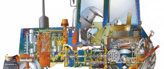
Under the hood of the 469 model
Possible malfunctions and ways to eliminate them
You can repair the front or rear axle of a UAZ 469 yourself. This will require a standard set of tools and minimal technical knowledge. Possible malfunctions:
Presence of oil smudges
The appearance of oil streaks on the crankcase body or at the hub mounting points indicates a violation of the sealing of the unit. The cause of the violation may be failure of the breathing valve. When heated, the lubricant expands and pressure is created in the axle cavity. Under the influence of pressure, the integrity of gaskets and seals is compromised.
To eliminate the malfunction, it is necessary to restore the functionality of the breathing valve and replace the failed seals.
IMPORTANT: When installing gaskets, it is necessary to treat their surfaces with sealant. Lubricant should be added after the sealant has completely dried.
Increased noise
An increased noise level during operation indicates severe wear of the rotating parts or water entering the unit. When driving off-road or fording, water enters the axle cavity through the breathing valve. This leads to poor lubrication of rotating parts.
To prevent water from entering, car owners are upgrading the design of the breathing valve.
To do this, remove the standard cap. Connect the outlet of the breathing valve to a rubber hose. The second end of the hose is secured in the engine compartment.
A crunching sound when the unit operates indicates a malfunction of the bearings. To eliminate the malfunction, it is necessary to replace the failed parts.
Gear failure
When the main drive gears or cross-axle differential fail, an increased noise level or incorrect operation of the unit is observed. For repairs, you need to replace worn components with new ones.
ATTENTION: The main gears are replaced in pairs, regardless of the degree of wear of each of them. Replacing one gear will lead to its rapid failure.
Removing the bridge from the car
In order to repair and adjust the unit, it is necessary to remove the UAZ 469 axle from the vehicle. Dismantling is carried out in the following sequence:
- Place the car on a viewing hole or overpass;
- Immobilize the vehicle with anti-recoil devices;
- Remove the shock absorbers;