| ZIS-150 | |||||||||||||||||||||||||||||||||
| Total information | |||||||||||||||||||||||||||||||||
| Years of production | 1947—1958 | ||||||||||||||||||||||||||||||||
| Assembly | ZIS (Moscow, USSR) ZIL (Moscow, USSR) | ||||||||||||||||||||||||||||||||
| Design | |||||||||||||||||||||||||||||||||
| Layout | front-engine, rear-wheel drive | ||||||||||||||||||||||||||||||||
| Engine | |||||||||||||||||||||||||||||||||
| |||||||||||||||||||||||||||||||||
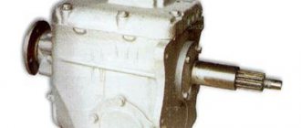
| Transmission | |||||||||||||||||||||||||||||||||
| Type | mechanical | ||||||||||||||||||||||||||||||||
| Number of steps | 5 | ||||||||||||||||||||||||||||||||
| Gear ratios | |||||||||||||||||||||||||||||||||
| 1st gear | 6,24 | ||||||||||||||||||||||||||||||||
| 2nd gear | 3,32 | ||||||||||||||||||||||||||||||||
| 3rd gear | 1,898 | ||||||||||||||||||||||||||||||||
| 4th gear | 1,00 | ||||||||||||||||||||||||||||||||
| 5th gear | 0,81 | ||||||||||||||||||||||||||||||||
| Reverse gear | 6,70 | ||||||||||||||||||||||||||||||||
| Switching | floor lever | ||||||||||||||||||||||||||||||||
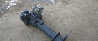
The main gear is double, the gear ratio is 7.63.
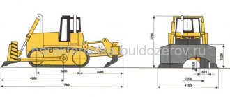
Characteristics Weight and dimensions Length 6720 mm Width 2470 mm Height 2180 mm Ground clearance 265 mm Wheelbase 4000 mm Rear track 1740 mm Front track 1700 mm Weight 3900 kg Dynamic Maximum speed 65 km/h On the market Other Load capacity 4000 kg Fuel consumption 29 l/100 km Volume tank 150 l← ZIS-5ZIL-164 →ZIS-150 on Wikimedia Commons
To improve this article it is desirable:
|
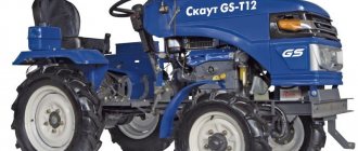
ZIS-150
(from June 26, 1956 -
ZIL-150
) - a Soviet truck produced between 1947 and 1957. In 1957, it was replaced by the ZIL-164 model, which was actually a modernized ZIS-150. 771,883 copies of all modifications were produced.
Model history
| This article or section contains a list of sources or external references, but the sources of individual statements remain unclear due to a lack of footnotes. Claims that are not supported by sources may be questioned and removed. You can improve the article by providing more accurate citations to your sources. |
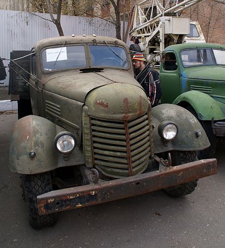
ZIS-150 in the Moscow Museum of Retro Cars
The ZIS-150 truck was supposed to replace the ZIS-5 back in the late 1930s. In 1938, the Stalin Plant built prototypes of the truck, called ZIS-15. This car featured a three-seater all-metal cabin, a modernized 82-hp engine. s., new frame. However, the Great Patriotic War delayed the launch of the model into series for a long time. Only in 1944, at the Stalin Plant, new models of the truck were manufactured, designated ZIS-150, with a front end lining that looked very similar to the American International Harvester K-7.
On October 30, 1947, an installation batch of ZIS-150 trucks was produced. Since pre-war tests showed insufficient engine power, the power on the production car was increased to 95 hp. With. at 2800 rpm. In the design of the ZIS-150, for the first time in the history of the Soviet automobile industry, a five-speed gearbox with constant mesh gears and a pneumatic brake drive were used. Load capacity increased from three to four tons. The car received a new cabin (due to the large shortage [1] in the country of thin steel sheets, it was made of wood and metal: the front tail was made of steel, the doors were wooden) with an efficient heating system and roll-down door windows. The windshield consisted of two halves, the left half was made liftable: it was secured in any position using a rocker mechanism.
The plant completely switched to production of the new model on April 27, 1948, and before that, while a new conveyor was being installed in January 1948, production of the ZIS-5 continued (until April 30, 1948).
In 1950, the car underwent modernization: the carburetor and intake manifold were replaced, and the cabin became completely metal.
On August 18, 1951, production of an improved version of the car was also launched at the Kutaisi Automobile Plant under the KAZ-150 brand. About 80 changes were made to the design of the ZIS-150 at the Georgian plant, in particular, a rear axle from the ZIS-155 bus with an increased gear ratio (9.28 instead of 7.63) was installed, which made it possible to improve the traction qualities of the truck, intended for use by the main way in mountainous areas. Externally, the KAZ-150 differed from the ZIS-150 by a radiator grille with vertical bars and a different tail, partly reminiscent of the GAZ-51, partly of the UralZIS-355M. This was explained by the fact that the head of the design and experimental department of KAZ, A. M. Krieger, previously worked as deputy chief designer of GAZ. [ source not specified 1783 days
]
In February 1956, the ZIS-150 engine had its cast-iron cylinder head replaced with an aluminum one, which made it possible to increase the compression ratio to 6.2 and increase the output to 96 hp. With. power. Other changes include a new carburetor, intake manifold, air filter, reinforced frame, rubber front spring mounts, hydraulic shock absorbers. This modification was named ZIS-150V. Externally, it differed from the ZIS-150 by a radiator grille with vertical bars (not similar to the one that had been used on the ZIL-164 since 1957) and vertical blinds on the sides of the hood.
In June of the same year, after the 20th Congress of the CPSU, the Stalin Plant was renamed the Likhachev Plant. In this regard, at the end of production, some ZIS-150V vehicles received [2] hoods with new stamping “ZIL” instead of the previous “ZIS”.
This modernization was the last - in October 1957, the ZIL-150V gave way on the assembly line to the new model ZIL-164, which was very similar in appearance to the ZIL-150V, but differed in some technical innovations.
According to Soviet technical documentation and using production equipment received from the USSR, Romania and China also began producing their own ZIS-150. In Romania they began to make them under the brand name SR-101 (“Styagul Rosu” - “Red Banner”). The production of trucks here began in 1954 and continued until 1965 (54,224 units were produced; externally, Romanian trucks differed from Soviet ones in their bumper and rectangular cab). In China, in the city of Changchun, since 1956, the Jiefang CA-10 truck (“Jiefan” - “Liberation”) began to be produced by the “Automobile Plant No. 1” (now known as First Automotive Works). With minor changes, the truck was produced until 1986. Its image was placed on Chinese banknotes.
The ZIS/ZIL-150 car was widely exported abroad, mainly to socialist countries. In Mongolia, thanks to good climatic conditions, several copies of the ZIS-150 are still [ when?
] are in operation.
History of creation
The first Soviet armored vehicle ZIS-115 was produced in 1948 by special order of the USSR government, and was a ZIS-110 with armor protection, armored glass, a rear axle with completely unloaded axle shafts and special tires. From 1948 to 1949, 32 ZIS-115s were produced. 8 copies of the car have survived to this day, 1 of which is in Vietnam as a museum copy. Subsequently, the USSR did not produce armored passenger cars until 1983.
Modifications
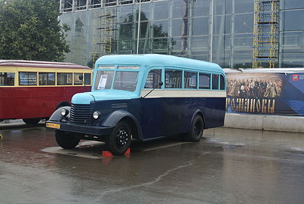
AKZ-1 bus - ZIS-16 body on ZIS-150 chassis
The ZIS-150 model was the base for the production of a large range of construction equipment - cranes, dump trucks, road equipment, timber trucks; special vehicles - harvesters, watering machines, fire trucks, tanks. The units and complete chassis were used to produce buses. The truck was also used in the army. Both standard flatbed trucks and chassis for special equipment went there - radio stations, degassing units, fuel tankers, etc. In 1949-57, using components and assemblies of the ZIS-150 truck, the ZIS-155 bus was produced at ZIS. At the end of 1957, it was replaced on the assembly line by the more advanced ZIL-158. Also on the ZIS-150 chassis were created tanks ATs-4-150 and ATsM-4-150 (Grabovsky Special Vehicles Plant), truck cranes AK-25 (1950), AK-3GS (1951), AK-5G (1953), fire truck PMZ-9, garbage truck MS2 (1950), watering machine PM-8 (1955) and many other special vehicles.
In particular, modifications of the ZIS-150 include:
- ZIS-150P - experimental two-axle all-wheel drive (4 × 4) vehicle (1947);
- ZIS-151 - three-axle all-wheel drive (6 × 6) vehicle (1948-1957);
- ZIS-156 - gas-cylinder (compressed gas) 3.5-ton truck (1949-1957);
- ZIS-156A - gas-cylinder (liquefied gas) 4-ton truck (1953-1957);
- ZIS-253 (UlZIS-253, NAZ-253) is an experimental 3.5-ton diesel truck for production at UlZIS and the Novosibirsk Automobile Plant. Developed independently of the ZIS at UlZIS (1947);
- DAZ-150 “Ukrainets” is an experimental 4-ton truck for production at the Dnepropetrovsk Automobile Plant. Developed independently of the ZIS at DAZ (1947-1950);
- ZIS-LTA is a half-track off-road timber transport vehicle, created in 1949 on the basis of the ZIS-5 using components and assemblies of the KT-12 skidding tractor. Subsequently it was also produced on the basis of the ZIS-21 and ZIS-150.
- ZIS-MMZ-585E - dump truck (1949-1955) with a body from the Mytishchi Machine-Building Plant; in 1952-1958 produced at the Kutaisi Automobile Plant as KAZ-585;
- ZIS-121 - truck tractor (1952-1959);
- ZIS-153 - experimental half-track vehicle (1952).
- AKZ-1 is a bus created on the basis of the ZIS-150 using the ZIS-16 body from Moscow.
Description of design
The car body is a 4-door sedan with reinforced armor. The rear doors opened against the direction of the car. The ZIS-115 used a special armor system - an armored capsule: the protection was a single shell of armor, sheathed on the outside with body panels.
The ZIS-115 was equipped with a gasoline, carburetor, 8-cylinder engine with a displacement of 6005 cm3 and a power of 162 hp. It was a modernized version of the engine of the base ZIS-110 car.
A distinctive feature of the interior of this version from the basic one is the absence of a glass partition between the driver’s seat and the passenger compartment. Thus, unlike the ZIS-110, the ZIS-115 was not a limousine, but a sedan (these bodies differ precisely in the presence of a partition between the driver and passenger). Selectively ZIS-115 cars were equipped with air conditioning [ source not specified 235 days
]. The rear passenger seat was stuffed (or rather, inflated with a special pump) with eider down and covered with expensive cloth. In addition to the usual door locks, both rear and right front doors were equipped with chains to ensure that they could not be opened accidentally while driving. The windows in the front doors were opened by rotating handles through a gearbox.
The external decorative design of the car almost completely imitated the ZIS-110. The main external differences between the ZIS-115 and the ZIS-110 are: the presence of an additional central high-beam headlight, convex wheel caps and the absence of white decorative rings on the tire sidewalls.
Possibility of boosting the ZIS-120 engine and the advantages of V-engines
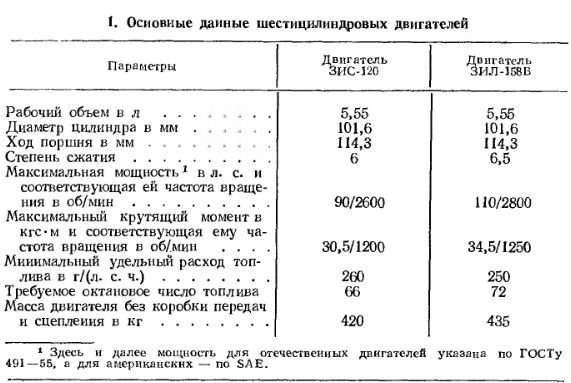
The introduction of a new engine model into production requires large investments both in manufacturing and in its operation and repair. Therefore, the decision to switch to the production of a new model can be made only after the full use of the resources of the engine model currently in production. Such a model at the automobile plant named after. I. A. Likhachev had a six-cylinder lower-valve engine ZIS-120 with a single-row arrangement of cylinders. At the beginning of production, this engine, intended for installation in a ZIS-150 vehicle with a lifting capacity of 4 tons, had the main parameters given in table. 1.
Improvements were made to the design of the ZIS-120 engine, which made it possible to produce modifications with higher parameters, for example the ZIL-158V engine. Comparison of data from table. 1 shows that engine power has increased by 22.5% and torque by 13%. This was achieved mainly by increasing the compression ratio, increasing the nominal crankshaft speed and using a more advanced carburetor, which made it possible to improve the filling of the engine cylinders.
Special work carried out to determine the possibility of boosting the ZIS-120 engine showed the following:
- Increasing the compression ratio leads to a slight increase in power and torque, but at the same time the required octane number of fuel increases significantly.
- Improving cylinder filling by expanding the flow sections of the intake tract is impossible, since it is impossible to increase the size of the valves due to their close location in the combustion chamber. The distance between the valve heads and the combustion chamber walls is small and is nominally 3.85 mm for both the intake and exhaust valves. Further increases in the diameter of the valve heads further reduce the flow area around them.
- Increasing the engine displacement is only possible by correspondingly changing the cylinder diameter, since a change in the piston stroke is prevented by the small gap between the camshaft cams and the lower connecting rod heads. However, it was not practically possible to increase the cylinder diameter, since with an increase in the working volume of the cylinders it is difficult to ensure their satisfactory filling. In addition, this reduces the width of the passage for water between the cylinders, which even with the existing diameter of the cylinders is only 4 mm.
For short-term experiments, an engine was nevertheless built with the cylinder diameter increased to 108 mm due to the installation of “wet” liners. The engine displacement increased by 13% and became 6.27 liters. With a compression ratio of 6 and a correspondingly expanded intake tract, this engine developed a power of 115 hp. With. (increase by 19%) and torque 35.5 kgf-m (increase by 15%).
- The use of overhead valves is equivalent to creating a new engine, which requires special equipment to produce new parts (including complex ones such as the cylinder head and block). However, this path has also been tested.
During testing, overhead valve engines with a compression ratio of 6.5 developed a maximum power of up to 130 hp. With. at n = 2800 rpm and maximum torque up to 39 kgf-m. Tests have also shown that these engines have increased wear of the main parts: cylinders, crankshaft journals, pistons, valve guides, etc. These engines, like lower valve engines, do not have reserves for further boost. Thus, the studies have shown that the six-cylinder in-line engine, both lower-valve and overhead-valve, does not meet the requirements for engines of modern trucks, and it is obvious that it is irrational to use such a cylinder arrangement for the family of new ZIL engines. Therefore, for the new engines, a V-shaped arrangement of cylinders with a camber angle between the rows of 90° was adopted. Compared to an in-line lower-valve engine, a V-shaped overhead valve engine has a number of advantages:
- Smaller length and height of the engine, which simplifies its installation on a modern truck.
- Smaller overall dimensions of the engine, and therefore less weight.
- Greater torsional rigidity of the crankshaft (due to a reduction in its length), virtually eliminating the need to install a torsional vibration damper.
- The shorter length of the intake channels and the identity of their shape ensure a high filling coefficient and greater uniformity of distribution of the working mixture among the cylinders.
- Possibility of increasing valve diameters. This is due to the fact that in a V-shaped engine the distance between its cylinders is greater than in a single-row engine (with the same displacement of one cylinder), and therefore it is possible to increase the length of the combustion chamber and, accordingly, the size of the valves.
For example, we can compare the V-shaped ZIL-375 engine with the single-row ZIL-164A engine, the working volumes of one cylinder differ by only 6%, and each of these engines, with the accepted distance between the cylinder axes, is made with the largest possible cylinder diameter ( Fig. 1).
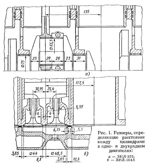
In a single-row engine, the distance between the axes of the cylinders is determined by the dimensions of the valves (which must be sufficient to satisfactorily fill the cylinders at the crankshaft speed corresponding to maximum power), the distances between the valves, between the valves and the walls of the combustion chamber, and the width of the bridge between adjacent combustion chambers. In a V-shaped engine, in addition to the above factors, one more is added: the need to place two connecting rods on one crankpin. In this regard, the distance between the axes of the cylinders in a V-shaped engine is determined by the sum of the longitudinal dimensions of the journals and cheeks of one crankshaft crank and in the ZIL-375 engine it is equal to 135 mm, which is 17.5 mm greater than this distance in the single-row ZIL-164A engine .
Accordingly, in the ZIL-375 engine the cylinder diameter is 6.4 mm larger and the combustion chamber is 12.5 mm longer than in the ZIL-164A engine, which makes it possible to increase the valve sizes, improve cylinder filling and increase engine power.
- An increase in the diameter of the cylinders and a corresponding decrease in the piston stroke make it possible to reduce its average speed, and therefore reduce friction losses, as well as wear of parts of the cylinder-piston group. All this increases the durability of the engine.
- The possibility of increasing the area of the displacers in the combustion chamber promotes turbulence of the charge, as a result of which combustion efficiency and engine power are increased and fuel with a lower octane number can be used.
- A decrease in the crank radius leads to an increase in the overlap of the main and connecting rod journals of the crankshaft (22.75 mm for the ZIL-375 engine and 6.85 mm for the ZIL-164A engine), resulting in increased rigidity of the crankshaft of a V-shaped engine.
- The relatively short length and high rigidity of the crankshaft in a V-shape make it possible to boost the engine's compression ratio.
- The possibility of increasing the flow sections of the intake and exhaust tracts allows for further boosting of the engine also in terms of rotation speed.
On this topic:
Technical specifications
Checking the tightness of the cylinder head bolts and nuts
ZIL 130
ENGINE
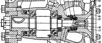
On a ZIS-150 car it is installed six-cylinder ZIS-120 engine with a power of 95 hp. With. with falling flow carburetorOperations 6 and 7 show longitudinal and transverse sections of the engine.
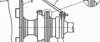
The engine is mounted on the frame at three points. The front engine support is a bracket mounted on the timing gear cover; the rear supports are the clutch housing feet. Massive rubber cushions are installed between the bracket and the front cross member of the frame, as well as between the clutch housing feet and the rear engine mounting brackets.
The elastic engine mount at three points on rubber cushions allows some misalignment of the frame relative to the engine without causing significant stress in the parts connecting the engine to the frame.
The cylinder block is cast iron. A developed system of reinforcing ribs and a lowered parting plane provide sufficient rigidity to the upper part of the engine crankcase.
Double walls along the entire length of the cylinders form an effective water jacket for the engine cooling system.
The thickness of the cylinder walls allows them to be bored after wear and pressed in liners.
The hatch on the left side of the cylinder block can be used when repairing the engine to remove scale.
In the plane of the junction of the cylinder block with the intake and exhaust pipelines, install a steel-fiber gasket with the smooth side facing the cylinder block.
The cylinder head is cast iron with untreated combustion chambers. A steel-asbestos gasket is also installed between the upper plane of the cylinder block and the head, which during installation should be installed with the smooth side facing the cylinder block.
The pistons are aluminum, with a cylindrical skirt and an oblique cut.
The gap between the cylinder and the piston is 0.08-0.1 mm. The gap is checked using a feeler tape pulled between the cylinder wall and the piston on the side opposite to the cut. If a piston without rings is inserted into the cylinder bottom down, a feeler tape 0.1 mm thick, 13 mm wide and at least 200 mm long should be pulled through with a force of 2.25-3.65 kg.
The pistons of one engine differ in weight by no more than 8 g.
There are four piston rings on each piston: three compression rings and one oil scraper ring (lower).
The rings are made using a special pattern processing method, which ensures the distribution of the radial pressure of the ring on the cylinder walls according to a given diagram.
The compression rings have: the top one - a chamfer on the inside, the second and third - a stepped groove on the outside. The top ring is installed on the piston with the chamfer up, the second and third rings with the groove down (operation 8). After installing the rings on the piston, their joints are separated, as shown in operation 9.
The gap in the ring lock when installing it in the cylinder should be in the range of 0.25-0.45 mm for compression rings (0.25-0.6 mm for chrome rings) and 0.15-0.30 <mm for oil - removable rings.
The upper compression ring is chrome plated.
Piston pins are floating type, hollow; They are kept from axial movements by spring retaining rings inserted into the grooves of the piston bosses. The finger works in the piston directly along the body of its bosses, in the upper head of the connecting rod - along two bronze bushings.
When assembling the piston - connecting rod - piston pin set, the piston is preheated (about 75 ° C), and the pin must fit freely into the holes of the bosses. The finger must fit tightly into the bushings of the upper head of the connecting rod without lubrication, under the force of the thumb. During final assembly of the piston and connecting rod, the pin must be lubricated with the oil used to lubricate the engine.
The connecting rods are steel, I-section. A channel is drilled along the entire length of the connecting rod, through which lubricant is supplied to the piston pin. Through a calibrated hole in the lower head of the connecting rod, lubricant is supplied to the cylinder walls.
When attaching the cover to the connecting rod, make sure that the boss marks on them face the same direction.
The connecting rod and connecting rod cap have numbers (on the base platforms) indicating the serial number of the cylinder into which the connecting rod is installed.
During assembly with the connecting rod, the piston is placed so that the arrow stamped on its bottom is facing the boss marks on the connecting rod. In this case, the oil spray hole in the lower head of the connecting rod will face in the direction opposite to the piston slot.
When installing piston-connecting rod assemblies into cylinders, the arrow on the piston crown should face the front of the engine.
It is necessary to ensure that the gap between the piston boss and the upper head of the connecting rod in the assembled engine is at least 1 mm.
Crankshaft - steel, forged, with counterweights; installed in the engine crankcase on seven main bearings. The shaft is dynamically balanced. To reduce the weight of the shaft and the load on the main bearings, the connecting rod journals are made hollow. To supply lubricant to the connecting rod journals, the latter are connected by lubrication channels to the main journals. To reduce wear, the crankshaft journals (main and connecting rods) are subjected to surface hardening with high-frequency currents.
A cast-iron flywheel with a steel ring gear is attached to the flange of the rear end of the crankshaft with six bolts to start the engine from the starter.
There is a mark stamped on the front end of the flywheel. When combined
If you mark the mark on the clutch housing (flywheel) hatch, the pistons of the 1st and 6th cylinders are at top dead centers.
When removing the flywheel, to facilitate subsequent assembly, it is necessary to mark its installation on the crankshaft, since the crankshaft flange has offset (asymmetrical) holes. The flywheel should be fastened to the crankshaft by uniformly tightening the nuts crosswise. After installing the flywheel, you should check the runout of its working surface (end) in relation to the axis of the crankshaft. At a radius of 150 mm, this runout should not be more than 0.1 mm,
The bearing caps are centered: connecting rod bearings - along the ground necks of the tie bolts, main bearings - along the sides in the grooves of the block.
Make sure that the boss marks on the main bearing caps face the front of the engine.
Each cover has a serial number, with the cover facing the corresponding number on the cylinder block, stamped on the camshaft side.
The liners are kept from turning by protrusions stamped on them, which fit into grooves milled in the block and main bearing caps, in the connecting rod and its cap.
Under the covers of the main and connecting rod bearings, gaskets with a thickness of 0.05 mm (one on each side) are installed at the joints.
When the crankshaft journals are worn, they are ground to the next size of repair liners.
The plant produces liners in four repair sizes, corresponding to a decrease in the diameter of the journals by 0.05; 0.3; 0.6 and 1.0 mm. Inserts of size - 0.05 are designed for installation on the shaft without regrinding the journals.
The camshaft is forged steel, mounted in the engine crankcase on four bearings equipped with steel bushings filled with Babbitt.
To reduce wear, the bearing journals, cams, eccentric and gear teeth are surface hardened with high frequency currents.
The camshaft cam profile is the same for both intake and exhaust valves. Valve lift height 10 mm.
The axial clearance of the shaft is limited and, if necessary, adjusted by a screw screwed into the timing gear cover. The required gap value A (operation 10) is set by screwing screw 1 all the way into the nut 3 and then turning it back by V12—Vs turns. After installation, the screw is secured with locknut 2.
To avoid damaging the cotter, the adjusting screw should not be tightened with great force.
The timing gears are made of: the driving gear is made of steel, the driven gear is made of cast iron.
The gas distribution is set when assembling the engine according to the marks stamped on the timing gears.
When installing the gas distribution, the marks should be located one against the other and lie on a straight line passing through the axes of the shafts, as shown in operation 11.
The valves - lower - are located on the right side of the cylinder block.
The intake valves are made of chrome steel, the diameter of the plate is 48.5 mm, the seat angle is 30°.
The exhaust valves are composite: the plate is made of heat-resistant silchrome steel, the rod welded to it is made of chrome steel. The diameter of the plate is 44 mm, the seat angle is 45°.
Valve pushers are disc type with adjustable clearance between valves and pushers.
The pushers are installed in two removable sections of guides, which, when the pushers wear out, allow them to be changed without disassembling the engine.
The front and rear sections of the guides are not interchangeable.
The gap between the pusher and the valve for the intake and exhaust valves is the same and is 0.20-0.25 mm.